EP0355588A2 - Dispositif de rotation graduelle pour un élément, notamment une vis d'un raccord en deux pièces pour l'assemblage de deux conduites immergées - Google Patents
Dispositif de rotation graduelle pour un élément, notamment une vis d'un raccord en deux pièces pour l'assemblage de deux conduites immergées Download PDFInfo
- Publication number
- EP0355588A2 EP0355588A2 EP89114741A EP89114741A EP0355588A2 EP 0355588 A2 EP0355588 A2 EP 0355588A2 EP 89114741 A EP89114741 A EP 89114741A EP 89114741 A EP89114741 A EP 89114741A EP 0355588 A2 EP0355588 A2 EP 0355588A2
- Authority
- EP
- European Patent Office
- Prior art keywords
- ring part
- ring
- rotation
- housing
- coupling unit
- Prior art date
- Legal status (The legal status is an assumption and is not a legal conclusion. Google has not performed a legal analysis and makes no representation as to the accuracy of the status listed.)
- Withdrawn
Links
Images


Classifications
-
- F—MECHANICAL ENGINEERING; LIGHTING; HEATING; WEAPONS; BLASTING
- F16—ENGINEERING ELEMENTS AND UNITS; GENERAL MEASURES FOR PRODUCING AND MAINTAINING EFFECTIVE FUNCTIONING OF MACHINES OR INSTALLATIONS; THERMAL INSULATION IN GENERAL
- F16L—PIPES; JOINTS OR FITTINGS FOR PIPES; SUPPORTS FOR PIPES, CABLES OR PROTECTIVE TUBING; MEANS FOR THERMAL INSULATION IN GENERAL
- F16L19/00—Joints in which sealing surfaces are pressed together by means of a member, e.g. a swivel nut, screwed on, or into, one of the joint parts
-
- B—PERFORMING OPERATIONS; TRANSPORTING
- B25—HAND TOOLS; PORTABLE POWER-DRIVEN TOOLS; MANIPULATORS
- B25B—TOOLS OR BENCH DEVICES NOT OTHERWISE PROVIDED FOR, FOR FASTENING, CONNECTING, DISENGAGING, OR HOLDING
- B25B21/00—Portable power-driven screw or nut setting or loosening tools; Attachments for drilling apparatus serving the same purpose
- B25B21/002—Portable power-driven screw or nut setting or loosening tools; Attachments for drilling apparatus serving the same purpose for special purposes
-
- E—FIXED CONSTRUCTIONS
- E21—EARTH OR ROCK DRILLING; MINING
- E21B—EARTH OR ROCK DRILLING; OBTAINING OIL, GAS, WATER, SOLUBLE OR MELTABLE MATERIALS OR A SLURRY OF MINERALS FROM WELLS
- E21B19/00—Handling rods, casings, tubes or the like outside the borehole, e.g. in the derrick; Apparatus for feeding the rods or cables
- E21B19/16—Connecting or disconnecting pipe couplings or joints
-
- F—MECHANICAL ENGINEERING; LIGHTING; HEATING; WEAPONS; BLASTING
- F16—ENGINEERING ELEMENTS AND UNITS; GENERAL MEASURES FOR PRODUCING AND MAINTAINING EFFECTIVE FUNCTIONING OF MACHINES OR INSTALLATIONS; THERMAL INSULATION IN GENERAL
- F16L—PIPES; JOINTS OR FITTINGS FOR PIPES; SUPPORTS FOR PIPES, CABLES OR PROTECTIVE TUBING; MEANS FOR THERMAL INSULATION IN GENERAL
- F16L1/00—Laying or reclaiming pipes; Repairing or joining pipes on or under water
- F16L1/26—Repairing or joining pipes on or under water
Definitions
- the invention relates to a device for the gradual turning of at least one object, in particular a screw of a two-part connecting element for joining two pipes under water, in which for each object on a frame a gripping device for a rotationally fixed connection to the object and a coupling unit accommodated in the frame are arranged, which is connected to the gripping device and carries it, wherein a drive device for rotating the gripping device is connected to the coupling unit.
- the first installation part can be located on the sea floor, while a second installation part - connecting element and rotating device - can be attached to a remote-controlled underwater vehicle floating on the water surface, the gripping devices of the connecting element, which can be sleeve-shaped, connected in a rotationally fixed manner to the connecting element are.
- the vehicle with this load is then lowered into the submerged position and led down to the first installation part - for example to two pipe flanges to be connected - the said flanges being brought together, in such a way that the connecting element surrounds the flanges.
- the flanges are then connected by tightening the screws of the connector using the rotating device, after which the connector and rotating device are detached from the vehicle and left on the sea floor.
- the vehicle is then brought back to the water surface.
- the vehicle When the first and second installation parts are to be separated, the vehicle is led down to the installation parts and is maneuvered so that the end piece of each screw is inserted into a sleeve and the rotating device is attached to the vehicle with its frame.
- the rotating device is then operated in such a way that the connecting element is released, after which the vehicle is brought to the surface again with the rotating device and the connecting element.
- the remote-controlled vehicle then carries the second installation part - the rotating device and the connecting element - with both parts being attached to the side of the vehicle.
- the vehicle is loaded both by the weight of the load and by the static moment of force exerted by the load on the vehicle.
- the components used in this technology can be very heavy and also very bulky and it is therefore of great importance that a rotating device of the type mentioned is as small and light as possible so that the capacity of the vehicle in terms of carrying capacity and stability is not is exceeded.
- Rotary devices are already known in which the coupling housing is immovably mounted in relation to the frame and the gripping devices consist of relatively long, sleeve-shaped universal joints which are intended to ensure that the end pieces of the screws of the gripping device despite possible deviations from the nominal dimensions with regard to the distance between the longitudinal axes of the screws and their parallelism can be recorded.
- the clutches represent locking devices, and because the torque to be generated by the clutches can be large, they are divided into a series of locking elements which have to be in engagement with a row of teeth at the same time. To loosen the connecting element, the screws in the ver Ratio to the direction of rotation while tightening in the opposite direction. It must therefore be possible to change the direction of rotation of the rotating device.
- a turning device is very complicated and comprises many interacting individual parts that have to be manufactured with low tolerance and therefore also become very expensive.
- such a rotating device is heavy, and due to the long universal joints, the center of gravity of the connecting element and the second installation part is at a fairly large distance from the vehicle, so that the tilting moment exerted by the load against the vehicle also becomes large.
- the invention has for its object to provide a turning device which avoids the above-mentioned shortcomings.
- the coupling unit has a housing which is movably mounted in the frame. In this way, the gripping device can be moved close to the coupling unit, so that a compact unit is created.
- the housing can advantageously be tilted about axes which are at least approximately in a plane which runs centrally through the coupling unit, parallel to the plane of rotation of the gripping device, the housing being displaceable in a plane which comprises the axis of rotation.
- the device according to the invention can be designed in such a way that the coupling unit has a first ring part and a second ring part, and the ring parts are arranged concentrically to the axis of rotation of the gripping device and are rotatably mounted in the housing so that they can rotate about this axis so that the two ring parts axially directed teeth have that the ring parts are axially displaceable against each other between a first position in which the teeth of the ring parts are engaged with each other and a second position in which the teeth are not in engagement with each other. This keeps the volume and weight of the rotating device small.
- a favorable embodiment of the device according to the invention is achieved in that the first ring part is firmly connected to the gripping device and the second ring part with the drive device, that the second ring part and the housing have cooperating stops for limiting the rotational movement of this ring part relative to the housing with each turning operation , and that the drive device is designed such that alternating torques acting in the opposite direction are exerted against the second ring part, the ring part being able to be in a predetermined first position if the torque is exerted against the second ring part during a first turning operation and in a second position if the torque acts in the opposite direction during a second turning operation or vice versa.
- the second ring part has at least one eyelet which is directed radially outwards approximately in the central plane of rotation
- the drive device comprises a corresponding number of double-acting hydraulic cylinders, the cylinder part articulated with the eyelet and the piston part articulated with the frame or are connected in reverse.
- the second ring part of the two coupling units belonging to each of the screws can have two diametrically opposed eyelets which are directed radially outwards approximately in the central plane of rotation and on each side of a connecting line between the axes of rotation of the couplings, the cylinder part and the piston part of the two hydraulic cylinders are connected in an articulated manner to the respective eyelets of the second ring parts lying on the same side of the connecting line.
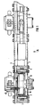
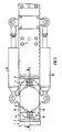
- a device according to the invention is shown which is designed for turning two right-hand and left-hand thread screws of a two-part connecting element.
- the device according to the invention is in a position in which the axes of rotation for the gripping devices lie in the same horizontal plane.
- the right or left side of the device is to be understood as the right or left side of this device, as can be seen from FIGS. 1 and 2.
- the longitudinal direction of the device is to be understood as the direction of the axes of rotation of the gripping devices.
- the device comprises a frame 1 with a front plate 2 and a rear plate 3. Between the two plates 2, 3 by means of screws 4 are a right and a left pair of U-shaped bearing blocks in horizontal section 5 attached. The bearing blocks 5 with legs 6 turned against one another are arranged within the pairs.
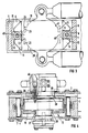
- a cylindrical pin 7 extends through the opening in the legs 6 of each bearing block 5 in the longitudinal direction of the device and carries a self-aligning ball bearing 8 (FIGS. 3, 4) in the section between the legs 6.
- the outer ring 11 of the bearing 8 has horizontal contact surfaces 9, 10 at the top and bottom.
- a coupling unit 12 which comprises a housing 13 with fork-shaped bearing eyes 14 which protrude between the legs 6 of the bearing blocks 5, the Bearing eyelets 14 have flat contact surfaces 15, 16 which are provided to slide on the contact surfaces 9 and 10 of the self-aligning ball bearing 8.
- the dimension of the bearing eyelets 14 in the longitudinal direction of the device is somewhat less than the distance between the legs 6 of the bearing blocks 5.
- the distance between the bottom surfaces, which lie between the prongs of the fork-shaped bearing eyes of each housing 13 is in turn slightly smaller than the distance between the surfaces of the bearings facing each other, outer rings 11 of the bearings in the pairs of bearing blocks 5.
- the housing 13 has a substantially cylindrical bore 17 which is open to the front and a rear end wall 18.
- An upper continuous recess 19 and a lower continuous recess 20 extend from the cylindrical bore. (FIG. 3)
- a right-hand recess 21 (pocket) and a left-hand recess 22, (pocket) each extend from the bore 17, each with a cylindrical bottom portion 23 which runs coaxially with respect to the bore 17 and which is supported by an upper, radially extending shoulder 24 (contact surface). and a lower radially extending shoulder 25 (contact surface) is completed.
- a front end wall (end wall) 26 is attached to the front part of the housing 13 with the aid of screws (FIG. 4).
- a rear slide bearing 29 and a front slide bearing 30 are arranged in the end walls 18 and 26, in which a first ring part 31 is rotatably and displaceably mounted in the housing 13 is.
- This has a section 35 directed radially outwards against the inner wall of the housing 13 with a row of radially extending teeth 33 turned towards the rear.
- a second ring part 32 is arranged radially outside of the first ring part 31, namely with a row of radially extending teeth 34 turned forward, provided for the simultaneous engagement in the teeth 33 of the first ring part 31. Furthermore, the second ring part 32 has two pairs of eyelets 36, 37 (FIG. 6) which protrude upwards and downwards through the cutouts 19 and 20 (FIG. 4) of the housing 13 and two stops 48, 49, which are directed radially to the right or left, namely into the respective recesses (pockets) 21 and 22 of the housing 13, where they come to bear against the end faces (shoulders) 24, 25.
- a third ring part 38 surrounds the radially projecting section 35 of the first ring part 31 and is connected to the second ring part 32 by screws 39 (FIG. 6).
- the first ring part 31 has cylindrical sliding surfaces on the outside, which interact with inner sliding surfaces of the second and third ring parts.
- sealing rings 40 which bear against the adjacent sliding surfaces, are fitted in such a way that the first ring part 31 forms a seal and can rotate and move axially in relation to the second and third ring parts 32, 38, namely between a first position, in which the teeth 33, 34 of the ring parts 31, 32 engage one another and a second position in which the teeth do not engage one another.
- a series of compression springs 41 (FIG. 5) are attached between the first and the second ring part and strive to axially push these ring parts apart.
- the second ring part 32 and the third ring part 38 there are bores which form a channel 50 after the ring parts have been screwed, an end section of the channel 50 being intended to establish a connection with a hydraulic unit which supplies the pressure oil via, for example, a circular opening 55 in the rear wall 18 provides, and wherein the other end portion opens out on superimposed, radially extending surfaces 53 and 54 of the first and third ring parts 31 and 38.
- the pressure oil flowing into the channel 50 and between these surfaces then tends to push the first ring member 31 down and the second and third ring members upward, thereby engaging the teeth 33, 34 of the ring members with one another while the springs 41 strive to disengage them.
- a further channel 56 can also be provided in the second ring part 32, wherein one end section of the channel 56 can be designed for connection to an aggregate that supplies pressure oil via an, for example, circular opening 57 in the housing, the other end of the channel 56 in can open out the space between the teeth of the ring parts, in such a way that the first and second ring parts are pressed apart when pressure oil flows into the channel 56.
- the sealing rings 40 ensure the sealing of the chambers to which pressure oil is supplied.
- a first disk 42 is attached to the rear end portion of the first ring part 31, and a second disk 43 is attached to the rear end wall 18 of the housing 13 in a rotationally fixed but axially displaceable manner in relation thereto.
- Two disc springs 44 are arranged between the disks, in such a way that there is a frictional effect when the first ring part 31 and the housing 13 are rotated in opposite directions.
- a gripping sleeve 46 with a radially displaceable and radially inwardly sprung wedge 47 is fastened to the front end section of the first ring part 31 with the aid of screws 45 (FIG. 4).
- the bore diameter of the gripper sleeve 46 is based on the diameter of the end piece of screws, not shown, of connecting elements, e.g. Pipe connectors matched, and the wedge 47 is intended to be inserted, for example, in an axially extending groove of the screws mentioned, so that a rotationally fixed connection between the gripping sleeve and the associated screws is made. Furthermore, the outer end portion of the bore of the gripper sleeve 46 is drawn.
- Two double-acting hydraulic cylinders 51, 52 are connected via the self-aligning ball bearings 8 to the upper eyelets 36 (FIG. 6) and the lower eyelets 37 of the second ring part 32, the The cylinder part of the hydraulic cylinders 51, 52 is connected to the eyes of the left clutch unit 12 (FIG. 2) and the piston part is connected to the eyes of the right clutch unit 12.
- the hydraulic cylinders 51, 52 are connected to a hydraulic unit, not shown, which in and of itself as can be assumed to be known and to which a control unit, not shown here, can be connected for sequential control of the oil supply to the channels 50 (FIG. 5) and the hydraulic cylinders 51, 52.
- the device is displaced so that the ends of the screws are moved against the respective gripping sleeves to be inserted therein, the chamfer 46a of the sleeve bore ( Figure 7) facilitating insertion. If the distances between the longitudinal axes of the screws (or their parallelism) deviate from the nominal dimensions, the arrangement of the self-aligning ball bearings 8 for the housing 13 allows the coupling units to be tilted individually about a horizontal central axis.
- the cooperating outer rings 11 and the bearing eyelets 14 also allow the coupling units to be tilted (angled) individually about a vertical central axis through the respective coupling unit, and the play between the bearing eyelets 14 and the self-aligning ball bearings 8 enables the coupling units to be moved individually in the transverse direction, in this way that the screws can be easily inserted completely into the gripping sleeves 46.
- the device according to the invention can also be used with individual design for systems with only one screw, for example if one Part of the hydraulic cylinder is connected directly to the frame via a joint instead of to one of the coupling units.
- the screws When turning two screws, it is advantageous if the screws have opposite threads in relation to each other.
- the device can also be designed so that two screws with the same thread are turned, for example, the piston part of the upper hydraulic cylinder is connected by a hinge to the lower fork-shaped eyes 36 of the second ring part of the right coupling unit and the piston part of the lower hydraulic cylinder articulated with the upper fork-shaped eyelets 36 of this ring part is connected, via additional intermediate arms, which are firmly connected to the piston rods.
Landscapes
- Engineering & Computer Science (AREA)
- General Engineering & Computer Science (AREA)
- Mechanical Engineering (AREA)
- Geology (AREA)
- Life Sciences & Earth Sciences (AREA)
- Mining & Mineral Resources (AREA)
- Environmental & Geological Engineering (AREA)
- Fluid Mechanics (AREA)
- General Life Sciences & Earth Sciences (AREA)
- Geochemistry & Mineralogy (AREA)
- Physics & Mathematics (AREA)
- Transmission Devices (AREA)
- Earth Drilling (AREA)
- Power-Operated Mechanisms For Wings (AREA)
Applications Claiming Priority (2)
| Application Number | Priority Date | Filing Date | Title |
|---|---|---|---|
| NO883771A NO164824C (no) | 1988-08-23 | 1988-08-23 | Innretning til trinnvis dreining av en gjenstand. |
| NO883771 | 1988-08-23 |
Publications (2)
| Publication Number | Publication Date |
|---|---|
| EP0355588A2 true EP0355588A2 (fr) | 1990-02-28 |
| EP0355588A3 EP0355588A3 (fr) | 1991-01-30 |
Family
ID=19891184
Family Applications (1)
| Application Number | Title | Priority Date | Filing Date |
|---|---|---|---|
| EP19890114741 Withdrawn EP0355588A3 (fr) | 1988-08-23 | 1989-08-09 | Dispositif de rotation graduelle pour un élément, notamment une vis d'un raccord en deux pièces pour l'assemblage de deux conduites immergées |
Country Status (2)
| Country | Link |
|---|---|
| EP (1) | EP0355588A3 (fr) |
| NO (1) | NO164824C (fr) |
Cited By (1)
| Publication number | Priority date | Publication date | Assignee | Title |
|---|---|---|---|---|
| NL1005891C2 (nl) * | 1997-04-24 | 1998-10-27 | Allseas Group Sa | Werkwijze en inrichting voor het onder water verbinden van leidingstukken en bout daarvoor. |
Families Citing this family (1)
| Publication number | Priority date | Publication date | Assignee | Title |
|---|---|---|---|---|
| CN114274170A (zh) * | 2021-12-17 | 2022-04-05 | 镇江市高等专科学校 | 一种机械手旋转装置 |
Family Cites Families (2)
| Publication number | Priority date | Publication date | Assignee | Title |
|---|---|---|---|---|
| US3739663A (en) * | 1971-04-16 | 1973-06-19 | Byron Jackson Inc | Chain actuated pipe tongs |
| US4027561A (en) * | 1975-11-19 | 1977-06-07 | Junkers John K | Hydraulic wrench |
-
1988
- 1988-08-23 NO NO883771A patent/NO164824C/no unknown
-
1989
- 1989-08-09 EP EP19890114741 patent/EP0355588A3/fr not_active Withdrawn
Cited By (1)
| Publication number | Priority date | Publication date | Assignee | Title |
|---|---|---|---|---|
| NL1005891C2 (nl) * | 1997-04-24 | 1998-10-27 | Allseas Group Sa | Werkwijze en inrichting voor het onder water verbinden van leidingstukken en bout daarvoor. |
Also Published As
| Publication number | Publication date |
|---|---|
| NO164824B (no) | 1990-08-13 |
| EP0355588A3 (fr) | 1991-01-30 |
| NO164824C (no) | 1990-11-21 |
| NO883771D0 (no) | 1988-08-23 |
| NO883771L (no) | 1990-02-26 |
Similar Documents
| Publication | Publication Date | Title |
|---|---|---|
| DE69115391T2 (de) | Vorrichtung zur Aufwendung eines Drehmomentes auf ein rohrförmiges Element | |
| EP0507147B1 (fr) | Accouplement | |
| DE69427925T2 (de) | Notauslösbare kupplung mit leckagefrei trennbaren doppelkugelventilen | |
| EP1239087A1 (fr) | Accouplement rapide | |
| DE4003201C2 (de) | Schnellkupplungsvorrichtung für Schmiede- und Transportmanipulatoren | |
| DE19525574C1 (de) | Spannvorrichtung zum genauen gegenseitigen Fixieren zweier Bauteile | |
| DE102005031142A1 (de) | Spannvorrichtung, Grundbacken und Aufsatzbacken dafür | |
| EP1455969A1 (fr) | Dispositif de compression | |
| EP0350516B1 (fr) | Dispositif de changement rapide de mandrins | |
| DE1502035A1 (de) | Spannfutter mit Schwenkarmen | |
| EP0012101B1 (fr) | Dispositif de mise en rotation des écrous cylindriques de plusieurs boulons filetés disposés en cercle pour la fermeture d'une enceinte à pression, notamment d'une cuve de réacteur | |
| DE3731281A1 (de) | Vorrichtung zur steuerung der linearen bewegung eines koerpers | |
| DE69105692T2 (de) | Angetriebener schraubenschlüssel. | |
| DE19636594A1 (de) | Löseeinheit | |
| DE3300227C2 (de) | Vorrichtung zur lösbaren Verbindung von Greiferschienenteilen der Greiferschienen in einer Transfer-Presse | |
| DE102021121113B3 (de) | Kopplungseinrichtung für einen Roboter, Kopplungsteileinrichtung hierfür sowie Roboter mit einer Kopplungseinrichtung | |
| DE10140308A1 (de) | Magnetgesteuerte Gestängeverbindung | |
| DE4110720C2 (fr) | ||
| EP0355588A2 (fr) | Dispositif de rotation graduelle pour un élément, notamment une vis d'un raccord en deux pièces pour l'assemblage de deux conduites immergées | |
| DE19813854A1 (de) | Vorrichtung zur Herstellung von Quetschverbindungen | |
| EP0458289B1 (fr) | Connexion pour tubes de forage ou analogues | |
| DE3614511A1 (de) | Spannfutter | |
| DE2953734A1 (en) | Device for tightening large-sized threaded joints | |
| DE3518581A1 (de) | Werkzeugwechseleinrichtung | |
| EP1896219B1 (fr) | Point de raccordement |
Legal Events
| Date | Code | Title | Description |
|---|---|---|---|
| PUAI | Public reference made under article 153(3) epc to a published international application that has entered the european phase |
Free format text: ORIGINAL CODE: 0009012 |
|
| AK | Designated contracting states |
Kind code of ref document: A2 Designated state(s): DE GB |
|
| PUAL | Search report despatched |
Free format text: ORIGINAL CODE: 0009013 |
|
| AK | Designated contracting states |
Kind code of ref document: A3 Designated state(s): DE GB |
|
| STAA | Information on the status of an ep patent application or granted ep patent |
Free format text: STATUS: THE APPLICATION IS DEEMED TO BE WITHDRAWN |
|
| 18D | Application deemed to be withdrawn |
Effective date: 19910731 |