EP0355877A1 - Optisches Netzwerk - Google Patents
Optisches Netzwerk Download PDFInfo
- Publication number
- EP0355877A1 EP0355877A1 EP89201604A EP89201604A EP0355877A1 EP 0355877 A1 EP0355877 A1 EP 0355877A1 EP 89201604 A EP89201604 A EP 89201604A EP 89201604 A EP89201604 A EP 89201604A EP 0355877 A1 EP0355877 A1 EP 0355877A1
- Authority
- EP
- European Patent Office
- Prior art keywords
- network
- transmission
- signals
- optical
- control
- Prior art date
- Legal status (The legal status is an assumption and is not a legal conclusion. Google has not performed a legal analysis and makes no representation as to the accuracy of the status listed.)
- Granted
Links
- 230000003287 optical effect Effects 0.000 title claims abstract description 46
- 230000005540 biological transmission Effects 0.000 claims abstract description 86
- 239000004020 conductor Substances 0.000 claims abstract description 19
- 238000000926 separation method Methods 0.000 claims abstract description 4
- 230000008878 coupling Effects 0.000 claims description 8
- 238000010168 coupling process Methods 0.000 claims description 8
- 238000005859 coupling reaction Methods 0.000 claims description 8
- 239000003365 glass fiber Substances 0.000 abstract description 67
- 230000010287 polarization Effects 0.000 abstract description 2
- 238000006243 chemical reaction Methods 0.000 description 6
- 230000009977 dual effect Effects 0.000 description 2
- 230000000694 effects Effects 0.000 description 2
- 230000002441 reversible effect Effects 0.000 description 2
- 230000001427 coherent effect Effects 0.000 description 1
- 238000012423 maintenance Methods 0.000 description 1
- 238000009666 routine test Methods 0.000 description 1
Images


Classifications
-
- H—ELECTRICITY
- H04—ELECTRIC COMMUNICATION TECHNIQUE
- H04L—TRANSMISSION OF DIGITAL INFORMATION, e.g. TELEGRAPHIC COMMUNICATION
- H04L12/00—Data switching networks
- H04L12/28—Data switching networks characterised by path configuration, e.g. LAN [Local Area Networks] or WAN [Wide Area Networks]
- H04L12/42—Loop networks
-
- H—ELECTRICITY
- H04—ELECTRIC COMMUNICATION TECHNIQUE
- H04B—TRANSMISSION
- H04B10/00—Transmission systems employing electromagnetic waves other than radio-waves, e.g. infrared, visible or ultraviolet light, or employing corpuscular radiation, e.g. quantum communication
- H04B10/25—Arrangements specific to fibre transmission
- H04B10/2589—Bidirectional transmission
Definitions
- the invention relates to a network for transmitting information signals between stations connected to that network, which is provided with a number of switching devices and a number of transmission sections, which switching devices can switch on, switch over or switch off parts of the network or stations connected to the network by means of control signals, and which transmission sections achieve the transmission of information signals between one switching device and another respectively between the switching devices and the stations connected to the network, for which purpose the information signals are supplied to those transmission sections on one side of them, and are separated on the other side of them, and which transmission sections comprise one or more parallel optical conductors (e.g.
- a network as mentioned above is known from "TELEPHONY′ of April 15, 1985 [1], notably pp. 60-64, in which various network configurations are described, substantially formed by transmission sections and switching devices.
- External stations hosts
- the transmission section which has come from a suchlike station is connected to a switching device, which is connected to the rest of the network, in this case to other switching devices, via further transmission sections.
- the switching device has the function either to connect the latter transmission sections to one another and to close in itself at the same time the transmission section coming from the host (first switching state), or to insert this transmission section coming from the host between the transmission sections connected to the rest of the network (second switching state).
- the control of the switching device takes place from the host: after the host has controlled its transmission section for a correct working - the switching device is in said first switching state - it will transmit a control signal ("JOIN" command) to the switching device. Owing to this control signal the switching device switches over to said second switching state, as a result of which the host will be inserted into the network. When the host wants to discontinue its connection to the network, it will transmit for that purpose a control signal to the switching device again, as a result of which this switching device will come into the former state again.
- JOIN control signal
- the network can also comprise switching devices for effecting a reconfiguration of the network, for example in the event of a disturbance or for the sake of maintenance. These switching devices are then controlled - by means of control signals - for example by one another or by a central device.
- the transmission sections the transmission of the signals takes place substantially in the optical domain: the transmission sections consist of one or more glass fibres, which are connected at both ends to E/O converters, where electric signals are converted into optical signals or vice versa.
- the switching of the transmission sections takes place in the electrical domain, in other words, the switching devices are electric as to their nature.
- control signals are transmitted next to the information signals via the same glass fibres.
- intelligence is added to the E/O-converters and the control signals and the information signals in the electrical domain are joined by means of multiplexing or separated from one another by means of demultiplexing.
- the known network can transmit only those information signals and control signals for which the conversion devices are suited. Consequently it will be possible to realize future changes with regard to the sort and/or the speed of transmission to a limited degree without adapting or replacing all (!) the conversion devices in the network - if that would be possible -.
- the object of the present invention is to provide a network of the sort indicated under par. A. 1., the drawbacks of the known network mentioned in the last part of par. A. 2. being overcome.
- the present invention provides a network of the aforesaid type in which the transmission of said signals in the transmission sections, as well as the switching in the switching devices, and the supply of the control signals and the information signals to the relevant transmission sections and the separation of these signals from said transmission sections fully take place in the optical domain. So the information signals need not be converted at several points from the optical domain to the electrical domain and vice versa - as in the known network configuration -.
- control signals and the information signals in said relevant transmission sections are - according to a further embodiment of the invention - distinguishable from each other in the optical domain, and the relevant control signals and information signals are directly coupled in into one and the same optical conductor respectively coupled out of the same.
- control signal and the information signal distinguish themselves in the optical domain by means of different transmission modes: for example the respective wavelengths or the respective polarization modes of the control signal and of the information signal can be different.
- this distinction can moreover and preferably be effected by transmitting the control signals and the information signals which make use of the same optical conductor via this optical conductor in a direction which is different (opposite) for each signal.
- a control signal is then transmitted to the switching device via a glass fibre, which is at the same time meant for the transmission of information signals in the opposite direction, so from that very switching device.
- control signals are in the relevant transmission sections coupled in on a first side of the relevant optical conductor into that conductor, and are coupled out of that conductor on an opposite, second side of it, whereas the information signals, on the other hand, are coupled in on the second side of that optical conductor into that conductor, and are coupled out of that conductor on the first side of it.
- Said coupling devices are preferably formed by fused couplers known per se (vide ref. [2]). These couplers have small dimensions, they are comparatively cheap and have moreover the advantage that they can be made in such a way that they will have the desired selectivity with regard to the respective wavelength and/or direction of the control signals and the information signals.
- the network shown in figure 1 comprises a number of simple optical transmission sections 1 connected to a number of optical switching devices 2 via connections 15 and 16.
- Double transmission sections 3 forming the connection between the switching devices 2 and external stations 4 (one of which is shown in the figure) are also connected to the switching devices 2.
- Said stations 4 have an optical information signal output terminal 5 and an optical information signal input terminal 6, as well as an optical control signal output terminal 7; the output terminals 5 and 7 are connected in the station to an optical transmitter, the input terminal 6 is connected to an optical receiver.
- the transmission section 3 comprises a glass fibre 8 for the transmission of information signals from the station 4 to the network, in this case the switching device 2, and a glass fibre 9 for the transmission of information signals from the network - in this case the switching device 2 - to the station 4.
- the latter glass fibre 9 moreover serves for the transmission of control signals from the station to the switching device 2.
- the optical output terminal 7 is also connected to said glass fibre 9, namely by means of an optical coupler (e.g. a fused coupler; vide ref. [2]).
- the glass fibre 9 serves for the transmission of information signals from the switching device 2 to the station 4 as well as for the transmission of control signals from the station 4 to the switching device 2, in which case, however, the direction of transmission of the control signals (indicated by arrows "c") is opposite to the direction of transmission of the information signals (everywhere in the figure indicated by arrows "d").
- FIG. 2 shows a further detailed view of the network part with the station connected to it as already represented in its entirety in figure 1.
- the switching device 2 i.e. an optical switch (e.g. a fused coupler switch; vide ref. [3]) belonging to that switching device 2, is controlled by means of a control device 17 also belonging to that switching device 2.
- the switching device Under the control of the control signal c supplied to this control device 17 the switching device can have two different switching states: - in the first switching state the switching device 2 effects two optical connections at the same time, to wit one between the terminals 12 and 13 and one between the terminals 15 and 16; - in the second switching state the switching device 2 effects two other optical connections at the same time, to wit one between the terminals 12 and 16 and one between the terminals 13 and 15.
- the control of the switching device 2 takes place by the control signal c, which is supplied to that switching device 2 via the terminal 14.
- the switching device 2 has the former switching state prior to an actual connection between the station 4 and the network; so the former switching state is the DEFAULT-state. In this state, in which consequently on the one hand the network ring is closed via the terminals 15 and 16 and on the other hand the glass fibres 8 and 9 connected to the station 4 are through-connected with each other via the terminals 12 and 13, the station 4 can test its own working and that of the connecting section 3 before being allowed to enter the network.
- the station 4 can deliver a "JOIN RING" signal, as a result of which the switching device 2 will come into its latter switching state and consequently will insert the glass fibres 8 and 9 and the station 4 into the network by means of discontinuing the connections between the terminals 12 and 13 respectively 15 and 16, and by through-connecting the terminals 12 and 16 respectively 13 and 15.
- the (physical) discontinuance of the connection between the station and the network can take place in the same way - by supplying a control signal to the switching device - as in which the connection to the network was effected.
- control signals c from the station 4 to the switching device 2 are transmitted via the same glass fibre 9 as the information signals d, which are transmitted from the network - via the switching device 2 - to the station 4. So the control signals and the information signals have in this embodiment opposite directions of transmission, which has the advantage that for joining as well as for separating the control signal and the information signal simple couplers (e.g. fused couplers) can be used.
- the control signal is preferably transmitted at a wavelength of 850 nm and the information signal at a wavelength of 1300 nm.
- a switching device can also be controlled by some other switching device of the network.
- the network at least the ring-shaped part of it, is designed in duplicate, in order to ensure that in the event of a disturbance or during work on part of the network ring, the information signals can be diverted, due to which the network - or at least a large part of it - can remain operating.
- Such network configurations are known per se inter alia from the publication mentioned under B.
- Figure 3 shows such a network configuration, which corresponds to the "Dual Reversible Fiber Ring" known from said publication.
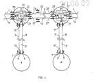
- Figure 4 shows a further detailed representation of (part of) figure 3, to wit a pair of stations 4 respectively 4′, connected to the switching devices 2 respectively 2′ via the transmission sections 3 respectively 3′.
- the switching devices 2 and 2′ are connected to each other by means of a double transmission section 30, formed by the glass fibres 1 and 1a, and each of them comprises three optical switches 21, 22, 23 respectively 21′, 22′, 23′ (e.g. fused coupler switches; vide ref. [3]), which are controllable from a control device 24 respectively 24′.
- the station 4 wants to be switched into the network, it will give the control signal "JOIN RING" via the glass fibre 9.
- This control signal is supplied to an optical receiver in the control device 24, under the influence of which this control device 24 delivers a switch signal s to the switch 21, which switches over to a state in which the glass fibre 8, the station 2 and the glass fibre 9 will be inserted into the network, id est between two successive glass fibres 1.
- this control device 24 delivers a switch signal s to the switch 21, which switches over to a state in which the glass fibre 8, the station 2 and the glass fibre 9 will be inserted into the network, id est between two successive glass fibres 1.
- the station 2′ is inserted into the network, and the stations 2 and 2′ can exchange information signals via the glass fibres 1 (see also figure 3).
- information signals from station 2 to station 2′ successively pass through the glass fibre 8, the switch 21, the switch 23, the consecutive glass fibres 1 (clockwise), the switch 22′, the switch 21′ and the glass fibre 9′.
- Information signals from station 2′ to station 2 successively pass through the glass fibre 8′, the switch 21′, the switch 23′, the glass fibre 1, the switch 22, the switch 21 and the glass fibre 9.
- the glass fibre 1a between the switching devices 2 and 2′ is used for the transmission of information signals only in the event of a disturbance and the like, in which case the direction of the transmitted information signals is opposite to the direction of the information signals through the glass fibres 1, which is described in detail in ref. [1].
- This datum is made use of in the present embodiment for transmitting control signals between the switching devices 2 and 2′. These signals are here, just like in the connection between the switching devices 2 respectively 2′ and their connected stations 4, transmitted in a direction which is opposite to the direction in which the information signals are transmitted.
- control signals from the switching device 2 to the switching device 2′ can be transmitted via the glass fibre 1 (which primary serves for the transmission of information signals from the switching device 2′ to the switching device 2); control signals from the switching device 2′ to the switching device 2 can be transmitted via the glass fibre 1a (which primary serves as a spare glass fibre for the transmission of information signals from the switching device 2 to the switching device 2′).
- the control signals from the switching device 2 to the switching device 2′ are coupled in into the glass fibre 1 by means of a coupling device 26 and the information signals from the switching device 2′ to the switching device 2 by means of a coupler 26′.
- control signals from the switching device 2′ to the switching device 2 are coupled in into the glass fibre 1a by means of a coupling device 27′ and - in case the spare glass fibre 1a is in use - the information signals from the switching device 2 to the switching device 2′ by means of a coupler 27.
- the control signals from the switching device 2 to the switching device 2′ are coupled out of the glass fibre 1 by means of the coupling device 26′ and the information signals from the switching device 2′ to the switching device 2 by means of the coupler 26.
- control signals from the switching device 2′ to the switching device 2 are coupled out of the glass fibre 1a by means of a coupling device 27 and - in case the spare glass fibre 1a is in use - the information signals from the switching device 2 to the switching device 2′ by means of a coupler 27′.
- control signal has in fact two functions, to wit that of a pilot signal and that of an actual control signal: by continuously watching over the existence of the control signal in a certain glass fibre it can be detected whether that glass fibre functions or does not function, and by means of the (command) contents of the control signal to a certain (addressed) control device within the network a reconfiguration of the network can be effected.
- some possible disturbances will be dealt with and also the way in which the network according to the present embodiment of the invention works. It will then also appear that for watching the whole network it will not be necessary to watch all the glass fibres by means of a control/pilot signal.
- the switching device 2 it is detected by the control device 24 that the control/pilot signal is missing, after which the switch 21 is switched over by the control device 24, as a result of which the station 4 will be switched off from the network and the glass fibres 1 on both sides of the switching device 2 will be through-connected to each other via the switches 22 and 23.
- This glass fibre 9 is directly watched by the control/pilot signal, so that in the event of a break in it the control device 24 will detect the missing of the control/pilot signal and will switch over the switch 21.
- This glass fibre 8 is not watched by a control/pilot signal. In this case, however, the next receiving station 4′ will detect the missing of each information signal and pass this on to the switching device 24′. Since the switching device 24′ does receive a control/pilot signal from the station 4′, the control device 24′ will instruct the control device 24 of the preceding switching device 2 to switch the station 4 out of the network by switching over the switch 21.
- the control device 24′ On the side of the switching device 2′ the control device 24′ detects the missing of the control/pilot signal - coming from the control device 24 -, which missing is due to the break in the glass fibre 1, and switches over the switch 23′, as a result of which the information signals coming from the station 4′ are diverted via the switched-over switch 23′ and the switch 22′ to the glass fibre 1a (on the side of the switching device 2′ not facing the faulty transmission section). So the spare network ring, formed by the glass fibres 1a (with the exception of the faulty glass fibre 1a between the switching devices 2 and 2′) is now used for diverting the information signals.
- control device 24 On the side of the switching device 2 the control device 24 detects the missing of the control/pilot signal - coming from the control device 24′ - and also an announcement from the station 4 that it does not receive any information signal, whereupon the control device 24 switches over the switch 22, as a result of which information signals coming from the spare network ring (in this case the glass fibre 1a on the side of the switching device 2 not facing the faulty transmission section) are supplied to the station 4 via the switched-over switch 23 and the switch 21 and via the glass fibre 9 (see also figure 3).
- the spare network ring in this case the glass fibre 1a on the side of the switching device 2 not facing the faulty transmission section
- the control device 24′ detects on the side of the switching device 2′ the missing of the control/pilot signal - coming from the control device 24 -, which missing is due to the break in glass fibre 1, and switches over the switch 23′, as a result of which the information signals coming from the station 4′ are diverted via the switched-over switch 23′ and the switch 22′ to the glass fibre 1a (on the side of the switching device 2′ not facing the faulty transmission section). So the spare network ring, formed by the glass fibres 1a (with the exception of the faulty glass fibre 1a between the switching devices 2 and 2′) is now used for diverting the information signals.
- the switch 22 is now, however, switched over because of the fact that the control device 24′ instructs the control device 24 - via the intact glass fibre 1a between the switching devices 2 and 2′ - to switch over the switch 22.
- a mending of a break in the glass fibre can be detected by the network or by the relevant station, after which the relevant glass fibres can be put into use again:
- the station 4 After the station 4 is switched off from the network due to a break in the glass fibre in its transmission section 3 (see hereinabove under 1), 2) and 3)) it carries out a routine test in which it investigates its own working and that of the transmission section 3. As soon as the faulty transmission section 3 has been mended, the station 3 will give a "JOIN" order to the control device 24, which then switches over the switch 21, as a result of which the station 3 is inserted into the network ring again.
Landscapes
- Engineering & Computer Science (AREA)
- Computer Networks & Wireless Communication (AREA)
- Signal Processing (AREA)
- Physics & Mathematics (AREA)
- Electromagnetism (AREA)
- Optical Communication System (AREA)
- Glass Compositions (AREA)
- Small-Scale Networks (AREA)
Priority Applications (1)
| Application Number | Priority Date | Filing Date | Title |
|---|---|---|---|
| AT89201604T ATE96959T1 (de) | 1988-06-22 | 1989-06-20 | Optisches netzwerk. |
Applications Claiming Priority (2)
| Application Number | Priority Date | Filing Date | Title |
|---|---|---|---|
| NL8801590 | 1988-06-22 | ||
| NL8801590A NL8801590A (nl) | 1988-06-22 | 1988-06-22 | Optisch netwerk waarbij transmissie, samenvoegen resp. scheiden van informatie- en stuursignalen en routering in het optische domein plaatsvinden. |
Publications (2)
| Publication Number | Publication Date |
|---|---|
| EP0355877A1 true EP0355877A1 (de) | 1990-02-28 |
| EP0355877B1 EP0355877B1 (de) | 1993-11-03 |
Family
ID=19852504
Family Applications (1)
| Application Number | Title | Priority Date | Filing Date |
|---|---|---|---|
| EP89201604A Expired - Lifetime EP0355877B1 (de) | 1988-06-22 | 1989-06-20 | Optisches Netzwerk |
Country Status (7)
| Country | Link |
|---|---|
| US (1) | US5058206A (de) |
| EP (1) | EP0355877B1 (de) |
| AT (1) | ATE96959T1 (de) |
| DE (2) | DE68910427T2 (de) |
| ES (1) | ES2014957T3 (de) |
| GR (1) | GR900300019T1 (de) |
| NL (1) | NL8801590A (de) |
Cited By (1)
| Publication number | Priority date | Publication date | Assignee | Title |
|---|---|---|---|---|
| DE19701888A1 (de) * | 1997-01-21 | 1998-07-23 | Alsthom Cge Alcatel | System zur optischen Übertragung von Informationen |
Families Citing this family (5)
| Publication number | Priority date | Publication date | Assignee | Title |
|---|---|---|---|---|
| IT1238032B (it) * | 1990-01-30 | 1993-06-23 | Pirelli Cavi Spa | Linea di telecomunicazione a fibre ottiche con canali separati di servizio |
| US5371621A (en) * | 1993-08-23 | 1994-12-06 | Unisys Corporation | Self-routing multi-stage photonic interconnect |
| US5463486A (en) * | 1993-08-23 | 1995-10-31 | Unisys Corporation | Self-routing multi-stage photonic interconnect |
| US6614781B1 (en) | 1998-11-20 | 2003-09-02 | Level 3 Communications, Inc. | Voice over data telecommunications network architecture |
| US6978090B1 (en) * | 2000-07-31 | 2005-12-20 | Nortel Networks Limited | Optical network architecture |
Citations (1)
| Publication number | Priority date | Publication date | Assignee | Title |
|---|---|---|---|---|
| EP0198932A1 (de) * | 1985-04-23 | 1986-10-29 | International Business Machines Corporation | Nebenanschlussanordnung und Verfahren zum Stationsanschliessen für ein Ringkommunikationssystem |
Family Cites Families (6)
| Publication number | Priority date | Publication date | Assignee | Title |
|---|---|---|---|---|
| JPS6025332A (ja) * | 1983-07-22 | 1985-02-08 | Hitachi Ltd | ル−プ状光伝送システム |
| JPS60105334A (ja) * | 1983-11-14 | 1985-06-10 | Nec Corp | 光通信装置の障害監視方式 |
| US4783851A (en) * | 1984-01-27 | 1988-11-08 | Yokogawa Electric Corporation | Optical communication system |
| US4761832A (en) * | 1985-06-28 | 1988-08-02 | Amp Incorporated | Fiber optic switching network |
| US4704713A (en) * | 1985-12-26 | 1987-11-03 | Bell Communications Research, Inc. | Optical ring network |
| JPS639335A (ja) * | 1986-06-30 | 1988-01-16 | Sumitomo Electric Ind Ltd | 光ロ−カルエリアネツトワ−ク |
-
1988
- 1988-06-22 NL NL8801590A patent/NL8801590A/nl not_active Application Discontinuation
-
1989
- 1989-06-20 DE DE89201604T patent/DE68910427T2/de not_active Expired - Fee Related
- 1989-06-20 ES ES89201604T patent/ES2014957T3/es not_active Expired - Lifetime
- 1989-06-20 EP EP89201604A patent/EP0355877B1/de not_active Expired - Lifetime
- 1989-06-20 DE DE198989201604T patent/DE355877T1/de active Pending
- 1989-06-20 AT AT89201604T patent/ATE96959T1/de not_active IP Right Cessation
-
1991
- 1991-04-04 US US07/681,413 patent/US5058206A/en not_active Expired - Lifetime
- 1991-06-07 GR GR90300019T patent/GR900300019T1/el unknown
Patent Citations (1)
| Publication number | Priority date | Publication date | Assignee | Title |
|---|---|---|---|---|
| EP0198932A1 (de) * | 1985-04-23 | 1986-10-29 | International Business Machines Corporation | Nebenanschlussanordnung und Verfahren zum Stationsanschliessen für ein Ringkommunikationssystem |
Non-Patent Citations (4)
| Title |
|---|
| E.D.N. ELECTRICAL DESIGN NEWS, vol. 26, no. 5, 4th March 1981, pages 93-100, Boston, Massachusetts, US; V.L. MIRTICH: "Fiber optics offers promise in data-network design" * |
| NACHRICHTENTECHNISCHE BERICHTE, no. 1, May 1984, pages 75-82, Backnang, DE; G. BLUME et al.: "Optische Verbindungstechnik Koppler und Garnituren" * |
| PATENT ABSTRACTS OF JAPAN, vol. 9, no. 143 (E-322)[1866], 18th June 1985, page 109 E 322; & JP-A-60 025 332 (HITACHI SEISAKUSHO K.K.) 08-02-1985 * |
| PATENT ABSTRACTS OF JAPAN, vol. 9, no. 258 (E-350)[1981], 16th October 1985, page 15 E 350; & JP-A-60 105 334 (NIPPON DENKI K.K.) 10-06-1985 * |
Cited By (3)
| Publication number | Priority date | Publication date | Assignee | Title |
|---|---|---|---|---|
| DE19701888A1 (de) * | 1997-01-21 | 1998-07-23 | Alsthom Cge Alcatel | System zur optischen Übertragung von Informationen |
| US6490065B2 (en) | 1997-01-21 | 2002-12-03 | Alcatel | Optical transmission system |
| US6823139B2 (en) | 1997-01-21 | 2004-11-23 | Alcatel | Optical transmission system |
Also Published As
| Publication number | Publication date |
|---|---|
| DE68910427T2 (de) | 1994-05-11 |
| NL8801590A (nl) | 1990-01-16 |
| EP0355877B1 (de) | 1993-11-03 |
| ES2014957T3 (es) | 1994-03-01 |
| DE68910427D1 (de) | 1993-12-09 |
| US5058206A (en) | 1991-10-15 |
| DE355877T1 (de) | 1990-05-23 |
| ATE96959T1 (de) | 1993-11-15 |
| GR900300019T1 (en) | 1991-06-07 |
| ES2014957A4 (es) | 1990-08-01 |
Similar Documents
| Publication | Publication Date | Title |
|---|---|---|
| JP2685057B2 (ja) | 光送信システムにおける故障追跡のための光再生器 | |
| EP0507379B1 (de) | Schutzanordnung für eine Sender/Empfängervorrichtung | |
| US5127067A (en) | Local area network with star topology and ring protocol | |
| CA2019067A1 (en) | Ring network switching control device | |
| EP0347903A3 (de) | Schnelles optisches Paketvermittlungssystem mit optischen Puffern zwischen ankommenden und abgehenden Kanälen | |
| US5457555A (en) | Optical transmission system | |
| US4347605A (en) | Multiplexed telecommunication systems | |
| EP1064739B1 (de) | Wellenlängenmultiplexkanalschutz | |
| US4442521A (en) | Switching device for detecting interruptions in transmission lines | |
| EP0355877B1 (de) | Optisches Netzwerk | |
| US5109296A (en) | Transmission line switching system | |
| EP0437198A1 (de) | Optisches Übertragungssystem mit verbessertem Ersatzleitungsumschaltmechanismus | |
| TW387169B (en) | Optical network | |
| JP3830895B2 (ja) | 光路切替回路 | |
| KR0137021B1 (ko) | 광 라인을 광대역 원거리 통신 교환기에 접속하기 위한 시스템 | |
| KR950001262B1 (ko) | 광 증폭 회선용 어댑터 | |
| JPS6142978B2 (de) | ||
| EP0847214A2 (de) | Optischer Verteiler | |
| JPH06244796A (ja) | 光通信網 | |
| JPS58212234A (ja) | デ−タ光伝送方式 | |
| JPH02143750A (ja) | 伝送ライン分岐装置 | |
| JPH0338135A (ja) | ループ状光伝送システム | |
| JPS62150952A (ja) | 2重化ノ−ド装置 | |
| JPS58146149A (ja) | 光ル−プ網伝送方式 | |
| JPS61189037A (ja) | 光端局装置 |
Legal Events
| Date | Code | Title | Description |
|---|---|---|---|
| PUAI | Public reference made under article 153(3) epc to a published international application that has entered the european phase |
Free format text: ORIGINAL CODE: 0009012 |
|
| ITCL | It: translation for ep claims filed |
Representative=s name: STUDIO MASSARI S.R.L. |
|
| AK | Designated contracting states |
Kind code of ref document: A1 Designated state(s): AT BE CH DE ES FR GB GR IT LI LU NL SE |
|
| TCNL | Nl: translation of patent claims filed | ||
| DET | De: translation of patent claims | ||
| TCAT | At: translation of patent claims filed | ||
| EL | Fr: translation of claims filed | ||
| 17P | Request for examination filed |
Effective date: 19900718 |
|
| 17Q | First examination report despatched |
Effective date: 19920910 |
|
| GRAA | (expected) grant |
Free format text: ORIGINAL CODE: 0009210 |
|
| AK | Designated contracting states |
Kind code of ref document: B1 Designated state(s): AT BE CH DE ES FR GB GR IT LI LU NL SE |
|
| PG25 | Lapsed in a contracting state [announced via postgrant information from national office to epo] |
Ref country code: GR Free format text: LAPSE BECAUSE OF FAILURE TO SUBMIT A TRANSLATION OF THE DESCRIPTION OR TO PAY THE FEE WITHIN THE PRESCRIBED TIME-LIMIT Effective date: 19931103 |
|
| REF | Corresponds to: |
Ref document number: 96959 Country of ref document: AT Date of ref document: 19931115 Kind code of ref document: T |
|
| REF | Corresponds to: |
Ref document number: 68910427 Country of ref document: DE Date of ref document: 19931209 |
|
| ITF | It: translation for a ep patent filed | ||
| REG | Reference to a national code |
Ref country code: ES Ref legal event code: FG2A Ref document number: 2014957 Country of ref document: ES Kind code of ref document: T3 |
|
| ET | Fr: translation filed | ||
| EPTA | Lu: last paid annual fee | ||
| PLBE | No opposition filed within time limit |
Free format text: ORIGINAL CODE: 0009261 |
|
| STAA | Information on the status of an ep patent application or granted ep patent |
Free format text: STATUS: NO OPPOSITION FILED WITHIN TIME LIMIT |
|
| 26N | No opposition filed | ||
| EAL | Se: european patent in force in sweden |
Ref document number: 89201604.9 |
|
| REG | Reference to a national code |
Ref country code: CH Ref legal event code: PFA Free format text: KONINKLIJKE PTT NEDERLAND N.V. TRANSFER- KONINKLIJKE KPN N.V. |
|
| REG | Reference to a national code |
Ref country code: GB Ref legal event code: IF02 |
|
| PGFP | Annual fee paid to national office [announced via postgrant information from national office to epo] |
Ref country code: CH Payment date: 20030520 Year of fee payment: 15 |
|
| PGFP | Annual fee paid to national office [announced via postgrant information from national office to epo] |
Ref country code: NL Payment date: 20030530 Year of fee payment: 15 Ref country code: GB Payment date: 20030530 Year of fee payment: 15 |
|
| PGFP | Annual fee paid to national office [announced via postgrant information from national office to epo] |
Ref country code: DE Payment date: 20030603 Year of fee payment: 15 Ref country code: AT Payment date: 20030603 Year of fee payment: 15 |
|
| PGFP | Annual fee paid to national office [announced via postgrant information from national office to epo] |
Ref country code: SE Payment date: 20030604 Year of fee payment: 15 |
|
| PGFP | Annual fee paid to national office [announced via postgrant information from national office to epo] |
Ref country code: LU Payment date: 20030605 Year of fee payment: 15 |
|
| PGFP | Annual fee paid to national office [announced via postgrant information from national office to epo] |
Ref country code: FR Payment date: 20030611 Year of fee payment: 15 |
|
| PGFP | Annual fee paid to national office [announced via postgrant information from national office to epo] |
Ref country code: BE Payment date: 20030612 Year of fee payment: 15 |
|
| PGFP | Annual fee paid to national office [announced via postgrant information from national office to epo] |
Ref country code: ES Payment date: 20030616 Year of fee payment: 15 |
|
| PG25 | Lapsed in a contracting state [announced via postgrant information from national office to epo] |
Ref country code: LU Free format text: LAPSE BECAUSE OF NON-PAYMENT OF DUE FEES Effective date: 20040620 Ref country code: GB Free format text: LAPSE BECAUSE OF NON-PAYMENT OF DUE FEES Effective date: 20040620 Ref country code: AT Free format text: LAPSE BECAUSE OF NON-PAYMENT OF DUE FEES Effective date: 20040620 |
|
| PG25 | Lapsed in a contracting state [announced via postgrant information from national office to epo] |
Ref country code: SE Free format text: LAPSE BECAUSE OF NON-PAYMENT OF DUE FEES Effective date: 20040621 Ref country code: ES Free format text: LAPSE BECAUSE OF NON-PAYMENT OF DUE FEES Effective date: 20040621 |
|
| PG25 | Lapsed in a contracting state [announced via postgrant information from national office to epo] |
Ref country code: LI Free format text: LAPSE BECAUSE OF NON-PAYMENT OF DUE FEES Effective date: 20040630 Ref country code: CH Free format text: LAPSE BECAUSE OF NON-PAYMENT OF DUE FEES Effective date: 20040630 Ref country code: BE Free format text: LAPSE BECAUSE OF NON-PAYMENT OF DUE FEES Effective date: 20040630 |
|
| BERE | Be: lapsed |
Owner name: KONINKLIJKE *PTT NEDERLAND N.V. Effective date: 20040630 |
|
| PG25 | Lapsed in a contracting state [announced via postgrant information from national office to epo] |
Ref country code: NL Free format text: LAPSE BECAUSE OF NON-PAYMENT OF DUE FEES Effective date: 20050101 Ref country code: DE Free format text: LAPSE BECAUSE OF NON-PAYMENT OF DUE FEES Effective date: 20050101 |
|
| EUG | Se: european patent has lapsed | ||
| EUG | Se: european patent has lapsed | ||
| GBPC | Gb: european patent ceased through non-payment of renewal fee |
Effective date: 20040620 |
|
| REG | Reference to a national code |
Ref country code: CH Ref legal event code: PL |
|
| PG25 | Lapsed in a contracting state [announced via postgrant information from national office to epo] |
Ref country code: FR Free format text: LAPSE BECAUSE OF NON-PAYMENT OF DUE FEES Effective date: 20050228 |
|
| NLV4 | Nl: lapsed or anulled due to non-payment of the annual fee |
Effective date: 20050101 |
|
| REG | Reference to a national code |
Ref country code: FR Ref legal event code: ST |
|
| PG25 | Lapsed in a contracting state [announced via postgrant information from national office to epo] |
Ref country code: IT Free format text: LAPSE BECAUSE OF NON-PAYMENT OF DUE FEES;WARNING: LAPSES OF ITALIAN PATENTS WITH EFFECTIVE DATE BEFORE 2007 MAY HAVE OCCURRED AT ANY TIME BEFORE 2007. THE CORRECT EFFECTIVE DATE MAY BE DIFFERENT FROM THE ONE RECORDED. Effective date: 20050620 |
|
| REG | Reference to a national code |
Ref country code: ES Ref legal event code: FD2A Effective date: 20040621 |