EP0355893A1 - Verfahren zum Herstellen einer Farbbildröhre - Google Patents
Verfahren zum Herstellen einer Farbbildröhre Download PDFInfo
- Publication number
- EP0355893A1 EP0355893A1 EP89202029A EP89202029A EP0355893A1 EP 0355893 A1 EP0355893 A1 EP 0355893A1 EP 89202029 A EP89202029 A EP 89202029A EP 89202029 A EP89202029 A EP 89202029A EP 0355893 A1 EP0355893 A1 EP 0355893A1
- Authority
- EP
- European Patent Office
- Prior art keywords
- shadow mask
- display window
- elements
- connection means
- envelope
- Prior art date
- Legal status (The legal status is an assumption and is not a legal conclusion. Google has not performed a legal analysis and makes no representation as to the accuracy of the status listed.)
- Granted
Links
- 238000004519 manufacturing process Methods 0.000 title claims abstract description 9
- 238000000034 method Methods 0.000 claims description 40
- 239000002184 metal Substances 0.000 claims description 19
- OAICVXFJPJFONN-UHFFFAOYSA-N Phosphorus Chemical compound [P] OAICVXFJPJFONN-UHFFFAOYSA-N 0.000 claims description 10
- 238000006073 displacement reaction Methods 0.000 claims description 8
- 238000010894 electron beam technology Methods 0.000 claims description 7
- 239000003086 colorant Substances 0.000 claims description 3
- 239000000725 suspension Substances 0.000 description 6
- 239000011521 glass Substances 0.000 description 4
- 230000002411 adverse Effects 0.000 description 2
- 230000007547 defect Effects 0.000 description 2
- 238000010438 heat treatment Methods 0.000 description 2
- 230000001419 dependent effect Effects 0.000 description 1
- 230000035939 shock Effects 0.000 description 1
- 229920003002 synthetic resin Polymers 0.000 description 1
- 239000000057 synthetic resin Substances 0.000 description 1
Images




Classifications
-
- H—ELECTRICITY
- H01—ELECTRIC ELEMENTS
- H01J—ELECTRIC DISCHARGE TUBES OR DISCHARGE LAMPS
- H01J29/00—Details of cathode-ray tubes or of electron-beam tubes of the types covered by group H01J31/00
- H01J29/02—Electrodes; Screens; Mounting, supporting, spacing or insulating thereof
- H01J29/06—Screens for shielding; Masks interposed in the electron stream
- H01J29/07—Shadow masks for colour television tubes
- H01J29/073—Mounting arrangements associated with shadow masks
-
- H—ELECTRICITY
- H01—ELECTRIC ELEMENTS
- H01J—ELECTRIC DISCHARGE TUBES OR DISCHARGE LAMPS
- H01J2229/00—Details of cathode ray tubes or electron beam tubes
- H01J2229/07—Shadow masks
- H01J2229/0722—Frame
Definitions
- the invention relates to a method of manufacturing a colour display tube, in which a display window is provided with a display screen of phosphor elements luminescing in different colours, a shadow mask having a large number of apertures is suspended in the display window, an enveloping part is secured to the display window in such a way that an envelope is formed.
- the display window is provided with a display screen of phosphor elements luminescing in different colours.
- the envelope In the manufacture of a colour display tube, the envelope is heated to approximately 400°C during securing the enveloping (cone) part to the display window and during evacuation of the envelope.
- the shadow mask expands and it has been found in practice that when the envelope has cooled the shadow mask does not always resume its original position. As a result of this, the apertures in the shadow mask may be displaced relative to the phosphor elements of the display screen which is leading to colour defects in the colour display tube.
- One of the objects of the invention is to provide a method of manufacturing a colour display tube, in which colour defects in an image to be displayed are substantially completely precluded.
- a method of the type described in the opening paragraph is characterized according to the invention in that after the envelope is formed, the shadow mask is displaced relative to the display window by means of movable positioning elements, until the shadow mask is in a desired position which is fixed by fixation means.
- the shadow mask can be displaced in all directions relative to the display window in a simple manner and independent of the fixation elements.
- the fixation elements fix the accurately adjusted position, so that it can be hardly adversely affected by unfavourable influences such as vibrations and shocks.
- a preferred embodiment of a method in accordance with the invention is characterized in that a test pattern generated by an electrode system which is accommodated in the enveloping part is displayed on the display screen via the shadow mask, and that displacing takes place until a desired test pattern is displayed.
- the use of the electrode system for generating the test pattern allows an accurate alignment of the shadow mask relative to the display screen, as a result of which the colour display tube operates satisfactorily.
- a preferred embodiment of a method in accordance with the invention is characterized in that the shadow mask is provided in that the shadow mask is provided with connection means for connecting the shadow mask to the movable positioning elements, and in that the shadow mask is displaced by displacing the connection means.
- This enables the shadow mask to be connected to the positioning elements in a simple manner and to be displaced relative to the display window, in such a manner that the shadow mask is almost not deformed locallay.
- a further preferred embodiment of a method according to the invention in which the shadow mask is suspended from supporting elements which are provided in the display window, is characterized in that during the displacement each connection means remains in contact with the associated support element, and in that the desired position is fixed by means of the fixation means by connecting each connection means to the associated support element. This enables the desired position of the shadow mask to be fixed rapidly and accurately.
- a preferred embodiment of a method in accordance with the invention, in which the shadow mask is suspended relative to the display window in a readily movable manner is characterized in that for each of the connection means a resilient element is used having a slide plate with an aperture, which slide plate can be moved relative to the flat resilient element, and for each of the support elements a pin is used which is fitted in the display window and which has a free end, the shadow mask being suspended in the display window in such a manner that the free end of the pin projects from the aperture in the slide plate, and the position is fixed by fixing each slide plate to the associated pin.
- a further preferred embodiment of a method in accordance with the invention is characterized in that positioning members are used as the positioning elements, each of which extends through an aperture in the envelope, and the- desired position of the shadow mask is fixed by fixing the position of each positioning member relative to the envelope by means of the fixation elements.
- a further preferred embodiment of a method in accordance with the invention is characterized in that positioning members are used as the support elements from which the shadow mask is suspended in the display window. It has been found in practice that besides positioning the shadow mask relative to the display window the positioning members can very suitably be used to support the shadow mask in the display window.
- An alternative embodiment of a method in accordance with the invention, in which the shadow mask can be readily positioned relative to the display window is characterized in accordance with the invention in that the display window is provided with recesses which are at least partly spherical and in each of which an aperture is formed, each of the positioning members is provided with an at least partly spherical portion which fits in a recess, each aperture being sealed in a vacuum tight manner by an elastic element.
- the elastic element enables the spherical portion of the postioning member to be rotated in the recess, while maintaining a vacuum in the envelope.
- An alternative preferred embodiment of a method in accordance with the invention in which the shadow mask can be readily positioned relative to the display window after the envelope has been formed is characterized in that means are used as the positioning elements, which displace the shadow mask relative to the display window as a function of a localised supply of energy. In this way a readily conceivable manner of displacing the shadow mask relative to the display window is obtained, which enables a vacuum to be maintained in the envelope.
- a further preferred embodiment of a method in accordance with the invention is characterized in the supply of energy takes place as a function of irradiation by an electron beam generated by an electrode system which is accommodated in the enveloping part. The use of the electrode system for generating the test pattern as well as applying energy to the position determining means provides an elegant method of manufacturing a colour display tube.
- each of the position determining means is composed of two juxtaposed spaced apart metal strips, one end of the strips being connected to the display window and the other end being connected to the associated connection means.
- An alternative embodiment is characterized in that a bimetal strip is used for each of the means, one end of the strip being connected to the display window and the other end being connected to the associated connection means.
- a preferred embodiment of a method in accordance with the invention in which the shadow mask is readily and controllably suspended from support elements which are arranged in the display window, and which enables the adjusted positioning to be rapidly and accurately fixed, is characterized in that each support element is provided with a metal part and one end of each strip being secured to this metal part and the other end of each strip being secured to the associated connention means, the connection means lying against the metal part, and in that the desired position is fixed by securing each connection means to the associated metal part by means of the fixation means.
- the shadow mask is rapidly and accurately fixed to the display window by using laser welds as the fixation elements.
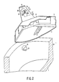
- Fig. 1 diagrammatically shows the parts of a colour display tube before they are assembled to form an envelope. These parts are a display window 1, a shadow mask 2 secured to a frame 3 and a conical enveloping part 4 provided with an electrode system 5 comprising three electron guns.
- the display window 1 is provided with a display screen 6 comprising a large number of phosphor elements luminescing in red, green and blue.
- the phosphor elements may be in the form of, for example, dots or strips.
- the invention will be further described by means of strip-shaped elements the longitudinal direction of which extends perpendicularly to the plane through the electron guns of the electrode system 5 (in this case the plane of the drawing).
- the shadow mask 2 which is provided with a large number of apertures 7, is fixed on a frame 3.
- the electrode system 5 for generating three electron beams is housed in the enveloping part 4 which, by way of example, is conically shaped in the present embodiment but which may be box-shaped in another embodiment of the invention.
- the parts When the parts are accurately positioned relative to one another they are fixed to one another, a glass frit generally being interposed, such that an envelope is formed which is subsequently evacuated.
- a glass frit In fixing and evacuating, in which process the colour display tube is heated to approximately 400°C, it is possible that the shadow mask is moved from its accurate position relative to the display screen.
- this adverse displacement can be compensated by accurately positioning the shadow mask relative to the display window after the envelope is formed, and fixing the adjusted position.
- the method according to the invention enables the position of the shadow mask to be adjusted before the envelope is evacuated, and to fix this position in such a manner that during and after the evacuation process substantially no change occurs in the fixed position.
- Fig. 2 diagrammatically shows a suspension of the shadow mask 2 in the display window 1.
- the display window 1 which is substantially rectangular in the present embodiment, has an upright edge 9 in which a support element in the present embodiment a pin 10 having a free end 21, is provided in each corner.
- the shadow mask 2 is secured to a frame 3 and is provided with a connection element 8 which comprises a resilient element 12 secured to a support strip 11 and a slide plate 13 having an aperture 40 (see Fig. 3).
- the slide plate 13 is provided with a conical portion 14 which engages in a slotted aperture 15 of the flat resilient element 12 with some play.
- the slide plate 13 is provided with two bent lugs 16, 17, which engage with some play in two further slotted apertures 18, 19 which are provided in the flat resilient element 12, and a support portion 20.
- the shadow mask 2 is suspended in the display window 1 in such a manner that the free end 21 projects from the aperture 40 of the slide plate 13 and the conical portion 14 of the slide plate 13 lies against the free end 21 of the pin 10 (see Fig. 3).
- the shadow mask can also be suspended in the display window without making use of a frame. Any tolerances occurring during suspending the shadow mask 2 are compensated by the slide plate 13.
- the resilient element 12 is secured to a positioning element, herein a positioning member 23, which extends through an aperture 26 in the upright edge 9 of the display window 1 into the interior of the display window 1.
- a free end of the positioning member 23 is secured, for example, to a bent portion 22 of the flat resilient element 12, for example, by means a number of laser welds.
- the aperture 26 is sealed in a vacuum tight manner by means of an elastic element 27.
- the conical enveloping part 4 is secured to the display window 1, with glass frit being disposed therebetween, to form an envelope (Fig. 4). It is alternatively possible to secure the positioning elements directly to the shadow mask or to the frame to which the shadow mask is secured. Directely securing the positioning elements to the shadow mask must be carried out with due care to avoid local deformation in the shadow mask during securing and displaying the shadow mask.
- the shadow mask 2 is displaced relative to the display screen 6, and its position can be adjusted in any direction by means of a test pattern which is preferably generated by the electrode system 5 and which impinges on the phosphor elements of the display screen 6 via the apertures 7 of the shadow mask 2 (diagrammatically represented by the electron beams 28, 29 and 30 which are deflected across the display screen 6 by means of a deflection system 31).
- the displacement of the shadow mask 2 is carried out by mechanically moving the positioning members 23, which is made possible by the elastic element, and which movement results in a displacement of the resilient element 12 relative to the slide plate 13 and the pin 10. Due to this, the apertures 7 of the shadow mask 2 move relative to the phosphor elements of the display screen 6.
- a laser beam 32 which is necessary to obtain laser welds is generated by a laser 33 and is passed through a light-transmitting window 34 which is provided in the conical enveloping part 4.
- FIG. 5 An alternative embodiment of a method in accordance with the invention, in which the support elements used to suspend the shadow mask 2 are formed by the positioning members is diagrammatically shown in Fig. 5.
- Each positioning member 50 is provided with a spherical portion 51.
- An aperture 53 and an at least partly spherical recess 54 are formed in a metal annular part 52.
- the positioning member 50 is slid into the aperture 53 until the spherical part 52 lies against the recess 54.
- the aperture 53 is sealed in a vacuum tight manner by means of an elastic element, for example a lead connection 55.
- the metal part 52 and the positioning member 50 are fitted in an aperture 56 of the upright edge 9 of the display window 1 by means of a vacuum tight connection.
- the shadow mask 2 is suspended by securing a bent portion 22 of the resilient element 12 to the positioning member 50.
- a conical enveloping part is secured to the display window 1 such that an envelope is formed which is then evacuated.
- the positioning member 50 can be moved by virtue of the deformability of the lead connection.
- the lead connection can be deformed within certain limits, a vacuum tight connection being maintained.
- the adjusted position is fixed by fixing the free end of the positioning member 50 relative to the upright edge 9, for example, by means of a curing synthetic resin or glass frit.
- FIG. 6 An alternative preferred embodiment of a method in accordance within the invention, in which the shadow mask can be displaced relative to the display window after the envelope is formed, is described by means of Figs. 6 up to an including 10.
- Means 123 are secured with their end 41 to the pin 10 (see Fig. 6). After the shadow mask 2 has been suspended, the other end 42 of the means 123 is secured to the resilient element 12, for example, by means of a number of laser welds.
- the invention is not limited to securing the means 123 to the pin 10.
- the means 123 may for example be secured to the upright edge 9 of the display window 1.
- Means 123 bring about a displacement of the shadow mask 2 relative to the display window 1 as a function of a localised supply of energy to the means 123.
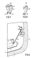
- Figs. 7 and 8 are diagrammatic front views of two embodiments of means 123.
- the means 123 are formed by two juxtaposed, spaced apart, identical metal strips 43 and 44 which are secured with their ends 45, 46 to a pin which is secured in the display window. With their other ends 47 and 48 the metal strips 43 and 44 are fitted to the flat resilient element.
- the means 123 are formed by a bimetal strip 49 which is secured to a pin and a resilient element with its ends 60 and 61, respectively.
- Fig. 9 is a diagrammatic sectional view of an embodiment of a suspension of the shadow mask, which can be displaced relative to the display window.
- Each connection element comprises a resilient element 12 which is secured to the shadow mask 2, and the display window is provided with a pin 10 having a free end 21.
- means 123 are secured to the resilient element 12, for example by means of a number of laser welds at the level of 64.
- a metal part 62 is fitted to the means 123.
- This metal part 62 is provided with a bent portion 63 and a portion 65.
- the shadow mask 2 is suspended in the display window 1 such that the metal part 62 lies against the pin 10 and thet resilient element 12.
- the bent portion 63 prevents the shadow mask 2 from lying against the display screen 6.
- the shadow mask 2 is secured to the display window 1 by securing the portion 65 to the free end 21 of the pin 10, for example by means of a number of laser welds.
- a conical enveloping part 4 is secured to the display window 1, with glass frit being disposed therebetween, such that an envelope is formed which is subsequently evacuated (Fig. 10).
- test pattern is displayed on the display screen 6 by means of the electrode system 5 (diagrammatically represented by the electron beams 25, 26 and 27 which are deflected across the display screen 6 by means of the deflection system 31).
- the test pattern is optimized, for example, as follows.
- the test pattern displayed on the display screen 6 is accurately examined and, dependent on, for example, the colour errors the direction and the magnitude of the displacement of the shadow mask 2 necessary for accurately positioning the apertures 7 of the shadow mask 2 relative to the phosphor elements of the display screen 6 can be determined.
- the displacement of the shadow mask 2 relative to the display window 1 is carried out by locally applying heating energy to the means 123.
- This application of energy can be carried out by means of a laser (not shown) which directs a laser beam to the means 123 via a light-transmitting window in the conical enveloping part 4.
- the energy is preferably applied through an electron beam 32 which is generated by the electrode system 5. In this way an elegant manner of manufacturing a colour display tube is obtained, in which as few elements as possible are used.
- these means By locally applying energy to the means 123, these means are heated locally and, consequently, they expand, thereby causing the means 123 to move.
- the strip 43 If, for example, the embodiment in accordance with Fig. 7 is used and the strip 43 is heated by applying energy the length and shape of strip 43 change relative to the (unheated) strip 44. Owing to this change in length the resilient element 12 in the embodiment shown in Fig. 2 and the slide plate 13 are displaced relative to the pin 10, or in the embodiment shown in Fig. 9 the resilient element is displaced relative to the metal part 62.
- the shape of the means 123 is selected such that a specific desired positional change of the shadow mask 2 relative to the display screen 6 can be obtained by applying energy to a defined spot on the means.
- the means 123 may have many shapes and the shapes shown in the Figures are not to be regarded as limitative.
- the adjusted position of the shadow mask is fixed by securing the resilient element 12, as shown in Fig. 2, to the slide plate 13 by means of a laser beam, and by securing the slide plate 13 to the pin 10 or, as is shown in Fig. 9, by securing the resilient element 12 to the metal part 62.
- the method in accordance with the invention enables, inter alia, an inaccurately aligned shadow mask to be accurately aligned relative to the display window after the colour display tube has been assembled.
Landscapes
- Electrodes For Cathode-Ray Tubes (AREA)
- Manufacture Of Electron Tubes, Discharge Lamp Vessels, Lead-In Wires, And The Like (AREA)
- Formation Of Various Coating Films On Cathode Ray Tubes And Lamps (AREA)
Priority Applications (1)
| Application Number | Priority Date | Filing Date | Title |
|---|---|---|---|
| AT89202029T ATE99453T1 (de) | 1988-08-04 | 1989-08-03 | Verfahren zum herstellen einer farbbildroehre. |
Applications Claiming Priority (2)
| Application Number | Priority Date | Filing Date | Title |
|---|---|---|---|
| NL8801944 | 1988-08-04 | ||
| NL8801944A NL8801944A (nl) | 1988-08-04 | 1988-08-04 | Werkwijze voor het vervaardigen van een kleurenbeeldbuis. |
Publications (2)
| Publication Number | Publication Date |
|---|---|
| EP0355893A1 true EP0355893A1 (de) | 1990-02-28 |
| EP0355893B1 EP0355893B1 (de) | 1993-12-29 |
Family
ID=19852708
Family Applications (1)
| Application Number | Title | Priority Date | Filing Date |
|---|---|---|---|
| EP89202029A Expired - Lifetime EP0355893B1 (de) | 1988-08-04 | 1989-08-03 | Verfahren zum Herstellen einer Farbbildröhre |
Country Status (6)
| Country | Link |
|---|---|
| US (1) | US4950192A (de) |
| EP (1) | EP0355893B1 (de) |
| JP (1) | JPH0268837A (de) |
| AT (1) | ATE99453T1 (de) |
| DE (1) | DE68911792T2 (de) |
| NL (1) | NL8801944A (de) |
Cited By (5)
| Publication number | Priority date | Publication date | Assignee | Title |
|---|---|---|---|---|
| FR2631162A1 (fr) * | 1988-04-07 | 1989-11-10 | Philips Nv | Tube image en couleur et son procede de fabrication |
| EP0503513A1 (de) * | 1991-03-15 | 1992-09-16 | Goldstar Co. Ltd. | Vorrichtung zum Montieren einer Schattenmaske in eine Farbbildröhre |
| EP0512452A1 (de) * | 1991-05-03 | 1992-11-11 | GOLDSTAR CO. Ltd. | Vorrichtung zum Montieren einer Schattenmaske in einer Farbbildröhre |
| CN1041576C (zh) * | 1991-05-03 | 1999-01-06 | 株式会社金星社 | 用于在一个彩色电视显象管内安装荫罩的装置 |
| US7686097B2 (en) | 2005-08-31 | 2010-03-30 | Cnh America Llc | Three point hitch frame, draft arm and rear counterweight design |
Families Citing this family (4)
| Publication number | Priority date | Publication date | Assignee | Title |
|---|---|---|---|---|
| NL9002769A (nl) * | 1990-12-17 | 1992-07-16 | Philips Nv | Werkwijze voor het vervaardigen van een beeldvenster voor een beeldweergave-apparaat. |
| KR100257826B1 (ko) * | 1997-06-09 | 2000-07-01 | 윤종용 | 영상표시장치의 기울기 조정 방법 및 장치 |
| KR100238054B1 (ko) * | 1997-07-04 | 2000-01-15 | 윤종용 | 영상표시장치의 신호 자동공급 방법 및 장치 |
| US6739927B2 (en) * | 2001-01-18 | 2004-05-25 | Matsushita Electric Industrial Co., Ltd. | Method of assembling color crt and assembling device |
Citations (2)
| Publication number | Priority date | Publication date | Assignee | Title |
|---|---|---|---|---|
| EP0180040A2 (de) * | 1984-09-29 | 1986-05-07 | Nokia Graetz Gesellschaft mit beschränkter Haftung | Farbbildröhre |
| NL8800883A (nl) * | 1988-04-07 | 1988-06-01 | Philips Nv | Kleurenbeeldbuis en werkwijze voor het vervaardigen van zulk een kleurenbeeldbuis. |
Family Cites Families (4)
| Publication number | Priority date | Publication date | Assignee | Title |
|---|---|---|---|---|
| US3643299A (en) * | 1969-06-16 | 1972-02-22 | Rca Corp | Electron beam tube and method of adjusting the electrode spacing of an electron gun therein |
| JPS6489246A (en) * | 1987-09-30 | 1989-04-03 | Sony Corp | Fixing method for color sorting mechanism of color cathode-ray tube |
| US4866334A (en) * | 1988-05-10 | 1989-09-12 | Zenith Electronics Corporation | CRT faceplate front assembly with rigidized tension mask support structure |
| US7373951B2 (en) * | 2004-09-07 | 2008-05-20 | Fisher Controls International Llc | Control valve having “C” seal |
-
1988
- 1988-08-04 NL NL8801944A patent/NL8801944A/nl not_active Application Discontinuation
-
1989
- 1989-08-03 DE DE68911792T patent/DE68911792T2/de not_active Expired - Fee Related
- 1989-08-03 AT AT89202029T patent/ATE99453T1/de not_active IP Right Cessation
- 1989-08-03 EP EP89202029A patent/EP0355893B1/de not_active Expired - Lifetime
- 1989-08-04 JP JP1201459A patent/JPH0268837A/ja active Pending
- 1989-08-04 US US07/389,670 patent/US4950192A/en not_active Expired - Fee Related
Patent Citations (2)
| Publication number | Priority date | Publication date | Assignee | Title |
|---|---|---|---|---|
| EP0180040A2 (de) * | 1984-09-29 | 1986-05-07 | Nokia Graetz Gesellschaft mit beschränkter Haftung | Farbbildröhre |
| NL8800883A (nl) * | 1988-04-07 | 1988-06-01 | Philips Nv | Kleurenbeeldbuis en werkwijze voor het vervaardigen van zulk een kleurenbeeldbuis. |
Non-Patent Citations (1)
| Title |
|---|
| PATENT ABSTRACTS OF JAPAN, vol. 7, no. 4 (E-151)[1149], 8th January 1983, page 110 E 151; & JP-A-57 163 951 (TOKYO SHIBAURA DENKI K.K.) 08-10-1982 * |
Cited By (5)
| Publication number | Priority date | Publication date | Assignee | Title |
|---|---|---|---|---|
| FR2631162A1 (fr) * | 1988-04-07 | 1989-11-10 | Philips Nv | Tube image en couleur et son procede de fabrication |
| EP0503513A1 (de) * | 1991-03-15 | 1992-09-16 | Goldstar Co. Ltd. | Vorrichtung zum Montieren einer Schattenmaske in eine Farbbildröhre |
| EP0512452A1 (de) * | 1991-05-03 | 1992-11-11 | GOLDSTAR CO. Ltd. | Vorrichtung zum Montieren einer Schattenmaske in einer Farbbildröhre |
| CN1041576C (zh) * | 1991-05-03 | 1999-01-06 | 株式会社金星社 | 用于在一个彩色电视显象管内安装荫罩的装置 |
| US7686097B2 (en) | 2005-08-31 | 2010-03-30 | Cnh America Llc | Three point hitch frame, draft arm and rear counterweight design |
Also Published As
| Publication number | Publication date |
|---|---|
| DE68911792D1 (de) | 1994-02-10 |
| DE68911792T2 (de) | 1994-07-07 |
| EP0355893B1 (de) | 1993-12-29 |
| ATE99453T1 (de) | 1994-01-15 |
| NL8801944A (nl) | 1990-03-01 |
| US4950192A (en) | 1990-08-21 |
| JPH0268837A (ja) | 1990-03-08 |
Similar Documents
| Publication | Publication Date | Title |
|---|---|---|
| US4387321A (en) | Color display tube and suspension means for color selection electrode | |
| US4437036A (en) | Cathode-ray tube having a temperature compensated mask-frame assembly | |
| US5003218A (en) | Color display tube and method of manufacturing such a color display tube | |
| EP0431693B1 (de) | Farbbildröhre | |
| US3986071A (en) | Resilient clamping members for color selection electrode | |
| US4950192A (en) | Method of manufacturing of color display tube | |
| US2846608A (en) | Cathode-ray tube | |
| EP0332262B1 (de) | Verfahren zur Herstellung einer Farbkathodenstrahlröhre und Farbkathodenstrahlröhre | |
| GB2052148A (en) | Colour cathode ray tubes | |
| US4964828A (en) | Method of manufacturing a color display tube and a color display tube | |
| US3806108A (en) | Work holder for assembling a cathode ray tube envelope | |
| US5350970A (en) | Display tube having a detachable getter | |
| EP0295732B1 (de) | Verfahren zum Herstellen einer Elektronenkanone | |
| US5256937A (en) | Flat panel fluorescent screen display tube | |
| US6271624B1 (en) | Cathode ray tube having a fag with spring holder | |
| US4605878A (en) | Supporting device for an electron beam landing position selecting mask of a color cathode ray tube | |
| US6013975A (en) | Color display tube having a shadow mask | |
| EP0251404B1 (de) | Verfahren zur Herstellung einer Kathodestrahlröhre | |
| JPS598245A (ja) | カラ−映像管用細隙型シヤド−マスクの製造法 | |
| US5140218A (en) | Cathode ray tube comprising an electron gun | |
| EP0644571B1 (de) | Farbbildröhre mit Schattenmaskerahmenträger | |
| US4573935A (en) | Sealing fixture for color kinescopes | |
| US4507873A (en) | Apparatus for accurately establishing the sealing length of CRT envelopes | |
| US4872863A (en) | Method of fixing a cathode-ray tube cone and display window prior to sealing and a cathode-ray tube manfactured by such a method | |
| US6239544B1 (en) | Flat-type image display apparatus with insulating positioning members |
Legal Events
| Date | Code | Title | Description |
|---|---|---|---|
| PUAI | Public reference made under article 153(3) epc to a published international application that has entered the european phase |
Free format text: ORIGINAL CODE: 0009012 |
|
| AK | Designated contracting states |
Kind code of ref document: A1 Designated state(s): AT DE ES FR GB IT NL |
|
| 17P | Request for examination filed |
Effective date: 19900822 |
|
| 17Q | First examination report despatched |
Effective date: 19920820 |
|
| GRAA | (expected) grant |
Free format text: ORIGINAL CODE: 0009210 |
|
| AK | Designated contracting states |
Kind code of ref document: B1 Designated state(s): AT DE ES FR GB IT NL |
|
| PG25 | Lapsed in a contracting state [announced via postgrant information from national office to epo] |
Ref country code: NL Effective date: 19931229 Ref country code: ES Free format text: THE PATENT HAS BEEN ANNULLED BY A DECISION OF A NATIONAL AUTHORITY Effective date: 19931229 Ref country code: AT Effective date: 19931229 |
|
| REF | Corresponds to: |
Ref document number: 99453 Country of ref document: AT Date of ref document: 19940115 Kind code of ref document: T |
|
| REF | Corresponds to: |
Ref document number: 68911792 Country of ref document: DE Date of ref document: 19940210 |
|
| ITF | It: translation for a ep patent filed | ||
| ET | Fr: translation filed | ||
| NLV1 | Nl: lapsed or annulled due to failure to fulfill the requirements of art. 29p and 29m of the patents act | ||
| PLBE | No opposition filed within time limit |
Free format text: ORIGINAL CODE: 0009261 |
|
| STAA | Information on the status of an ep patent application or granted ep patent |
Free format text: STATUS: NO OPPOSITION FILED WITHIN TIME LIMIT |
|
| 26N | No opposition filed | ||
| ITPR | It: changes in ownership of a european patent |
Owner name: CAMBIO RAGIONE SOCIALE;PHILIPS ELECTRONICS N.V. |
|
| REG | Reference to a national code |
Ref country code: FR Ref legal event code: CD |
|
| PGFP | Annual fee paid to national office [announced via postgrant information from national office to epo] |
Ref country code: GB Payment date: 19960731 Year of fee payment: 8 |
|
| PGFP | Annual fee paid to national office [announced via postgrant information from national office to epo] |
Ref country code: FR Payment date: 19960828 Year of fee payment: 8 |
|
| PGFP | Annual fee paid to national office [announced via postgrant information from national office to epo] |
Ref country code: DE Payment date: 19961025 Year of fee payment: 8 |
|
| PG25 | Lapsed in a contracting state [announced via postgrant information from national office to epo] |
Ref country code: GB Free format text: LAPSE BECAUSE OF NON-PAYMENT OF DUE FEES Effective date: 19970803 |
|
| GBPC | Gb: european patent ceased through non-payment of renewal fee |
Effective date: 19970803 |
|
| PG25 | Lapsed in a contracting state [announced via postgrant information from national office to epo] |
Ref country code: FR Free format text: LAPSE BECAUSE OF NON-PAYMENT OF DUE FEES Effective date: 19980430 |
|
| PG25 | Lapsed in a contracting state [announced via postgrant information from national office to epo] |
Ref country code: DE Free format text: LAPSE BECAUSE OF NON-PAYMENT OF DUE FEES Effective date: 19980501 |
|
| REG | Reference to a national code |
Ref country code: FR Ref legal event code: ST |
|
| PG25 | Lapsed in a contracting state [announced via postgrant information from national office to epo] |
Ref country code: IT Free format text: LAPSE BECAUSE OF NON-PAYMENT OF DUE FEES Effective date: 20050803 |