EP0356151B1 - Dispositif d'avance centrifuge - Google Patents
Dispositif d'avance centrifuge Download PDFInfo
- Publication number
- EP0356151B1 EP0356151B1 EP19890308367 EP89308367A EP0356151B1 EP 0356151 B1 EP0356151 B1 EP 0356151B1 EP 19890308367 EP19890308367 EP 19890308367 EP 89308367 A EP89308367 A EP 89308367A EP 0356151 B1 EP0356151 B1 EP 0356151B1
- Authority
- EP
- European Patent Office
- Prior art keywords
- weights
- travel
- driving shaft
- cam member
- mechanism according
- Prior art date
- Legal status (The legal status is an assumption and is not a legal conclusion. Google has not performed a legal analysis and makes no representation as to the accuracy of the status listed.)
- Expired - Lifetime
Links
Images


Classifications
-
- F—MECHANICAL ENGINEERING; LIGHTING; HEATING; WEAPONS; BLASTING
- F02—COMBUSTION ENGINES; HOT-GAS OR COMBUSTION-PRODUCT ENGINE PLANTS
- F02P—IGNITION, OTHER THAN COMPRESSION IGNITION, FOR INTERNAL-COMBUSTION ENGINES; TESTING OF IGNITION TIMING IN COMPRESSION-IGNITION ENGINES
- F02P5/00—Advancing or retarding ignition; Control therefor
- F02P5/04—Advancing or retarding ignition; Control therefor automatically, as a function of the working conditions of the engine or vehicle or of the atmospheric conditions
- F02P5/05—Advancing or retarding ignition; Control therefor automatically, as a function of the working conditions of the engine or vehicle or of the atmospheric conditions using mechanical means
- F02P5/06—Advancing or retarding ignition; Control therefor automatically, as a function of the working conditions of the engine or vehicle or of the atmospheric conditions using mechanical means dependent on engine speed
-
- F—MECHANICAL ENGINEERING; LIGHTING; HEATING; WEAPONS; BLASTING
- F02—COMBUSTION ENGINES; HOT-GAS OR COMBUSTION-PRODUCT ENGINE PLANTS
- F02B—INTERNAL-COMBUSTION PISTON ENGINES; COMBUSTION ENGINES IN GENERAL
- F02B1/00—Engines characterised by fuel-air mixture compression
- F02B1/02—Engines characterised by fuel-air mixture compression with positive ignition
- F02B1/04—Engines characterised by fuel-air mixture compression with positive ignition with fuel-air mixture admission into cylinder
Definitions
- This invention relates to a centrifugal advance mechanism, particularly such mechanism for use in the distributor of an ignition system of an internal combustion engine.
- Centrifugal advance mechanisms in the control of the ignition timing of internal combustion engines are well known.
- the mechanism has a plurality of rotating weights, usually two, which travel under centrifugal force outwardly from the axis of a driving shaft against the action of resilient means, usually helical springs, urging the weights inwardly.
- the weights carry driving cam members which act upon a driven cam member which is thus driven in rotation by the weights.
- the relative rotational position of the driven cam member and the driving shaft is determined by the radial position of the weights relative to the driving shaft.
- the rotational position of an output shaft connected to the driven cam member relative to the driving shaft is determined by the rotational speed of the driving shaft.
- Such a mechanism advances the ignition timing in dependence upon the rotational speed of the engine. In principle, it might be used to retard the rotational position of the output shaft, and the invention is applicable to such an arrangement. However, it will here be described in connection with the advancement of the output shaft, as in ignition timing.
- the reason for ignition timing advance in an internal combustion engine is that, when a spark plug fires in the engine, the petrol-air mixture takes some time to achieve complete combustion. Therefore, at high engine speeds, the ignition timing should be advanced to cause the plug to fire before the piston reaches the top dead centre position. The ignition timing will therefore vary with the engine speed, and this is achieved automatically using a centrifugal advance mechanism.
- Fig. 11 of the accompanying drawings shows the construction of a conventional centrifugal advance mechanism used in a distributor.
- Fixed on a driving shaft 1 is a plate 2 carrying pivots 3 for two weights 5.
- Springs 11 extend between spring pins 4 on the plate 2 and spring pins 7 on the weights 5, and act to pivot the weights inwardly towards the shaft axis 1 about the weight pivots 3.
- the weights carry driving cam members in the form of pins 6 extending parallel to the axis of the shaft 1 and engaged in cam holes 10 in the driven timing lever 8.
- the timing lever 8 is fixed to the output shaft 9 which is mounted on but freely rotatable around the driving shaft 1.
- the conventional centrifugal advance mechanism described above has been designed without consideration for the effect of rapid fluctuation in the angular velocity of the driving shaft, i.e. angular accelerations and decelerations of the driving shaft.
- Such accelerations have in recent years greatly increased, with the use of lighter and more powerful petrol engines, and cause very rapid variation of angular velocity even during one rotation. It can be said that ten years ago this angular acceleration was of the order of 2000 to 3000 radians/s 2 , whereas in recent engines and engines under development, it may amount to 120000 radians/s 2.
- This variation of angular acceleration arises from the engine cycle, i.e. compression and combustion in the several cylinders.
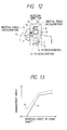
- Fig. 13 illustrates the case without angular acceleration, whereas the increased advance angle caused by the deceleration of the shaft 1 is indicated by broken line b.
- This increased advance causes deterioration in the combustion in the engine, resulting in the phenomonon of knocking.
- Fig. 13 indicates that the difference of the advance angle from the design characteristic is larger when the rotational speed (angular velocity) of the drive shaft 1 is smaller, i.e. the angular acceleration variation has particularly bad effect on the advance angle at low rotational speeds.
- the additional element is a "stabiliser ring" which is an extra plate mounted on the shaft axis 1 and free to rotate, and having curved slots receiving the weight pins 6. These slots intersect the slots 10 in the timing plate at an angle, with the result that the inertial forces of the stabiliser ring and the timing plate clamp the weight pins during acceleration of the shaft 1, preventing movement of the weights under the influence of such acceleration.
- this device suffers from the defect that the weight pins which are contacted by the timing lever and by the stabiliser ring suffer rapid and uneven wear, and become unsatisfactorily deformed.
- the object of this invention is to overcome, at least partly, the problem just described and to provide a centrifugal advance mechanism that has highly stable advance characteristics regardless of the variation of angular acceleration of the driving shaft.
- the invention is set out in claims 1 and 8.
- the stabiliser ring device described above uses an extra element to control the effect of the acceleration on the weights, while the present invention achieves this through the geometry of the weights and the interacting cam surfaces.
- the geometry of the weights is selected so that the effect of the angular deceleration of the driving shaft is opposite to that in the conventional advance mechanism described above.
- the weights have concave surfaces facing radially outwardly from the driving shaft axis.
- the effect of the inertial forces arising upon angular deceleration urges the weights inwardly over at least 50%, more preferably 80%, of the radial travel of the weights. It is even possible to arrange the weights so that this effect of the inertial forces urges the weights inwardly over the whole of the travel of the weights.
- the influence of the angular deceleration is particularly great at low engine speeds, and accordingly it is preferred that the portion of the travel of the weights at which the inertial forces urge the weights inwardly includes the radially inner end portion of the travel of the weights.
- the effect of the inertial forcxe of the weights at the weight pivots is of course determined by the shape of the weights.
- the geometry of the cam surfaces is chosen to achieve the desired result of controlling the effect of the inertial force arising upon acceleration or decelreation of the driving shaft.
- the portion of the travel of the weights at which the inertial force of the driven cam member does not act to cause movement of the weights is preferably at the radially inner end of the travel of the weights, where the effect of the acceleration upon the timing advance characteristics is greatest, but there may be two such portions of the travel of the weights, one at the radially inner end of the travel and the other at a radially outer region of the travel of the weights.
- Figs. 1 to 7 showing the centrifugal advance mechanism embodying the invention, the reference numbers 1 - 12 are used for the parts corresponding in function and name to the parts having the same reference numbers in the conventional device of Fig. 11. These parts need not be described again except to explain how they differ.
- the centre of gravity 12 of each weight 5 is located as shown in Fig. 3, so that the tangent line to the arc around the axis of the driving shaft 1 passing through the centre of gravity 12, this tangent line extending from the centre of gravity 12 towards the weight pivot 3, lies between the axis of the driving shaft 1 and the line connecting the centre of gravity 12 and the weight pivot 3.
- the shape of the weights 5 and the position of the weight pivots 3 are determined so as to achieve this result.
- the angle between (i) the radius line joining the centre of gravity 12 of the weight to the driving shaft axis 1 and (ii) the line joining the centre of gravity 12 of the weight to the pivot axis 3 is greater than 90 °, over a range of radial positions of the weight including the inner end of the travel of the weight. This range is in practice more than 80% of the weights' travel but as the weight swings around the pivot 3 this angle decreases and may come below 90 °. It can be seen from Figs. 1 and 3 that the outer surfaces of the weights 5 facing away from the shaft 1 are concave, which helps to locate the centre of gravity 12 in the desired position.
- the cam holes 10 in the timing lever 8 have the shape shown in Figs. 4,5,6 and 7 which is determined so that the angle 6w between (i) the common normal line at the contact point of the weight pin 6 and the edge of the cam hole 10 and (ii) the direction of movement Mw of the weight 5 around the pivot axis 3 at this contact point is large (Fig. 4).
- the angle et between (i) the common normal line at the contact point of the weight pin 6 and the edge of the cam hole 10 and (ii) the direction of movement Mt of the timing lever 8 around the axis of the shaft 1 at this contact point is small (Fig. 5).
- the force F arising between the weight 5 and the timing lever 8 is equal to the normal force N that acts in the direction of the common normal line at the contact point of the weight pin 6 and the cam hole 10.
- the component of the normal force N applied by the timing lever 8 to move the weight 5 along the hole 10 is N.cosew.
- the component of the normal force N applied by the weight 5 to move the timing lever 8 in rotation about the shaft 1 is N.coset.
- the basic function of the centrifugal advance mechanism i.e. the advance characteristic has to be determined only by the centrifugal force generated in the weight 5.
- the advance characteristic should be determined by the rotational speed of the driving shaft 1.
- the weight pin 6 should freely drive the timing lever 8, but the weight pin 6, i.e. the weight 5, should not be easily driven by the moment of the inertial force of the timing lever 8.
- the region of large rate of advance is particularly where the rotational speed (angular velocity) of the driving shaft is low, that is when the advance is small. Consequently the cam hole 10 is shaped so that the angle 6w between the resultant force F and the direction of motion Mw of the weight 5 is extraordinarily large.
- ⁇ max is taken to be the maximum conceivable coefficient of friction between the cam hole 10 and the weight pin 6 during designing.
- the necessary condition for the weight pin 6 to drive the timing lever 8 is cos ⁇ t>0, that is ⁇ t ⁇ 90 ° .
- the necessary condition for the weight pin 6 not to be driven by the timing lever 8 is cos ⁇ w ⁇ O, that is ⁇ w>90 ° .
- Fig. 8 represents the value of the maximum coefficient of friction ⁇ max and the values of et and 6w as explained above.
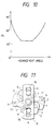
- Fig. 9 and Fig. 10 show et and 6w respectively against advance angle for the profile of the cam hole 10 in this embodiment of the invention.
- Fig. g shows generally a small value for et of -30 ° ⁇ t ⁇ 30 ° .
- Fig. 10 shows a value for ⁇ w as much as 30 ° ⁇ w ⁇ 90 °.
- Fig. 10 also shows that 0w is close to 90 °, i.e. an especially large value, at the region of small advance angle where a large rate of advance often occurs.
- Figs. 9 and 10 show that at a region including the radially inner end (small advance angle) of the travel of the weights and at a further large advance region remote from the radially inner end, et is close to zero, i.e. -15 ° ⁇ t ⁇ 15 ° .
- et is close to zero, i.e. -15 ° ⁇ t ⁇ 15 ° .
- ⁇ w approaches 90°, i.e. 60 ° ⁇ ⁇ w ⁇ 120 ° .
- Preferably in these regions 80 ° ⁇ w ⁇ 100 ° more preferably 85° ⁇ w ⁇ 95°.
- the profile of the cam hole shown in Figs. 1, 9 and 10 is only one example of the invention.
- the invention disclosed can generally be applied to achieve stable advance characteristics in centrifugal advance mechanisms of various advance characteristics, regardless of the variation of angular acceleration of the driving shaft.
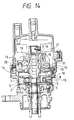
- Fig. 14 is an overall view of an automotive distributor in which the centrifugal advance mechanism of this invention is applied.
- Fig. 14 shows a coupler 14 of a vacuum advance control mechanism (not illustrated) which adjusts ignition timing according to the load conditions of the engine (i.e. according to inlet manifold vacuum).
- the distributor has a stationary base 15 fixed to the distributor body 13.
- the coupler 14 is connected to a mobile base 16 that is mounted on the stationary base 15, but can rotate freely under the action of the coupler 14.
- a magnet 17 and a stator core 18 are fixed to the mobile base 16.
- the stationary base 15 has a ignition timing control device 20 with a detector coil 19.
- the engine drives the driving shaft 1 which is inserted into the rotor shaft 9.
- the rotor shaft 9 is housed together with retractors 21.
- the magnetic flux through the magnetic path composed of the magnet 17, the stator core 18, the retractor 21, the rotor shaft 9, and the mobile base 16, changes.
- This change of the magnetic flux generates a signal voltage at the detector coil 19, and through the signal voltage, the ignition timing control device 20 determines the spark timing. In a conventional manner this signal voltage alternates the time of generation and ignition in compliance with the vacuum advance control mechanism and the centrifugal advance mechanism of this invention.
- the centrifugal advance mechanism of this invention can provide stable advance characteristics with little or no effect caused by the angular acceleration fluctuation of the engine. Ignition timing is controlled properly and combustion improved.
Landscapes
- Engineering & Computer Science (AREA)
- Chemical & Material Sciences (AREA)
- Combustion & Propulsion (AREA)
- Mechanical Engineering (AREA)
- General Engineering & Computer Science (AREA)
- High-Pressure Fuel Injection Pump Control (AREA)
- Valve Device For Special Equipments (AREA)
- Connection Of Motors, Electrical Generators, Mechanical Devices, And The Like (AREA)
- One-Way And Automatic Clutches, And Combinations Of Different Clutches (AREA)
Claims (17)
Applications Claiming Priority (2)
| Application Number | Priority Date | Filing Date | Title |
|---|---|---|---|
| JP20471988A JPH07101026B2 (ja) | 1988-08-19 | 1988-08-19 | ガバナ進角装置 |
| JP204719/88 | 1988-08-19 |
Publications (3)
| Publication Number | Publication Date |
|---|---|
| EP0356151A2 EP0356151A2 (fr) | 1990-02-28 |
| EP0356151A3 EP0356151A3 (fr) | 1991-02-20 |
| EP0356151B1 true EP0356151B1 (fr) | 1994-11-30 |
Family
ID=16495177
Family Applications (1)
| Application Number | Title | Priority Date | Filing Date |
|---|---|---|---|
| EP19890308367 Expired - Lifetime EP0356151B1 (fr) | 1988-08-19 | 1989-08-17 | Dispositif d'avance centrifuge |
Country Status (3)
| Country | Link |
|---|---|
| EP (1) | EP0356151B1 (fr) |
| JP (1) | JPH07101026B2 (fr) |
| DE (1) | DE68919586T2 (fr) |
Families Citing this family (1)
| Publication number | Priority date | Publication date | Assignee | Title |
|---|---|---|---|---|
| CN102011670B (zh) * | 2010-11-05 | 2012-05-23 | 长春市长铃技术开发有限公司 | 一种可自动改变点火提前角的装置 |
-
1988
- 1988-08-19 JP JP20471988A patent/JPH07101026B2/ja not_active Expired - Lifetime
-
1989
- 1989-08-17 EP EP19890308367 patent/EP0356151B1/fr not_active Expired - Lifetime
- 1989-08-17 DE DE1989619586 patent/DE68919586T2/de not_active Expired - Fee Related
Also Published As
| Publication number | Publication date |
|---|---|
| DE68919586D1 (de) | 1995-01-12 |
| JPH0255875A (ja) | 1990-02-26 |
| JPH07101026B2 (ja) | 1995-11-01 |
| EP0356151A3 (fr) | 1991-02-20 |
| DE68919586T2 (de) | 1995-05-24 |
| EP0356151A2 (fr) | 1990-02-28 |
Similar Documents
| Publication | Publication Date | Title |
|---|---|---|
| EP2249000B1 (fr) | Dispositif de variation de phase dans un moteur d'automobile | |
| KR100910371B1 (ko) | 마찰 클러치 | |
| US5092195A (en) | Balancers | |
| EP0356151A2 (fr) | Dispositif d'avance centrifuge | |
| US3220395A (en) | Distributor having advance and retard control | |
| US2829507A (en) | Coupling | |
| US3791171A (en) | Centrifugal governor particularly for altering the moment of injection start in diesel engines | |
| US3424875A (en) | Distributor spark advance mechanism | |
| US4250859A (en) | Adjusting mechanism for the rotational speed-dependent control of the injection instant of an injection pump of internal combustion engines | |
| US4535737A (en) | Centrifugal spark-advance controlling device | |
| JP2007085369A (ja) | フライホイール | |
| JP4166644B2 (ja) | 内燃機関のバルブタイミング制御装置 | |
| US4677914A (en) | Safety device for a spinning projectile fuze | |
| EP0656094B1 (fr) | Mecanisme de changement de phase | |
| JPS5830126Y2 (ja) | 遠心進角装置 | |
| US4183230A (en) | Centrifugal governor for engine ignition system | |
| JPS587104Y2 (ja) | 無接点式点火装置 | |
| JP2503394B2 (ja) | 内燃機関用燃料噴射時期調整装置 | |
| US4291628A (en) | Safety mechanism for fuses | |
| JPS6347655Y2 (fr) | ||
| JPH0218369Y2 (fr) | ||
| JPS5912161A (ja) | 機関点火時期制御装置 | |
| JP3820083B2 (ja) | 噴射時期調整タイマー装置 | |
| CA1104892A (fr) | Traduction non-disponible | |
| JPH052431A (ja) | 内燃機関用遠心力調速機 |
Legal Events
| Date | Code | Title | Description |
|---|---|---|---|
| PUAI | Public reference made under article 153(3) epc to a published international application that has entered the european phase |
Free format text: ORIGINAL CODE: 0009012 |
|
| 17P | Request for examination filed |
Effective date: 19891003 |
|
| AK | Designated contracting states |
Kind code of ref document: A2 Designated state(s): DE FR GB IT NL |
|
| PUAL | Search report despatched |
Free format text: ORIGINAL CODE: 0009013 |
|
| AK | Designated contracting states |
Kind code of ref document: A3 Designated state(s): DE FR GB IT NL |
|
| 17Q | First examination report despatched |
Effective date: 19930625 |
|
| GRAA | (expected) grant |
Free format text: ORIGINAL CODE: 0009210 |
|
| AK | Designated contracting states |
Kind code of ref document: B1 Designated state(s): DE FR GB IT NL |
|
| PG25 | Lapsed in a contracting state [announced via postgrant information from national office to epo] |
Ref country code: IT Free format text: LAPSE BECAUSE OF FAILURE TO SUBMIT A TRANSLATION OF THE DESCRIPTION OR TO PAY THE FEE WITHIN THE PRE;WARNING: LAPSES OF ITALIAN PATENTS WITH EFFECTIVE DATE BEFORE 2007 MAY HAVE OCCURRED AT ANY TIME BEFORE 2007. THE CORRECT EFFECTIVE DATE MAY BE DIFFERENT FROM THE ONE RECORDED.SCRIBED TIME-LIMIT Effective date: 19941130 Ref country code: NL Effective date: 19941130 Ref country code: FR Effective date: 19941130 |
|
| REF | Corresponds to: |
Ref document number: 68919586 Country of ref document: DE Date of ref document: 19950112 |
|
| EN | Fr: translation not filed | ||
| NLV1 | Nl: lapsed or annulled due to failure to fulfill the requirements of art. 29p and 29m of the patents act | ||
| PLBE | No opposition filed within time limit |
Free format text: ORIGINAL CODE: 0009261 |
|
| STAA | Information on the status of an ep patent application or granted ep patent |
Free format text: STATUS: NO OPPOSITION FILED WITHIN TIME LIMIT |
|
| 26N | No opposition filed | ||
| REG | Reference to a national code |
Ref country code: GB Ref legal event code: IF02 |
|
| PGFP | Annual fee paid to national office [announced via postgrant information from national office to epo] |
Ref country code: GB Payment date: 20020807 Year of fee payment: 14 |
|
| PGFP | Annual fee paid to national office [announced via postgrant information from national office to epo] |
Ref country code: DE Payment date: 20021024 Year of fee payment: 14 |
|
| PG25 | Lapsed in a contracting state [announced via postgrant information from national office to epo] |
Ref country code: GB Free format text: LAPSE BECAUSE OF NON-PAYMENT OF DUE FEES Effective date: 20030817 |
|
| PG25 | Lapsed in a contracting state [announced via postgrant information from national office to epo] |
Ref country code: DE Free format text: LAPSE BECAUSE OF NON-PAYMENT OF DUE FEES Effective date: 20040302 |
|
| GBPC | Gb: european patent ceased through non-payment of renewal fee |
Effective date: 20030817 |