EP0356575A2 - Dispositif de serrage pour tour - Google Patents
Dispositif de serrage pour tour Download PDFInfo
- Publication number
- EP0356575A2 EP0356575A2 EP88116482A EP88116482A EP0356575A2 EP 0356575 A2 EP0356575 A2 EP 0356575A2 EP 88116482 A EP88116482 A EP 88116482A EP 88116482 A EP88116482 A EP 88116482A EP 0356575 A2 EP0356575 A2 EP 0356575A2
- Authority
- EP
- European Patent Office
- Prior art keywords
- insert
- collet
- clamping device
- clamping
- nut
- Prior art date
- Legal status (The legal status is an assumption and is not a legal conclusion. Google has not performed a legal analysis and makes no representation as to the accuracy of the status listed.)
- Withdrawn
Links
- 238000003780 insertion Methods 0.000 claims description 2
- 230000037431 insertion Effects 0.000 claims description 2
- 230000002349 favourable effect Effects 0.000 description 1
- 238000009434 installation Methods 0.000 description 1
- 238000004519 manufacturing process Methods 0.000 description 1
- 230000013011 mating Effects 0.000 description 1
Images


Classifications
-
- B—PERFORMING OPERATIONS; TRANSPORTING
- B23—MACHINE TOOLS; METAL-WORKING NOT OTHERWISE PROVIDED FOR
- B23B—TURNING; BORING
- B23B31/00—Chucks; Expansion mandrels; Adaptations thereof for remote control
- B23B31/02—Chucks
- B23B31/10—Chucks characterised by the retaining or gripping devices or their immediate operating means
- B23B31/12—Chucks with simultaneously-acting jaws, whether or not also individually adjustable
- B23B31/20—Longitudinally-split sleeves, e.g. collet chucks
- B23B31/208—Longitudinally-split sleeves, e.g. collet chucks with a tool positioning stop
Definitions
- the invention relates to a clamping device for clamping a workpiece on a lathe, in particular an NC lathe, in which a slotted collet with an end face rests on a flange of a headstock and is acted upon by a axially movable clamping sleeve via a cone and at the end Clamping jaws limit a mounting hole, the slots extend far beyond the jaws and an unslotted ring area connects to the slots.
- the invention is therefore based on the object of designing a clamping device of the type mentioned in such a way that an axial positioning of a workpiece is provided in a manner that is simple to assemble and does not impair the collet.
- the invention provides that a distance behind the jaws in the clamping pliers arranged insert, which carries a coaxial, preferably adjustable stop for the workpiece to the receiving bore, is releasably attachable to the unslotted ring area by the insert screw-in, which is screwed into a counter thread, is supported with a radial step on the end of the collet opposite the end face.
- the radial step and the back end are flat surfaces oriented essentially perpendicular to the axis of the collet, it has proven to be particularly advantageous if the radial step has a conical centering ring groove which has a conical counter surface on the back end and acts radially in a clamping manner having.
- cone does not only mean that it is a matter of conical surface sections which, moreover, have the same design on both parts.
- convex curved sections or sections of different curvature of which the concave section at the back end of the collet has a larger radius of curvature than the convex counter "cone" section at the radial step.
- the releasable connection of the insert can take place in such a way that the insert can be screwed directly into the unslotted ring area provided with an internal thread.
- the insert can also be screwed into an insert nut attached to the unslit ring area, this insert nut directly inside the unslit one Ring area could be provided.
- an embodiment can be used in which the insert nut protrudes with radial lugs into the slots of the collet, which when screwed in - with the unslotted ring area between the lugs and the radial step jamming - against the bottom of the slots.
- the insert piece is cup-shaped with an open end piece and a closed end formed with the open end piece is screwed into the insert thread, in particular the insert nut, and carries the stop at the closed end.
- the outer diameter of the insert nut is slightly smaller than the diameter of the collet in the unslotted ring area and in the subsequent slotted area and that two of the lugs each have a bevel for insertion the slanted insert nut are provided in the unslit ring area.
- an end region of the insert forming the step has axially extending engagement grooves on the outside.
- a hook wrench which serves to screw the insert in firmly, engages these engagement grooves.
- the stop is provided on a rod which is axially adjustable relative to the cup-like insert and can be fixed thereon by means of a locking nut. This is a simple way to position the stop axially in order to be able to fix workpieces with different depths into the collet.
- the rod is screwed into a thread in the base at the closed end of the cup-shaped insert and carries a lock nut which presses against the back end.
- This adjustable setting of the rod is less expensive.
- the rod is seated in a slotted auxiliary collet which is supported by a cone on the base of the cup-shaped insert and carries a clamping nut which presses against the back end.
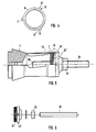
- the clamping device has a headstock 1, which is seated on an NC lathe, not shown, and forms a flange 2 projecting radially inwards toward the front.
- An end face 3 of a collet 4 is pressed against the flange 2, the flange engaging in an annular recess 5 on the end face.
- the collet 4, which is hollowed along its length, is provided with three slots 6, which are evenly distributed over the circumference and extend from the end face 3 to the rear and end at an unslit ring area 7.
- a slit slit located in front of the ring area 7 is designed as a widening 8.
- the collet 4 forms three jaws 9 at the front at the front side 3, which limit a receiving bore 10 and form a cone 11 in the region of the jaws, which tapers away from the front side 3 towards the rear.
- a collet 12 is seated, which on the inside forms a cone 13 which presses against the cone 11 of the collet.
- the clamping sleeve 12 is acted upon by a clamping tube 14, which can be pressed with a device, not shown, in the direction in front of the end face 3 in order to clamp a workpiece, not shown, by means of the collet 4.
- An insert nut 16 is provided, which is an internally threaded, externally round ring structure which has three radially outwardly projecting lugs 17, 18, 19 which are uniformly distributed over the circumference.
- the insert nut 16 is arranged at the rear end of the slots 6 and the lugs 17, 18, 19 rest on the rear base 20 of the slots. Since the slots 6 form the widening 8 towards the rear, the lugs 17, 18, 19 can be correspondingly wide in the circumferential direction, which improves the strength of the lugs.
- the lugs 17, 18, 19 have the same width in the axial direction as the insert nut 16.
- the outer diameter of the insert nut 16 is on both sides by a gap 21 smaller than the inner diameter of the collet 4.
- the two lugs 18, 19 are provided with a chamfer 22, the two chamfers running parallel to one another and the distance between the two chamfers slightly, e.g. 0.5 mm, is larger than the outer diameter of the insert nut 16.
- a cup-like insert 23 with an elongated threaded region 24 is screwed into the insert nut 16 and is at least twice as long in the axial direction as the insert nut is wide.
- the threaded area 24 merges via a radially outward step into a guide area 42 which fits exactly or with play in the ring area 7 of the collet 4 and together with the threaded area forms the wall of the cup.
- the insert piece 23 with an end area 25 forms a radially outwardly directed step 26 which engages behind a rear end 27 of the collet 4.
- the end region 25 is provided with axially extending engagement grooves 28 distributed over the circumference.
- the insert 23 is located with the end region 25 forming the base of the cup outside the collet 4.
- a rod 29 protrudes through the middle of the bowl and forms a stop 30 in the insert 23.
- the rod 29 is screwed with an outer thread 31 into an inner thread in the end region 25 of the insert piece 23, so that the position of the stop 30 can be changed by turning the rod 29.
- a lock nut 32 which is screwed against the end region 25 and fixes the rod.
- the externally smooth rod 29 is seated in a slotted auxiliary collet 33, which cooperates with the base or the end region 25 of the insert 23 via a cone 34.
- the insert piece 23 has at the end region 25 an axially rearwardly projecting pipe extension 35 which receives the auxiliary collet 33.
- the auxiliary collet 33 protrudes from the tubular extension 35 with a threaded area 36 on which a clamping nut 37 sits, which actuates the auxiliary collet.
- the conical configuration of the contact surfaces shown and particularly emphasized in FIG. 3 is generally of decisive importance in practice Importance.
- the rear end 27 is provided with a conical surface 38 which bears against a counter-conical surface 39 of an annular groove 40 in the outwardly directed step 26.
- these conical surfaces 38, 39 exert a radial pressure on the End of the collet exerted, so that otherwise to be feared expansions resulting from a purely axially directed pressure resulting from imbalance. It is very important, however, that this clamping action ensures that the releasable mounting of the insert 23 is secured both for right and left rotation of the lathe.
- the embodiment according to Figures 5 to 7 differs from the preferred embodiment according to Figures 1 to 4 only in that instead of the special insert nut here the mating thread 41 for screwing in the insert 23 'with its external thread 24' directly on the inside of the unslit ring area 7 is provided.
- a cup-like design of the insert 23 ' is not required, but this insert 23' can be block-shaped. Otherwise, the design is completely the same as in the tensioning device according to Figures 1 to 4, i.e. here too, a cone tension with the mentioned cone surfaces 38, 39 is provided.
- conical surfaces of the same type are not provided as conical surfaces, but rather convexly curved surface regions 38 'and 39'.
- the invention is not restricted to the exemplary embodiments shown.
Landscapes
- Engineering & Computer Science (AREA)
- Mechanical Engineering (AREA)
- Gripping On Spindles (AREA)
Applications Claiming Priority (2)
| Application Number | Priority Date | Filing Date | Title |
|---|---|---|---|
| DE19883829886 DE3829886A1 (de) | 1988-09-02 | 1988-09-02 | Spannvorrichtung fuer eine drehmaschine |
| DE3829886 | 1988-09-02 |
Publications (2)
| Publication Number | Publication Date |
|---|---|
| EP0356575A2 true EP0356575A2 (fr) | 1990-03-07 |
| EP0356575A3 EP0356575A3 (fr) | 1990-08-22 |
Family
ID=6362180
Family Applications (1)
| Application Number | Title | Priority Date | Filing Date |
|---|---|---|---|
| EP88116482A Withdrawn EP0356575A3 (fr) | 1988-09-02 | 1988-10-05 | Dispositif de serrage pour tour |
Country Status (2)
| Country | Link |
|---|---|
| EP (1) | EP0356575A3 (fr) |
| DE (2) | DE3829886A1 (fr) |
Cited By (2)
| Publication number | Priority date | Publication date | Assignee | Title |
|---|---|---|---|---|
| US5474308A (en) * | 1992-01-23 | 1995-12-12 | Moser; Hansjurg | Collet stop |
| CN110181184A (zh) * | 2019-07-19 | 2019-08-30 | 北京半导体专用设备研究所(中国电子科技集团公司第四十五研究所) | 回转体夹紧定位治具及切割机 |
Families Citing this family (4)
| Publication number | Priority date | Publication date | Assignee | Title |
|---|---|---|---|---|
| JPH0753556Y2 (ja) * | 1990-11-26 | 1995-12-13 | 池田物産株式会社 | バックフレーム |
| DE4315612C2 (de) * | 1993-05-11 | 1997-05-28 | Lorenz Mattes | Spannwerkzeug |
| DE10322857B4 (de) * | 2003-05-21 | 2007-05-03 | Werkzeugmaschinenbau Sinsheim Gmbh | Spannvorrichtung zum Spannen eines abgesetzten Werkstücks in einer Drehmaschine, insbesondere Mittenantriebs-Drehmaschine |
| CN107127619B (zh) * | 2017-06-30 | 2023-05-02 | 天津天海同步科技有限公司 | 一种高精度同步器齿圈热后加工车槽夹具 |
Family Cites Families (19)
| Publication number | Priority date | Publication date | Assignee | Title |
|---|---|---|---|---|
| DE7232476U (de) * | 1973-04-05 | Kraemer E | Innenanschlag für Spannzangen | |
| US2423551A (en) * | 1945-05-28 | 1947-07-08 | Milton D Caffin | Screw machine collet stop |
| US2502719A (en) * | 1946-09-21 | 1950-04-04 | Hardinge Brothers Inc | Collet stop |
| US2650098A (en) * | 1952-10-01 | 1953-08-25 | Jesse A Darling | Threaded stopper attachment for internally threaded lathe chucks |
| US3540748A (en) * | 1968-05-15 | 1970-11-17 | Buck Tool Co | Adapter mechanism for unthreaded collets |
| DE1996805U (de) * | 1968-08-06 | 1968-11-14 | Karlheinz Kircher | Laengenanschlag zu spannzangen fuer die herstellung von drehteilen. |
| US3599997A (en) * | 1969-03-03 | 1971-08-17 | Clark E Oliver | Collet stop |
| US3779566A (en) * | 1971-12-03 | 1973-12-18 | Hardinge Brothers Inc | Workpiece stop for a collet |
| US3841645A (en) * | 1972-10-04 | 1974-10-15 | Hardinge Brothers Inc | Through hole machine tool collet |
| US3876214A (en) * | 1974-03-20 | 1975-04-08 | Vernon F Blanchard | Collet with adjustable workstop |
| US4057259A (en) * | 1976-06-30 | 1977-11-08 | Pesante Domingo F | Collet stop and chuck assembly |
| DE2723003A1 (de) * | 1977-04-26 | 1978-11-02 | Ernst Hoermann | Spannzangen-anschlag |
| SU952460A1 (ru) * | 1981-01-13 | 1982-08-23 | Новосибирское производственное объединение "Сибсельмаш" | Цанговый патрон |
| US4505487A (en) * | 1982-02-16 | 1985-03-19 | American Optical Corporation | Dead stop for collet chucks |
| US4552370A (en) * | 1983-04-11 | 1985-11-12 | Baumgartner Kenneth A | Set of workpiece stops for workpiece clamping collet |
| DD217158A1 (de) * | 1983-05-17 | 1985-01-09 | Zschopau Motorrad Veb | Spannzangenfutter fuer drehmaschinen |
| SU1171224A1 (ru) * | 1984-02-20 | 1985-08-07 | Ордена Трудового Красного Знамени Симское Агрегатное Производственное Объединение | Цанговый патрон |
| SU1247178A2 (ru) * | 1984-05-22 | 1986-07-30 | Предприятие П/Я Р-6946 | Цанговый патрон |
| FR2635031A1 (fr) * | 1988-08-03 | 1990-02-09 | Srebot Sa | Pince adaptable a une machine-outil comportant un mandrin de prehension |
-
1988
- 1988-09-02 DE DE19883829886 patent/DE3829886A1/de not_active Withdrawn
- 1988-10-05 EP EP88116482A patent/EP0356575A3/fr not_active Withdrawn
- 1988-10-05 DE DE8817138U patent/DE8817138U1/de not_active Expired - Lifetime
Cited By (2)
| Publication number | Priority date | Publication date | Assignee | Title |
|---|---|---|---|---|
| US5474308A (en) * | 1992-01-23 | 1995-12-12 | Moser; Hansjurg | Collet stop |
| CN110181184A (zh) * | 2019-07-19 | 2019-08-30 | 北京半导体专用设备研究所(中国电子科技集团公司第四十五研究所) | 回转体夹紧定位治具及切割机 |
Also Published As
| Publication number | Publication date |
|---|---|
| DE8817138U1 (de) | 1993-04-22 |
| EP0356575A3 (fr) | 1990-08-22 |
| DE3829886A1 (de) | 1990-03-22 |
Similar Documents
| Publication | Publication Date | Title |
|---|---|---|
| DE3314591C2 (fr) | ||
| DE69301896T2 (de) | Werkzeugeinspannvorrichtung | |
| DE3432172A1 (de) | Schnellverstellbare anschlagmutteranordnung | |
| DE69007533T2 (de) | Klemmstahlhalter. | |
| EP0193020A2 (fr) | Dispositif d'outillage avec tête interchangeable | |
| DE2617313B2 (de) | Teleskopisch verstellbare Stützvorrichtung | |
| DE2256306A1 (de) | Spannhuelsenanordnung | |
| DE3923131A1 (de) | Befestigungselement, insbesondere fuer eine kugel-gewindespindel | |
| DE9218762U1 (de) | Vorrichtung zur Verbindung zweier Werkzeugteile | |
| EP0356575A2 (fr) | Dispositif de serrage pour tour | |
| DE3020521A1 (de) | Spannmutter | |
| DE1961980B2 (de) | Nabenbefestigung | |
| DE3439040A1 (de) | Vorrichtung zur verbindung eines werkzeughalters mit einer werkzeughalteraufnahme | |
| DE1199544B (de) | Befestigungsvorrichtung, insbesondere zum Befestigen von Verblendplatten | |
| DE2638560B2 (fr) | ||
| DE29704977U1 (de) | Verbindungseinrichtung zum Verbinden zweier Körper | |
| DE3828239C2 (fr) | ||
| DE3150966A1 (de) | Spannbacke | |
| DE8335033U1 (de) | Kupplungsvorrichtung | |
| DE2529131C2 (de) | Befestigungselement zur Befestigung eines Zylinderdeckels | |
| DE102004034918B4 (de) | Verbindung zwischen zwei Gehäuseteilen | |
| DE1800795A1 (de) | Werkzeughalter | |
| EP0342256B1 (fr) | Butoir avec des trous de centrage | |
| DE3503299A1 (de) | Seitendruckstueck fuer die werkstueckpositionierung | |
| CH446013A (de) | Schnellspannfutter |
Legal Events
| Date | Code | Title | Description |
|---|---|---|---|
| PUAI | Public reference made under article 153(3) epc to a published international application that has entered the european phase |
Free format text: ORIGINAL CODE: 0009012 |
|
| AK | Designated contracting states |
Kind code of ref document: A2 Designated state(s): AT BE CH DE ES FR GB GR IT LI LU NL SE |
|
| PUAL | Search report despatched |
Free format text: ORIGINAL CODE: 0009013 |
|
| AK | Designated contracting states |
Kind code of ref document: A3 Designated state(s): AT BE CH DE ES FR GB GR IT LI LU NL SE |
|
| 17P | Request for examination filed |
Effective date: 19900904 |
|
| 17Q | First examination report despatched |
Effective date: 19910531 |
|
| STAA | Information on the status of an ep patent application or granted ep patent |
Free format text: STATUS: THE APPLICATION IS DEEMED TO BE WITHDRAWN |
|
| 18D | Application deemed to be withdrawn |
Effective date: 19930608 |