EP0356590B1 - Mécanisme de levage et d'inclinaison pour store vénitien - Google Patents
Mécanisme de levage et d'inclinaison pour store vénitien Download PDFInfo
- Publication number
- EP0356590B1 EP0356590B1 EP88308108A EP88308108A EP0356590B1 EP 0356590 B1 EP0356590 B1 EP 0356590B1 EP 88308108 A EP88308108 A EP 88308108A EP 88308108 A EP88308108 A EP 88308108A EP 0356590 B1 EP0356590 B1 EP 0356590B1
- Authority
- EP
- European Patent Office
- Prior art keywords
- sleeve
- clutch
- tilt
- cam member
- nut
- Prior art date
- Legal status (The legal status is an assumption and is not a legal conclusion. Google has not performed a legal analysis and makes no representation as to the accuracy of the status listed.)
- Expired
Links
- 230000007246 mechanism Effects 0.000 title claims abstract description 39
- 230000000717 retained effect Effects 0.000 claims description 4
- 238000004804 winding Methods 0.000 claims description 4
- 238000010276 construction Methods 0.000 description 8
- 230000002093 peripheral effect Effects 0.000 description 5
- 230000000881 depressing effect Effects 0.000 description 1
- 238000000034 method Methods 0.000 description 1
Images


Classifications
-
- E—FIXED CONSTRUCTIONS
- E06—DOORS, WINDOWS, SHUTTERS, OR ROLLER BLINDS IN GENERAL; LADDERS
- E06B—FIXED OR MOVABLE CLOSURES FOR OPENINGS IN BUILDINGS, VEHICLES, FENCES OR LIKE ENCLOSURES IN GENERAL, e.g. DOORS, WINDOWS, BLINDS, GATES
- E06B9/00—Screening or protective devices for wall or similar openings, with or without operating or securing mechanisms; Closures of similar construction
- E06B9/24—Screens or other constructions affording protection against light, especially against sunshine; Similar screens for privacy or appearance; Slat blinds
- E06B9/26—Lamellar or like blinds, e.g. venetian blinds
- E06B9/28—Lamellar or like blinds, e.g. venetian blinds with horizontal lamellae, e.g. non-liftable
- E06B9/30—Lamellar or like blinds, e.g. venetian blinds with horizontal lamellae, e.g. non-liftable liftable
- E06B9/303—Lamellar or like blinds, e.g. venetian blinds with horizontal lamellae, e.g. non-liftable liftable with ladder-tape
- E06B9/307—Details of tilting bars and their operation
Definitions
- the present invention relates to an operating mechanism for the slats of a venetian blind.
- the invention is particularly, although not exclusively, concerned with an operating mechanism for an external venetian blind mounted on the exterior of a building.
- DE-A-3625365 discloses an operating mechanism for the slats of a venetian blind, said mechanism comprising a housing adapted to receive a drive shaft rotatable about its axis and adapted to pass through said housing, a rotatable member mounted in said housing adapted to be rotated by said drive shaft in either of two opposite directions, a pivotal tilt element releasably engaged with said rotatable member, said tilt element being adapted to support the slats and to tilt the slats so supported between opposite end positions, a clutch mechanism interposed between said rotatable member and said tilt element, clutch actuating means for releasing said clutch in each of said opposite end positions and rotationally spaced arresting means associated with said clutch actuating means determining the limits of tilt.
- the present invention is characterised by a retractable stop engageable with at least one said arresting means in an intermediate tilt position between said opposite end positions, whereby, when said stop is engaged with said at least one arresting means, the clutch mechanism is disengaged and rotation of said rotatable member does not cause further rotation of said tilt element beyond said intermediate position, a sleeve adapted to surround said drive shaft and rotatable therewith, said sleeve extending axially outwardly of said clutch actuating means, a radially projecting key associated with said sleeve adjacent to said clutch actuating means, an external thread formed on said sleeve, a translating member driven by said external thread, whereby when the sleeve is rotated, the translating member is caused to move axially of the sleeve, a cam member intermediate said translating member and said housing for rotation relative thereto, a cam surface on said cam member, an abutment formed on an end surface of said cam member facing said radially projecting key, said a
- Such a structure can be made extremely compactly and yet can be designed to operate accurately and effectively even, for example, in what can be a hostile environment on the exterior of a building. Furthermore, the structure can be operated regardless of the mechanism used for raising and lowering the blind.
- the above structure uses the externally threaded sleeve as a timer to control, as a function of the length of the sleeve, and therefore the number of rotations for the full translation of the translating member, the amount of drop of the venetian blind before the translating member is stopped and before tilting commences.
- the threaded sleeve may be designed to be extended by an additional identical part to provide for increased vertical drop of the venetian blind requiring a larger number of revolutions of the rotatable member and thus of the drive shaft.
- the sleeve is mounted externally of the housing and it can then be axially retained by the housing by means of a circumferential groove formed at a location near one end of the sleeve, the groove being engaged by a portion of the housing.
- the translating member is in the form of a nut threaded onto external thread of the sleeve and wherein the nut has an edge surface adapted to slide along an inner surface of a venetian blind headrail in which the mechanism is mounted, to prevent said nut from rotation.
- the cam member can be connected to the nut in a number of ways, preferably the nut includes a bearing journal for the cam member, the bearing journal being provided with a chordal flat surface, a flat spring member being mounted in the cam member and engaging said bearing surface, the flat surface providing a preferred initial orientation of the cam member with respect to said nut.
- the nut and cam member may be rotatably connected by a snap fit connection.
- the nut has a first stopping element cooperating with a second stopping element on the cam member for limiting rotation of the cam member in both directions.
- the nut In order to prevent the nut from rotation, the nut preferably has an edge surface (or two edge surfaces) adapted to slide along an inner surface or surfaces of the venetian blind headrail on which the mechanism is mounted.
- the cam member preferably has a resiliently deflectable detent extending adjacent said abutment, said detent being surmountable upon deflection in one direction and engaging with said radially projecting key on return movement of the key to return the cam member to its initial position.
- the retractable stop may take many forms and could, for example, be in the form of a pivotal torsion element. In a preferred construction, however, the retractable stop is slidably retained on the housing and is resiliently biassed towards engagement with the arresting means.
- the clutch actuating means comprises a clutch actuating member mounted coaxially of the shaft and having associated therewith three rotationally spaced engagement surfaces, while the outer two engagement surfaces determining said opposite end positions upon engagement with the retractable stop.
- the central engagement surface on the clutch actuating member will then form an abutment for the intermediate tilt position and the clutch actuating member may be provided with portions which may be broken away to provide alternative locations of said surfaces to preselect different amounts of tilt of the slats.
- the rotatable member may include a tape reel for winding lift tape for raising and lowering the bottom rail of a blind and may also include an axially extending hub on which the tilt element is mounted, and a clutch sleeve surrounding said hub.
- the clutch mechanism may comprise a helically wound spring carried by the tilt element, the spring surrounding the axially extending clutch sleeve and having radially extending spring ends, the clutch actuating member including an axially extending finger extending between the spring ends, the arrangement being such that engagement of one of said radial spring ends with said axial finger results in the opening up of said spring windings and disengagement from said hub and thus disengagement of the clutch mechanism, when the actuating member is arrested by one of the detents against the retractable stop.
- the tilt element may comprise a ring element coaxial with the helically wound spring and a circumferential recess accommodating both radially extending spring ends as well as said axially extending finger located therebetween.
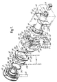
- FIG. 1 The construction of operating mechanism illustrated in Figure 1 includes a headrail 10 of conventional design in which is mounted (by means not shown) a housing 12 having a dismountable cover 14. Extending axially through the headrail 10 is a rotatable drive shaft 16 on which is engaged a rotatable member 18 having a suitable square cross-section aperture therethrough.
- the rotatable member 18 includes a reel 20 for a venetian blind lift tape 22 and an axially extending hub 24.
- a sleeve 26 mounted externally of the housing 12 with a square cross-section bore 28 engageable by the drive shaft 16, the sleeve having an external thread 30 along its length.
- this sleeve is provided with a step 31 which enables it to be connected to an identical sleeve if one wishes to extend the length of the sleeve.
- the sleeve is provided with a flange 32 carrying a radially projecting key 34.
- a nut 36 Threaded onto the external thread 30 is a nut 36 including an internally threaded bearing journal 38 which threadably engages the external thread 30.
- the nut 36 includes a radial wall 40 of generally rectangular shape provided with edge surfaces 42 for engagement with the inner wall of a headrail 10 and on its inner face (on the left of Figure 1) is a first abutment member element 44 in the form of a projection.
- a housing end wall 46 is shown at the right side of the housing 12, and includes a cut-out 48 of generally rectangular shape having a semi-circular bottom. On the outside of this housing end wall 46 is formed a guide 50 having two facing tracks 52. As can be seen, in the cut-out portion in Figure 1, the very end of the sleeve 26 is formed with a peripheral groove 54 engageable with the tracks 52 to prevent this sleeve from moving axially.
- a retractable stop member 56 having, on its outer surface, a cam follower projection 58 for a reason to be described below.
- an inwardly directed stop 60 which passes through a slot 62 in the end wall 46.
- a spring 64 which is of generally L-shape and includes a first arm 66 and a second arm 68 is arranged to engage the lower surface of the cam follower projection to urge the stop member upwardly.
- the upper end of the second arm 68 is provided with an inverted V-shaped end portion 70 which can be pushed into a pocket 72 formed on the exterior of the end wall 46. When the spring has been pushed upwardly into this pocket the resilience of the inverted U-shaped portion will effectively prevent downward movement of the spring 64.
- a cam member 74 having a peripheral cam surface 76.
- the cam member includes an outer journal sleeve 78 which engages over the internally threaded bearing journal 38 on the nut 36.
- a flat spring 80 which extends substantially along a chord of the cam member and engages a chordal flat surface 82 on the outer surface of the bearing journal 38 of the nut.
- An annular rib 83 engages in a groove in the nut to hold the cam member on the nut as a snap fit.
- the spring 80 provides a preferred orientation of the cam member with respect to the nut by engagement with the flat surface 82. However, relative rotation is still possible.
- an abutment 84 which extends generally radially and, in the construction illustrated, is in the form of a recess in the front face (that is to say the left face as seen in Figure 1) of the cam member.
- the recess is also partly delimited by an arcuate resilient finger 86 which is cantilevered from its right end, as seen in Figure 1, and is provided with a stepped free end 88.
- the outer surface of the cam member is provided with a second abutment member 90 which can engage with the first abutment member 44 on the nut 36.
- a tilt element 92 mounted on the rotatable member 18 is a tilt element 92 on which are supported the ladder cords 94 of the venetian blind, these ladder cords may have extended therebetween rungs 96, for carrying slats 98 (see Figures 4 and 5).
- These Figures also illustrate the bottom rail 100 which is supported by the lift tape 22 wound on the reel 20.
- the tilt element 92 is formed with a peripheral wall 102 having an arcuate opening 104 formed therein. Radially outwardly of this opening is a holding wall 106 including a central notch 108 into which are engaged means for locking the ladder cords 94.
- An axially extending bearing in the form of a sleeve 110 is formed on the interior of the annular tilt element and this engages on the axially extending hub 24 of the rotatable member 18 to allow the tilt element to pivot relative thereto.
- a coil clutch spring 114 Positioned within the peripheral wall 102 is a coil clutch spring 114 having two free ends 116 projecting generally radially, the free ends being accommodated within the opening 104 with significant clearance on either side.
- the spring 114 is sprung open somewhat and overlies a clutch sleeve 112 on the rotatable member 18 which is mounted coaxially with the hub 24 thereof. When the spring 114 is engaged on the clutch sleeve 112 it will cause the tilt element 92 to rotate with the rotatable member 18.
- a clutch actuating member 118 Mounted within the housing adjacent the tilt element 92 is a clutch actuating member 118 of generally annular shape.
- the clutch actuating member is provided with three circumferentially spaced arresting surfaces formed by first and second outer detents 120, 122 and an intermediate detent 124, these detents being positioned to be engageable by the stop 60 mounted on the retractable stop member 56. Facing generally to the left, as seen in Figure 1, the clutch actuating member 118 is provided with a finger 128 positioned to engage one or the other of the spring ends 116.
- the length of the sleeve 30 is chosen so that, as the blind nears its lowermost position, so the nut will reach an axial position so that the front face of the cam member 74 will just be approaching the key 34.
- the key will engage in the abutment 84 and will cause the cam member to rotate with it.
- the cam surface 76 is so shaped that the cam follower 58 will be forced downwardly against the action of the spring 64 and the stop 60 will temporarily disengage from the intermediate detent 124.
- the cam member will then have rotated to a position in which the cam no longer presses down on the cam follower 58 so that the stop member 56 will rise and the stop 60 will engage the outer detent 122.
- the finger 128 will then bear against the right hand spring end 116 thereby opening the spring and causing the clutch to slip.
- Further rotation of the drive shaft will eventually come to a halt when the second abutment member 90 on the cam member engages the first abutment member 44 on the nut from an opposite side. In this manner it can be prevented that the lift tape 22 will be unreeled to an extent that it starts rewinding in the wrong rotational sense.
- the stop member will then be engaged against the intermediate detent 124 so that the blind will be raised or lowered in an intermediate position as, for example, illustrated in Figure 4.
- the clutch actuating member 118 will rotate with the sleeve. If the operating handle or motor is then reversed, the drive shaft 16 will cause rotation in a clockwise direction.
- the key 34 will engage the stepped end portion 88 of the finger 86 and cause the cam to rotate back thereby depressing the cam follower 58 and allowing the stop to ride over the intermediate detent 124 as the actuating member 118 rotates in a clockwise direction.
- one or more of the breakout portions 126 can be snapped out, thereby to give a longer arcuate path before the stop touches one or more of the detents 120, 122, 124.
- housing used herein is to be read to cover not only a structure as illustrated, but also any form of frame, wall(s), support(s), locatable in, or forming part of, the blind headrail. Any such “housing” needs to be able to support the various components of the mechanism, such as the stop, clutch actuating member and cam member relative to one another.
- radially projecting key is to be read to cover any element capable of operating the cam member at the end of travel of the translating member.
- the translating member could include an internal peripheral groove housing a ball which could run in a helical groove on the exterior of the sleeve to cause the member to be translated along the sleeve and when the ball reaches the end of the groove it would be stopped and then caused to rotate the cam member.
- the ball forms the key.
Landscapes
- Engineering & Computer Science (AREA)
- Structural Engineering (AREA)
- Architecture (AREA)
- Civil Engineering (AREA)
- Blinds (AREA)
Claims (12)
- Mécanisme de manoeuvre pour les lamelles d'un store vénitien, ledit mécanisme comportant un logement (12) destiné à recevoir un arbre d'entraînement (16) pouvant tourner autour de son axe et adapté de manière à traverser ledit logement, un élément rotatif (18) monté dans ledit logement destiné à être animé d'un mouvement de rotation par ledit arbre d'entraînement dans l'une ou l'autre de deux directions opposées, un élément pivotant de basculement (92) en contact amovible avec ledit élément rotatif (18), cet élément de basculement étant destiné à supporter les lamelles et à basculer les lamelles ainsi supportées entre des positions extrêmes opposées, un mécanisme d'embrayage (112, 114) interposé entre ledit élément rotatif et ledit élément de basculement, des moyens (118) d'actionnement d'embrayage afin de désengager ledit mécanisme d'embrayage dans chacune desdites positions extrêmes opposées et des moyens suspension de mouvement espacés en rotation (120, 122, 124) associés audit moyen d'actionnement de l'embrayage déterminant les limites du basculement,
caractérisé par un organe d'arrêt rétractable (56) pouvant venir en contact avec au moins l'un desdits moyens de suspension de mouvement dans une position de basculement intermédiaire entre lesdites positions extrêmes opposées, d'où il résulte que, lorsque ledit organe d'arrêt est en contact avec ledit au moins un moyen de suspension de mouvement, le mécanisme d'embrayage est désengagé et la rotation dudit élément rotatif ne provoque pas la poursuite de la rotation dudit élément de basculement au-delà de ladite position intermédiaire, un manchon (26) destiné à entourer ledit arbre d'entraînement et pouvant tourner avec lui, ledit manchon s'étendant axialement vers l'extérieur dudit moyen (118) d'actionnement de l'embrayage, un ergot en saillie radiale (34) associé audit manchon dans le voisinage dudit moyen d'actionnement de l'embrayage, un filetage externe (30) formé sur ledit manchon, un élément de translation (36) entraîné par ledit filetage externe, d'où il résulte que, lorsque le manchon est animé d'un mouvement de rotation, l'élément de translation est amené à se déplacer dans le sens axial du manchon, un élément de came (74) entre ledit élément de translation et ledit logement pour rotation par rapport à eux, une surface à came (76) sur ledit élément de came, une butée (84) formée sur une surface extrême dudit élément de came en regard dudit ergot en saillie radiale, ladite butée (84) étant en contact avec ledit ergot (34) alors que l'élément de translation se déplace axialement jusqu'à une position d'extrémité sur ledit manchon après un nombre prédéterminé de tours dans cette direction particulière, à la suite de quoi, ledit ergot fait tourner ledit élément de came (74) qui agit alors au moins temporairement pour retirer l'organe d'arrêt (56) dudit au moins un moyen de suspension de mouvement (120, 122, 124) et par conséquent permet l'engagement du mécanisme d'embrayage (112, 114) et donc la rotation de l'élément de basculement (92) à partir de ladite position intermédiaire jusqu'à l'une desdites positions extrêmes opposées. - Mécanisme selon la revendication 1, caractérisé en ce que ledit manchon (26) est monté à l'extérieur dudit logement et/ou ledit manchon est retenu axialement par le logement au moyen d'une rainure circonférentielle (54) ménagée à un endroit proche d'une extrémité du manchon, ladite rainure étant en contact avec une partie (52) du logement.
- Mécanisme selon la revendication 1 ou 2, caractérisé en ce que ledit élément de translation (36) se présente sous la forme d'un écrou vissé sur ledit filetage externe (30) du manchon et en ce que l'écrou comporte une surface de bord (42) destinée à coulisser le long d'une surface intérieure d'un rail de tête (10) du store vénitien dans lequel le mécanisme est monté, afin d'empêcher la rotation dudit écrou.
- Mécanisme selon la revendication 3, caractérisé en ce que ledit écrou comprend un tourillon (38) pour l'élément de came (74), ledit tourillon comportant une surface plate (82) se rapportant à la corde, et en ce qu'un élément de ressort plat (80) est monté dans l'élément de came et est en contact avec ladite surface plate (82), la surface plate fournissant une orientation initiale préférée de l'élément de came par rapport audit écrou.
- Mécanisme selon la revendication 3 ou 4, caractérisé en ce que ledit écrou comporte un premier élément d'arrêt (44) coopérant avec un second élément d'arrêt (90) sur l'élément de came afin de limiter la rotation de ce dernier dans les deux directions.
- Mécanisme selon l'une quelconque des revendications précédentes, caractérisé en ce que ledit élément de came (74) comporte un cliquet pouvant dévier élastiquement (86) qui s'étend en étant contigu à ladite butée, ledit cliquet pouvant être surmonté par ledit ergot en saillie radiale (34) lors de la déviation dans un sens et venant en contact avec ledit ergot en saillie radiale lors du mouvement de retour de l'ergot, afin de ramener l'élément de came à sa position initiale.
- Mécanisme selon l'une quelconque des revendications précédentes, caractérisé en ce que ledit organe d'arrêt rétractable (56) est maintenu en coulissement sur ledit logement et est sollicité élastiquement vers la venue en contact avec les moyens de suspension de mouvement (120, 122, 124).
- Mécanisme selon l'une quelconque des revendications précédentes, caractérisé en ce que ledit moyen (118) d'actionnement de l'embrayage comprend un élément rotatif d'actionnement d'embrayage monté coaxialement avec l'arbre et a associé avec lui trois surfaces d'engagement espacées les unes des autres en rotation (120, 122, 124), les deux surfaces d'engagement extérieures (120, 122) déterminant lesdites positions extrêmes opposées lors de la venue en contact avec ledit d'arrêt rétractable et en ce que la surface d'engagement centrale (124) sur ledit élément d'actionnement d'embrayage forme une butée pour la position de basculement intermédiaire.
- Mécanisme selon la revendication 8, caractérisé en ce que ledit élément (118) d'actionnement d'embrayage comporte des portions (126) qui peuvent être détachées pour fournir des variantes d'emplacement pour lesdites surfaces d'engagement afin de présélectionner une valeur différente pour le basculement des lamelles.
- Mécanisme selon la revendication 8 ou 9, caractérisé en ce que ledit élément rotatif (18) comprend un moyeu s'étendant axialement (24) sur lequel est monté ledit élément de basculement (92), et un manchon d'embrayage (112) associé audit moyeu, en ce que ledit mécanisme d'embrayage comprend un ressort enroulé hélicoïdalement (114) reçu par ledit élément de basculement, ce ressort entourant ledit manchon d'embrayage s'étendant axialement et comportant des extrémités de ressort s'étendant radialement (116), et en ce que ledit élément (118) d'actionnement d'embrayage comprend un doigt s'étendant axialement (128) qui s'étend entre lesdites extrémités du ressort, l'agencement étant tel que l'engagement de l'une des extrémités radiales du ressort avec ledit doigt axial se traduit par l'ouverture desdites spires du ressort et par le désengagement dudit manchon et donc par le désengagement dudit mécanisme d'embrayage, lorsque l'élément d'actionnement est stoppé par l'un de ses cliquets contre l'organe d'arrêt rétractable.
- Mécanisme selon la revendication 10, caractérisé en ce que ledit élément de basculement (92) comprend un élément d'anneau ayant le même axe que ledit ressort enroulé hélicoïdalement et comporte un évidement circonférentiel (104) recevant les deux extrémités (116) du ressort s'étendant axialement ainsi que ledit doigt s'étendant axialement (128) placé entre elles.
- Mécanisme selon l'une quelconque des revendications précédentes, caractérisé en ce que ledit élément rotatif comprend une bobine (20) de bande afin d'enrouler la bande de levée pour l'élévation et l'abaissement du rail inférieur d'un store.
Priority Applications (4)
| Application Number | Priority Date | Filing Date | Title |
|---|---|---|---|
| AT88308108T ATE76674T1 (de) | 1988-09-01 | 1988-09-01 | Jalousieaufzieh- und wendemechanismus. |
| DE8888308108T DE3871526D1 (de) | 1988-09-01 | 1988-09-01 | Jalousieaufzieh- und wendemechanismus. |
| EP88308108A EP0356590B1 (fr) | 1988-09-01 | 1988-09-01 | Mécanisme de levage et d'inclinaison pour store vénitien |
| AU40877/89A AU616046B2 (en) | 1988-09-01 | 1989-08-29 | Venetian blind lifting and tilting mechanism |
Applications Claiming Priority (1)
| Application Number | Priority Date | Filing Date | Title |
|---|---|---|---|
| EP88308108A EP0356590B1 (fr) | 1988-09-01 | 1988-09-01 | Mécanisme de levage et d'inclinaison pour store vénitien |
Publications (2)
| Publication Number | Publication Date |
|---|---|
| EP0356590A1 EP0356590A1 (fr) | 1990-03-07 |
| EP0356590B1 true EP0356590B1 (fr) | 1992-05-27 |
Family
ID=8200192
Family Applications (1)
| Application Number | Title | Priority Date | Filing Date |
|---|---|---|---|
| EP88308108A Expired EP0356590B1 (fr) | 1988-09-01 | 1988-09-01 | Mécanisme de levage et d'inclinaison pour store vénitien |
Country Status (4)
| Country | Link |
|---|---|
| EP (1) | EP0356590B1 (fr) |
| AT (1) | ATE76674T1 (fr) |
| AU (1) | AU616046B2 (fr) |
| DE (1) | DE3871526D1 (fr) |
Cited By (1)
| Publication number | Priority date | Publication date | Assignee | Title |
|---|---|---|---|---|
| CN104254660A (zh) * | 2012-02-27 | 2014-12-31 | 亨特道格拉斯工业公司 | 百叶窗倾斜总成和控制倾斜梯格的方法 |
Families Citing this family (6)
| Publication number | Priority date | Publication date | Assignee | Title |
|---|---|---|---|---|
| EP0600133A1 (fr) * | 1992-12-04 | 1994-06-08 | Nien Made Enterprise Co., Ltd. | Dispositif d'inclinaison |
| US5553649A (en) * | 1993-07-05 | 1996-09-10 | Kabushiki Kaisha Nichibei | Blind apparatus |
| CH700450A1 (de) * | 2009-02-27 | 2010-08-31 | Griesser Holding Ag | Wendelager für Storen mit Lamellenelementen. |
| CN102808573B (zh) * | 2012-07-30 | 2013-08-28 | 杭州欧卡索拉科技有限公司 | 用于百叶窗的升降翻转器 |
| CN102808577B (zh) * | 2012-07-30 | 2013-08-28 | 杭州欧卡索拉科技有限公司 | 百叶窗的卷轮机构及带齿轮离合器翻转机构的卷轮系统 |
| CN103306594B (zh) * | 2013-07-03 | 2016-04-20 | 立森(博罗)木器有限公司 | 一种隐形拉绳窗帘 |
Family Cites Families (4)
| Publication number | Priority date | Publication date | Assignee | Title |
|---|---|---|---|---|
| CH608563A5 (fr) * | 1976-04-30 | 1979-01-15 | Schenker Emil Storen Und Masch | |
| SE8203812L (sv) * | 1982-06-18 | 1983-12-19 | Perma System Ab | Lagerbock for fasadpersienner |
| DE3625365A1 (de) * | 1986-07-26 | 1988-02-04 | Warema Renkhoff Gmbh & Co Kg | Wendevorrichtung fuer eine raffbare lamellenjalousie mit drei lamellenstellungen |
| CA1293181C (fr) * | 1988-02-29 | 1991-12-17 | Norbert Marocco | Organe de commande-regulation pour store venitien |
-
1988
- 1988-09-01 EP EP88308108A patent/EP0356590B1/fr not_active Expired
- 1988-09-01 AT AT88308108T patent/ATE76674T1/de not_active IP Right Cessation
- 1988-09-01 DE DE8888308108T patent/DE3871526D1/de not_active Expired - Fee Related
-
1989
- 1989-08-29 AU AU40877/89A patent/AU616046B2/en not_active Ceased
Cited By (2)
| Publication number | Priority date | Publication date | Assignee | Title |
|---|---|---|---|---|
| CN104254660A (zh) * | 2012-02-27 | 2014-12-31 | 亨特道格拉斯工业公司 | 百叶窗倾斜总成和控制倾斜梯格的方法 |
| CN104254660B (zh) * | 2012-02-27 | 2016-08-24 | 亨特道格拉斯工业公司 | 百叶窗倾斜总成和控制倾斜梯格的方法 |
Also Published As
| Publication number | Publication date |
|---|---|
| EP0356590A1 (fr) | 1990-03-07 |
| ATE76674T1 (de) | 1992-06-15 |
| AU4087789A (en) | 1990-03-08 |
| AU616046B2 (en) | 1991-10-17 |
| DE3871526D1 (de) | 1992-07-02 |
Similar Documents
| Publication | Publication Date | Title |
|---|---|---|
| CA2291314C (fr) | Capuchon d'extremite et support combines | |
| US6851291B2 (en) | Motorized locking mechanism | |
| EP1435426B1 (fr) | Dispositif de renversement pour un store à lamelles | |
| US20200018116A1 (en) | Window shade and actuating system thereof | |
| EP0356590B1 (fr) | Mécanisme de levage et d'inclinaison pour store vénitien | |
| JP3965151B2 (ja) | 日射遮蔽装置の障害物検知停止装置 | |
| EP1052365B1 (fr) | Dispositif d'entraînement pour un store vénitien | |
| EP2593627B1 (fr) | Système de commande pour couvertures d'ouvertures architecturales ayant un entraînement réversible et un seul élément de man uvre | |
| JP2004027841A (ja) | シャッタ等の巻取り装置 | |
| JP2695553B2 (ja) | ブラインドの昇降回転機構 | |
| JP2656430B2 (ja) | 電動ブラインドの昇降回転機構 | |
| JPH042315Y2 (fr) | ||
| JP2514189Y2 (ja) | 電動式シャッタ―の開閉装置 | |
| CN223165530U (zh) | 一种升降器及灯具 | |
| JPH0633672A (ja) | 電動ブラインド用昇降ユニットのクラッチ機構 | |
| JP2008110639A (ja) | スライドドア | |
| JP2000131765A5 (fr) | ||
| JP4909769B2 (ja) | ブラインド用昇降回転装置 | |
| JPH0347094Y2 (fr) | ||
| JPH0720316Y2 (ja) | 電動横型ブラインドの上限リミット装置 | |
| JPH0756479Y2 (ja) | 巻取式シャッタ装置 | |
| JPH0432473Y2 (fr) | ||
| JPH02276078A (ja) | テープカセット | |
| JP2002004750A (ja) | 横型ブラインドのボトムレール下限位置調整装置 | |
| JPH0540235Y2 (fr) |
Legal Events
| Date | Code | Title | Description |
|---|---|---|---|
| PUAI | Public reference made under article 153(3) epc to a published international application that has entered the european phase |
Free format text: ORIGINAL CODE: 0009012 |
|
| AK | Designated contracting states |
Kind code of ref document: A1 Designated state(s): AT BE CH DE ES FR GB GR IT LI LU NL SE |
|
| RBV | Designated contracting states (corrected) |
Designated state(s): AT CH DE ES FR GB IT LI NL SE |
|
| 17P | Request for examination filed |
Effective date: 19900504 |
|
| 17Q | First examination report despatched |
Effective date: 19910603 |
|
| RAP1 | Party data changed (applicant data changed or rights of an application transferred) |
Owner name: HUNTER DOUGLAS INDUSTRIES B.V. |
|
| GRAA | (expected) grant |
Free format text: ORIGINAL CODE: 0009210 |
|
| AK | Designated contracting states |
Kind code of ref document: B1 Designated state(s): AT CH DE ES FR GB IT LI NL SE |
|
| PG25 | Lapsed in a contracting state [announced via postgrant information from national office to epo] |
Ref country code: IT Free format text: LAPSE BECAUSE OF FAILURE TO SUBMIT A TRANSLATION OF THE DESCRIPTION OR TO PAY THE FEE WITHIN THE PRESCRIBED TIME-LIMIT;WARNING: LAPSES OF ITALIAN PATENTS WITH EFFECTIVE DATE BEFORE 2007 MAY HAVE OCCURRED AT ANY TIME BEFORE 2007. THE CORRECT EFFECTIVE DATE MAY BE DIFFERENT FROM THE ONE RECORDED. Effective date: 19920527 Ref country code: NL Effective date: 19920527 Ref country code: LI Effective date: 19920527 Ref country code: FR Effective date: 19920527 Ref country code: ES Free format text: THE PATENT HAS BEEN ANNULLED BY A DECISION OF A NATIONAL AUTHORITY Effective date: 19920527 Ref country code: CH Effective date: 19920527 Ref country code: SE Effective date: 19920527 Ref country code: AT Effective date: 19920527 |
|
| REF | Corresponds to: |
Ref document number: 76674 Country of ref document: AT Date of ref document: 19920615 Kind code of ref document: T |
|
| REF | Corresponds to: |
Ref document number: 3871526 Country of ref document: DE Date of ref document: 19920702 |
|
| REG | Reference to a national code |
Ref country code: CH Ref legal event code: PL |
|
| PG25 | Lapsed in a contracting state [announced via postgrant information from national office to epo] |
Ref country code: GB Effective date: 19920901 |
|
| PGFP | Annual fee paid to national office [announced via postgrant information from national office to epo] |
Ref country code: DE Payment date: 19920923 Year of fee payment: 5 |
|
| EN | Fr: translation not filed | ||
| NLV1 | Nl: lapsed or annulled due to failure to fulfill the requirements of art. 29p and 29m of the patents act | ||
| PLBE | No opposition filed within time limit |
Free format text: ORIGINAL CODE: 0009261 |
|
| STAA | Information on the status of an ep patent application or granted ep patent |
Free format text: STATUS: NO OPPOSITION FILED WITHIN TIME LIMIT |
|
| GBPC | Gb: european patent ceased through non-payment of renewal fee |
Effective date: 19920901 |
|
| 26N | No opposition filed | ||
| PG25 | Lapsed in a contracting state [announced via postgrant information from national office to epo] |
Ref country code: DE Effective date: 19940601 |