EP0356591B1 - Ultraschall-Antriebsvorrichtung - Google Patents
Ultraschall-Antriebsvorrichtung Download PDFInfo
- Publication number
- EP0356591B1 EP0356591B1 EP88308166A EP88308166A EP0356591B1 EP 0356591 B1 EP0356591 B1 EP 0356591B1 EP 88308166 A EP88308166 A EP 88308166A EP 88308166 A EP88308166 A EP 88308166A EP 0356591 B1 EP0356591 B1 EP 0356591B1
- Authority
- EP
- European Patent Office
- Prior art keywords
- driving device
- stator
- balls
- ultrasonic driving
- bolt
- Prior art date
- Legal status (The legal status is an assumption and is not a legal conclusion. Google has not performed a legal analysis and makes no representation as to the accuracy of the status listed.)
- Expired - Lifetime
Links
- 230000000750 progressive effect Effects 0.000 claims description 12
- 239000002184 metal Substances 0.000 claims description 10
- 239000000919 ceramic Substances 0.000 claims description 6
- 239000000463 material Substances 0.000 claims description 6
- 239000010687 lubricating oil Substances 0.000 claims description 3
- 230000003247 decreasing effect Effects 0.000 description 3
- 230000010363 phase shift Effects 0.000 description 2
- 150000001875 compounds Chemical class 0.000 description 1
- 230000000694 effects Effects 0.000 description 1
- 239000000203 mixture Substances 0.000 description 1
Images


Classifications
-
- H—ELECTRICITY
- H02—GENERATION; CONVERSION OR DISTRIBUTION OF ELECTRIC POWER
- H02N—ELECTRIC MACHINES NOT OTHERWISE PROVIDED FOR
- H02N2/00—Electric machines in general using piezoelectric effect, electrostriction or magnetostriction
- H02N2/10—Electric machines in general using piezoelectric effect, electrostriction or magnetostriction producing rotary motion, e.g. rotary motors
- H02N2/16—Electric machines in general using piezoelectric effect, electrostriction or magnetostriction producing rotary motion, e.g. rotary motors using travelling waves, i.e. Rayleigh surface waves
- H02N2/163—Motors with ring stator
-
- H—ELECTRICITY
- H02—GENERATION; CONVERSION OR DISTRIBUTION OF ELECTRIC POWER
- H02N—ELECTRIC MACHINES NOT OTHERWISE PROVIDED FOR
- H02N2/00—Electric machines in general using piezoelectric effect, electrostriction or magnetostriction
- H02N2/0005—Electric machines in general using piezoelectric effect, electrostriction or magnetostriction producing non-specific motion; Details common to machines covered by H02N2/02 - H02N2/16
- H02N2/001—Driving devices, e.g. vibrators
- H02N2/0045—Driving devices, e.g. vibrators using longitudinal or radial modes combined with torsion or shear modes
-
- H—ELECTRICITY
- H02—GENERATION; CONVERSION OR DISTRIBUTION OF ELECTRIC POWER
- H02N—ELECTRIC MACHINES NOT OTHERWISE PROVIDED FOR
- H02N2/00—Electric machines in general using piezoelectric effect, electrostriction or magnetostriction
- H02N2/10—Electric machines in general using piezoelectric effect, electrostriction or magnetostriction producing rotary motion, e.g. rotary motors
- H02N2/106—Langevin motors
-
- H—ELECTRICITY
- H02—GENERATION; CONVERSION OR DISTRIBUTION OF ELECTRIC POWER
- H02N—ELECTRIC MACHINES NOT OTHERWISE PROVIDED FOR
- H02N2/00—Electric machines in general using piezoelectric effect, electrostriction or magnetostriction
- H02N2/10—Electric machines in general using piezoelectric effect, electrostriction or magnetostriction producing rotary motion, e.g. rotary motors
- H02N2/12—Constructional details
- H02N2/123—Mechanical transmission means, e.g. for gearing
Definitions
- the present invention relates to ultrasonic driving devices having structures for decreasing wear.
- two groups of electrodes are attached to one end of a ring-type piezoelectric ceramic, the two groups of electrodes being so positioned that standing waves respectively generated by the two groups of electrodes are shifted every ⁇ /2 in each position.
- the parts of the ring-type piezoelectric vibrator corresponding to the electrodes are alternately polarised in reverse.
- the two groups of electrodes are respectively connected to two oscillators for respectively generating alternating current voltages have ⁇ /2 phase shift with respect to each other.
- US-A-4752711 discloses an ultrasonic driving device, acknowledged in the pre-characterising portion of the present independent claim, in which the rotary member and the piezoelectric vibrator contact each other through a plurality of contact points. Although there is a disclosure that some wear can be reduced, by forming the contact points as balls rotatably attached to the rotary member, the attachment is deliberately such that the rotation of the balls is substantially prevented. Moreover, although there is a general disclosure of the need for the rotary member to be pressed towards the piezoelectric vibrator, there is no disclosure of how that application of pressure can be achieved without additional wear.
- the primary object of the present invention to provide an ultrasonic driving device having a structure for enabling wear to be further reduced.
- an ultrasonic driving device comprises: a stator including piezoelectric vibrator means, a plurality of balls, discs or rolls held in contact with the stator by a pressure member acted upon by pressure means, and rotary means rotatably attached to the plurality of balls, discs or rolls, whereby driving the piezoelectric vibrator means causes the stator to generate a progressive wave which is transmitted through the plurality of balls, discs or rolls to drive the rotary means; characterised in that the plurality of balls, discs or rolls extend through the rotary means into contact with the pressure member and roll along the pressure member when the rotary means is driven by the progressive wave.
- ring-type piezoelectric vibrators 13 of piezoelectric ceramics are put between a short metal block 15 and a long metal block 14 and male screws 16a and 16b at respective ends of a bolt 16 are engaged with female screws in the metal blocks 14 and 15, whereby a stator 17 is constituted.
- a rotary member 18 is strongly contacted with the end of the stator 17 by a spring.
- the rotary member 18 is strongly pressed to the stator 17 by the spring for transmitting the ellipse vibration generated on the end of the stator 17 to the rotary member 18. Therefore, the contact faces between the end of the stator 17 and the rotary member 18 wear against each other. Thus, a lining material is put between the end of the stator 17 and the rotary member 18 for decreasing the wear between the end of the stator 17 and the rotary member 18. However, even so, the lining material is worn out, noise is generated at the contact between the end of the stator 17 and the rotary member 18 and the life of the ultrasonic driving device is short.
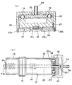
- a plurality of balls 19 are rotatably supported in a rotary member 20 and the balls are contacted with the end of the stator 17.
- One end of a bolt 22 is engaged with a screw at the end of the stator 17 and the other end of the bolt 22 is passed through centre holes in the rotary member 20, a pressure member 21 and a spring washer 23 and, then, a nut 24 is engaged with the screw at the other end of the bolt 22. Therefore, the balls 19 are pressed against the end of the stator 17 by the pressure member 21.
- the lubricating oil influences the rotation of the balls 19 for the good, because the balls 19 still roll on the surface 21a of the pressure member 21 with point contact, but glide on the end of the stator 17. Wear of the balls 19, the end of the stator 17 and the pressure member 21 is decreased. Therefore, the life of the ultrasonic driving device according to the present invention becomes long.
- FIGs. 5 and 6 there is shown a stator 17, a rotary member 20, a pressure member 21, a bolt 22, a washer 23 and a nut 24. These components are the same as those in Fig. 2. However, a plurality of disks 25 or rolls are rotatably supported with the rotary member 20 in a circle instead of the balls 19.
- the ultrasonic driving device of this embodiment is driven the same as the above embodiment and has the same effect.
- electrodes 26a and 26b are formed on the ends of a ring-type ceramic piezoelectric vibrator 26.
- a member 27 for transmitting vibration and a member 28 for not transmitting vibration are closely attached with the same thickness on the electrode 26a of the piezoelectric vibrator 26.
- a bolt 29 is passed through holes at the portion between the members 27 and 28, the piezoelectric vibrator 26 and the electrodes 26a and 26b and holes in a rotary member 20 supporting balls 19 and a pressure member 21. Screws at the ends of the bolt 29 are engaged with nuts 30a and 30b and these elements are fixed.
- the ultrasonic driving device having this ring-type piezoelectric vibrator 26 is provided by the present applicant (Japanese Patent Application 48515/1987).
- Japanese Patent Application 48515/1987 When alternating current voltage is applied to the electrodes 26a and 26b in the ultrasonic driving device, a progressive wave is generated from its circumferential edge to its central edge on both sides of the piezoelectric vibrator 26. Therefore, the balls 19 are rotated according to the progressive wave transmitted through the member 27 and thus the rotary member 20 is rotated with the balls 19.
- rolls and disks can be used instead of the balls.
- a resilient member 27 and a piezoelectric vibrator 26 are provided.
- a plurality of balls 19 supported with a rotary member 20 are contacted with the resilient member 27.
- a rotary shaft 28 of the rotary member 20 is protruded beyond a bearing 30 of a case 29.
- a screw 31 is engaged with a screw in the resilient member 27 through holes in a bottom plate 29a and a washer 31a, and the bottom plate 29a is fixed with the case 29 by screws 29b. Therefore, the balls 19 are strongly contacted with the inside of the case 29 and the surface of the resilient member 27 by the rotation of the screw 31.
- the balls 19 are rotated by the progressive wave and the rotary member 20 is rotated so that a rotary force is obtained from the rotary shaft 28, and again rolls and disks can be used instead of the balls.
- a stator 17 comprises a short metal block 14, a long metal block 15 and a bolt 16 and is the same as the stator 17 in Fig. 1.
- a hole 32 is formed through the metal blocks 14 and 15 and the bolt 16, and a bolt 33 is passed through the hole 32.
- One end of the bolt 33 is engaged with a nut 34b through a spring washer 34c and the other end of the bolt 33 is passed through a bearing 20a supported with a rotary member 20 and a hole in a pressure member 21, and is engaged with a nut 34a.
- Balls 19 rotatably supported with the rotary member 20 are pressed between the end of the stator 17 and the pressure member 21. Both ends of an arm 37 having a rotary shaft 36 are fixed to the sides of the rotary member 20.
- this ultrasonic driving device when the balls 19 are rotated owing to the progressive wave generated on the end of the stator 17, the rotary member 20 is rotated and the rotary shaft 36 is rotated and, consequently, this ultrasonic driving device can be used instead of a known electric motor.
Landscapes
- General Electrical Machinery Utilizing Piezoelectricity, Electrostriction Or Magnetostriction (AREA)
Claims (9)
- Ultraschall-Antriebsvorrichtung, die aufweist: einen Stator (17) mit piezoelektrischen Schwingermitteln (13; 26), eine Vielzahl von Kugeln (19), Scheiben (25) oder Rollen, die durch ein durch Druckmittel (22 bis 24; 29 bis 30b; 29a bis 31; 33 bis 34c) betätigtes Druckteil (21; 29) in Kontakt mit dem Stator (17) gehalten werden, und ein Rotormittel (20), das drehbar an der Vielzahl von Kugeln (19), Scheiben (25) oder Rollen angebracht ist, wobei Antreiben der piezoelektrischen Schwingermittel (13; 26) bewirkt, daß der Stator (17) eine fortschreitende Welle erzeugt, die durch die Vielzahl von Kugeln (19), Scheiben (25) oder Rollen übertragen wird, um das Rotormittel (20) anzutreiben;
dadurch gekennzeichnet, daß die Vielzahl von Kugeln (19), Scheiben (25) oder Rollen sich durch das Rotormittel (20) hindurch in Kontakt mit dem Druckteil (21; 29) erstreckt und entlang des Druckteils (21; 29) rollt, wenn das Rotormittel (20) durch die fortschreitende Welle angetrieben ist. - Ultraschall-Antriebsvorrichtung gemäß Anspruch 1, dadurch gekennzeichnet, daß Schmieröl auf den Umfang der Kugeln, Scheiben oder Rollen aufgebracht ist.
- Ultraschall-Antriebsvorrichtung gemäß Anspruch 1 oder Anspruch 2, dadurch gekennzeichnet, daß der Stator einen keramischen piezoelektrischen Schwinger oder keramische piezoelektrische Schwinger (13), zwei Metallblöcke (14, 15) und einen Bolzen (16) aufweist.
- Ultraschall-Antriebsvorrichtung gemäß Anspruch 3, dadurch gekennzeichnet, daß das Druckmittel ein Bolzen (22) ist, dessen eines Ende mit dem Stator durch Schraubenmittel verbunden ist und dessen anderes Ende durch eine Mutter (24) befestigt ist.
- Ultraschall-Antriebsvorrichtung gemäß Anspruch 3, dadurch gekennzeichnet, daß das Druckmittel ein Bolzen (33) ist, der durch Löcher in dem Bolzen des Stators, dem Rotormittel und dem Druckteil führt, wobei Schrauben an beiden Enden des Bolzens durch Muttern (34a, 34b) befestigt sind, und das Rotormittel (20) durch einen Arm (37) an einem Rotorschaft (36) befestigt ist.
- Ultraschall-Antriebsvorrichtung gemäß Anspruch 1 oder Anspruch 2, dadurch gekennzeichnet, daß der Stator einen ringartigen keramischen piezoelektrischen Schwinger (26) und Elektroden (26a, 26b) auf seinen beiden Seiten aufweist.
- Ultraschall-Antriebsvorrichtung gemäß Anspruch 6, dadurch gekennzeichnet, daß der Stator schwingungsübertragendes Material (27) und ein schwingungsisolierendes Material (28) aufweist, die eng anliegend auf der Elektrode (26a) auf einer Seite des piezoelektrischen Schwingers befestigt sind, wobei die Kugeln, Scheiben oder Rollen in Kontakt mit dem schwingungsübertragenden Material und dem schwingungsisolierenden Material sind, und einen Bolzen (29), der durch die Löcher in dem Stator, dem Rotormittel und dem Druckteil führt, wobei Schrauben an beiden Enden des Bolzens durch Muttern (30a, 30b) befestigt sind.
- Ultraschall-Antriebsvorrichtung gemäß einem der Ansprüche 3 bis 7, dadurch gekennzeichnet, daß das Druckteil ein zylindrischer Block (21) ist.
- Ultraschall-Antriebsvorrichtung gemäß Anspruch 1 oder Anspruch 2, dadurch gekennzeichnet, daß das Druckteil ein Kasten (29) ist, mit einem Lager (30), durch das ein an dem Rotormittel (20) befestigter Rotorschaft (28) verläuft, wobei der Stator einen ringartigen keramischen piezoelektrischen Schwinger (26) und ein elastisches Teil (27) aufweist, die Vielzahl von Kugeln, Scheiben oder Rollen in Kontakt mit dem elastischen Teil ist und das Druckmittel eine Schraube (31) ist, die mit einer Bodenplatte (29a) des Kastens zum Pressen des elastischen Teils (27) in Eingriff ist.
Priority Applications (3)
| Application Number | Priority Date | Filing Date | Title |
|---|---|---|---|
| EP88308166A EP0356591B1 (de) | 1988-09-02 | 1988-09-02 | Ultraschall-Antriebsvorrichtung |
| DE3854692T DE3854692T2 (de) | 1988-09-02 | 1988-09-02 | Ultraschall-Antriebsvorrichtung. |
| US07/241,602 US4893046A (en) | 1988-09-02 | 1988-09-08 | Ultrasonic driving device |
Applications Claiming Priority (1)
| Application Number | Priority Date | Filing Date | Title |
|---|---|---|---|
| EP88308166A EP0356591B1 (de) | 1988-09-02 | 1988-09-02 | Ultraschall-Antriebsvorrichtung |
Publications (2)
| Publication Number | Publication Date |
|---|---|
| EP0356591A1 EP0356591A1 (de) | 1990-03-07 |
| EP0356591B1 true EP0356591B1 (de) | 1995-11-15 |
Family
ID=8200193
Family Applications (1)
| Application Number | Title | Priority Date | Filing Date |
|---|---|---|---|
| EP88308166A Expired - Lifetime EP0356591B1 (de) | 1988-09-02 | 1988-09-02 | Ultraschall-Antriebsvorrichtung |
Country Status (3)
| Country | Link |
|---|---|
| US (1) | US4893046A (de) |
| EP (1) | EP0356591B1 (de) |
| DE (1) | DE3854692T2 (de) |
Families Citing this family (9)
| Publication number | Priority date | Publication date | Assignee | Title |
|---|---|---|---|---|
| DE3920726A1 (de) * | 1988-06-29 | 1990-01-04 | Olympus Optical Co | Ultraschalloszillator |
| US5140215A (en) * | 1988-09-19 | 1992-08-18 | Brother Kogyo Kabushiki Kaisha | Vibrator and ultrasonic motor employing the same |
| US5032754A (en) * | 1989-03-31 | 1991-07-16 | Brother Kogyo Kabushiki Kaisha | Piezoelectric transducer for an ultrasonic motor |
| US5428260A (en) * | 1990-08-03 | 1995-06-27 | Canon Kabushiki Kaisha | Vibration driven motor |
| JP3205026B2 (ja) * | 1992-01-30 | 2001-09-04 | キヤノン株式会社 | 振動波駆動装置および振動波駆動装置を有する装置 |
| RU2061218C1 (ru) * | 1992-07-22 | 1996-05-27 | Всероссийский научно-исследовательский институт природных газов и газовых технологий | Устройство для определения свойств текучих сред |
| US6404104B1 (en) * | 1997-11-27 | 2002-06-11 | Canon Kabushiki Kaisha | Vibration type actuator and vibration type driving apparatus |
| JP4756916B2 (ja) * | 2005-05-31 | 2011-08-24 | キヤノン株式会社 | 振動波モータ |
| JP7672738B2 (ja) * | 2021-08-30 | 2025-05-08 | 国立大学法人埼玉大学 | 回転装置、モータ、及びポンプ |
Family Cites Families (3)
| Publication number | Priority date | Publication date | Assignee | Title |
|---|---|---|---|---|
| US4663556A (en) * | 1984-01-11 | 1987-05-05 | Hitachi Maxell, Ltd. | Torsional mode ultrasonic vibrator |
| US4634916A (en) * | 1984-10-02 | 1987-01-06 | Ngk Spark Plug Co., Ltd. | Piezoelectric rotary driver |
| US4752711A (en) * | 1985-03-29 | 1988-06-21 | Canon Kabushiki Kaisha | Vibration wave motor |
-
1988
- 1988-09-02 EP EP88308166A patent/EP0356591B1/de not_active Expired - Lifetime
- 1988-09-02 DE DE3854692T patent/DE3854692T2/de not_active Expired - Fee Related
- 1988-09-08 US US07/241,602 patent/US4893046A/en not_active Expired - Lifetime
Also Published As
| Publication number | Publication date |
|---|---|
| US4893046A (en) | 1990-01-09 |
| EP0356591A1 (de) | 1990-03-07 |
| DE3854692T2 (de) | 1996-04-18 |
| DE3854692D1 (de) | 1995-12-21 |
Similar Documents
| Publication | Publication Date | Title |
|---|---|---|
| EP0289734B1 (de) | Ultraschall-Antriebsanordnung | |
| EP0299415B1 (de) | Ultraschalltreiberanordnung | |
| EP0301430B1 (de) | Ultraschalltreiberanordnung | |
| US5723935A (en) | Vibration driven motor | |
| EP0359875B1 (de) | Ultraschallantriebsanordnungen | |
| US5101132A (en) | Linear ultrasonic motor | |
| US4933590A (en) | Ultrasonic motor | |
| JPH03190573A (ja) | 振動波モータ | |
| US4893046A (en) | Ultrasonic driving device | |
| EP0552754A1 (de) | Durch Vibrationen angetriebener Motor | |
| EP0301429B1 (de) | Ultraschalltreiberanordnung | |
| US6198201B1 (en) | Vibration wave apparatus | |
| CA1299228C (en) | Ultrasonic driving device | |
| JP3016577B2 (ja) | 振動波装置 | |
| JPH0744850B2 (ja) | 振動波モ−タ− | |
| JP2584999B2 (ja) | 超音波駆動装置 | |
| CA1301230C (en) | Ultrasonic driving device | |
| JP2684418B2 (ja) | 超音波アクチュエータ | |
| EP0312409A2 (de) | Ultraschallantriebsvorrichtung | |
| JP2620609B2 (ja) | 超音波駆動装置 | |
| JP2599954B2 (ja) | 超音波駆動装置 | |
| CA1298866C (en) | Ultrasonic driving device | |
| JPH0744856B2 (ja) | 超音波モータ | |
| JP2639551B2 (ja) | 超音波駆動装置 | |
| SU661661A1 (ru) | Пьезоэлектрический реверсивный двигатель |
Legal Events
| Date | Code | Title | Description |
|---|---|---|---|
| PUAI | Public reference made under article 153(3) epc to a published international application that has entered the european phase |
Free format text: ORIGINAL CODE: 0009012 |
|
| AK | Designated contracting states |
Kind code of ref document: A1 Designated state(s): CH DE FR GB IT LI NL SE |
|
| 17P | Request for examination filed |
Effective date: 19900824 |
|
| 17Q | First examination report despatched |
Effective date: 19930301 |
|
| GRAA | (expected) grant |
Free format text: ORIGINAL CODE: 0009210 |
|
| AK | Designated contracting states |
Kind code of ref document: B1 Designated state(s): CH DE FR GB IT LI NL SE |
|
| PG25 | Lapsed in a contracting state [announced via postgrant information from national office to epo] |
Ref country code: LI Effective date: 19951115 Ref country code: NL Free format text: LAPSE BECAUSE OF FAILURE TO SUBMIT A TRANSLATION OF THE DESCRIPTION OR TO PAY THE FEE WITHIN THE PRESCRIBED TIME-LIMIT Effective date: 19951115 Ref country code: CH Effective date: 19951115 Ref country code: IT Free format text: LAPSE BECAUSE OF FAILURE TO SUBMIT A TRANSLATION OF THE DESCRIPTION OR TO PAY THE FEE WITHIN THE PRE;WARNING: LAPSES OF ITALIAN PATENTS WITH EFFECTIVE DATE BEFORE 2007 MAY HAVE OCCURRED AT ANY TIME BEFORE 2007. THE CORRECT EFFECTIVE DATE MAY BE DIFFERENT FROM THE ONE RECORDED.SCRIBED TIME-LIMIT Effective date: 19951115 |
|
| REF | Corresponds to: |
Ref document number: 3854692 Country of ref document: DE Date of ref document: 19951221 |
|
| PG25 | Lapsed in a contracting state [announced via postgrant information from national office to epo] |
Ref country code: SE Effective date: 19960215 |
|
| ET | Fr: translation filed | ||
| NLV1 | Nl: lapsed or annulled due to failure to fulfill the requirements of art. 29p and 29m of the patents act | ||
| REG | Reference to a national code |
Ref country code: CH Ref legal event code: PL |
|
| PLBE | No opposition filed within time limit |
Free format text: ORIGINAL CODE: 0009261 |
|
| STAA | Information on the status of an ep patent application or granted ep patent |
Free format text: STATUS: NO OPPOSITION FILED WITHIN TIME LIMIT |
|
| 26N | No opposition filed | ||
| PGFP | Annual fee paid to national office [announced via postgrant information from national office to epo] |
Ref country code: FR Payment date: 19980909 Year of fee payment: 11 |
|
| PGFP | Annual fee paid to national office [announced via postgrant information from national office to epo] |
Ref country code: GB Payment date: 19991004 Year of fee payment: 12 |
|
| PG25 | Lapsed in a contracting state [announced via postgrant information from national office to epo] |
Ref country code: FR Free format text: LAPSE BECAUSE OF NON-PAYMENT OF DUE FEES Effective date: 20000531 |
|
| PGFP | Annual fee paid to national office [announced via postgrant information from national office to epo] |
Ref country code: DE Payment date: 20000614 Year of fee payment: 12 |
|
| REG | Reference to a national code |
Ref country code: FR Ref legal event code: ST |
|
| PG25 | Lapsed in a contracting state [announced via postgrant information from national office to epo] |
Ref country code: GB Free format text: LAPSE BECAUSE OF NON-PAYMENT OF DUE FEES Effective date: 20000902 |
|
| GBPC | Gb: european patent ceased through non-payment of renewal fee |
Effective date: 20000902 |
|
| PG25 | Lapsed in a contracting state [announced via postgrant information from national office to epo] |
Ref country code: DE Free format text: LAPSE BECAUSE OF NON-PAYMENT OF DUE FEES Effective date: 20010601 |