EP0356631A2 - Distributeur centrifuge d'engrais, notamment distributeur à grande couverture - Google Patents
Distributeur centrifuge d'engrais, notamment distributeur à grande couverture Download PDFInfo
- Publication number
- EP0356631A2 EP0356631A2 EP89110457A EP89110457A EP0356631A2 EP 0356631 A2 EP0356631 A2 EP 0356631A2 EP 89110457 A EP89110457 A EP 89110457A EP 89110457 A EP89110457 A EP 89110457A EP 0356631 A2 EP0356631 A2 EP 0356631A2
- Authority
- EP
- European Patent Office
- Prior art keywords
- centrifugal
- elements
- throwing
- centrifugal discs
- distributor
- Prior art date
- Legal status (The legal status is an assumption and is not a legal conclusion. Google has not performed a legal analysis and makes no representation as to the accuracy of the status listed.)
- Withdrawn
Links
Images
Classifications
-
- A—HUMAN NECESSITIES
- A01—AGRICULTURE; FORESTRY; ANIMAL HUSBANDRY; HUNTING; TRAPPING; FISHING
- A01C—PLANTING; SOWING; FERTILISING
- A01C17/00—Fertilisers or seeders with centrifugal wheels
Definitions
- the invention relates to a centrifugal fertilizer spreader, in particular large-area fertilizer spreader according to the preamble of patent claim 1.
- centrifugal fertilizer spreader is already known from DE-OS 33 13 892.
- This centrifugal fertilizer spreader is designed as a large area spreader and has an elongated storage container.
- a conveyor belt which closes the storage container downwards and which is simultaneously designed as a metering element in connection with a slide arranged at the rear end of the storage container.
- a centrifugal spreader is arranged below the rear end of the conveyor belt, which consists of centrifugal discs rotating about upright axes and equipped with throwing elements. The material located in the storage container is fed to these centrifugal disks by the driven conveyor belt.
- centrifugal disks are rotated on upright shafts which protrude from a gearbox located below the centrifugal disks.
- a gearbox located below the centrifugal disks.
- the invention has for its object to ensure a free run of the centrifugal discs even when applying sewage sludge and moist fertilizer.
- the clearing elements are advantageously designed in such a way that the clearing elements describe a larger orbit than the throwing elements or the outer edge of the centrifugal discs. This provides a very high level of security that the free running of the centrifugal disks is always guaranteed, and that the material which should get into the space below the centrifugal disks is also sufficiently removed.
- the invention provides that at least two clearing elements are provided, which are arranged opposite one another.
- the invention is based on a
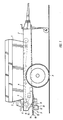
- the centrifugal fertilizer spreader designed as a large-area fertilizer spreader, is equipped with a storage container 1, a frame 2, and a carriage equipped with running wheels 3.
- a storage container 1 In the lower area of the storage container 1 there is the conveyor belt 4, which can be driven by an articulated shaft by a tractor pulling the large area spreader.
- the outlet opening 7, which can be adjusted via the slide 6, is arranged in the rear area 5 of the storage container 1.
- the scattering element designed as a centrifugal spreader 9 is arranged in the area of the rear outlet opening 7 or the rear end 8 of the conveyor belt 4.
- the centrifugal spreader 9 has the gear 10, which is arranged on brackets 11 on the frame 2 of the large-area fertilizer spreader.
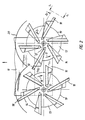
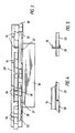
- the centrifugal disks 13 are arranged in a rotationally fixed manner on the drive shafts 12 which project upright from the transmission 10. The centrifugal disks 13 are also driven by the propeller shaft via the gear 10. The centrifugal disks 13 have the throwing elements 14. Via the conveyor belt 4, the fertilizer or sewage sludge or other materials to be discharged located in the storage container 1 is discharged via the outlet opening 7 and the guide funnel 15 fed to the centrifugal discs 13. The centrifugal disks 13 are driven in the opposite direction according to the arrows 16 and 17. Below the throwing blades 14 and the centrifugal disks 13, the clearing elements 18 projecting downwards from the throwing blades 14 and the centrifugal disks 13 are attached.
- the clearing elements 18 are screwed onto the throwing blades 14. However, it is also conceivable that the clearing elements 18 are arranged on the centrifugal disks 13 in the region of the individual throwing blades 14 or between the throwing blades. Two clearing elements 18 are provided for each centrifugal disc 13 and are arranged opposite one another. The clearing elements 18 preferably describe a larger orbit than the throwing elements 14 or the outer edge 19 of the centrifugal disks 13. Thus, the outer edge of the broaching elements 18 protrude beyond the outer edge of the throwing elements 14 and the outer edge 19 of the centrifugal discs 13.
- the guide and protective screen 20 is arranged on the frame 2 or the holding element 11, by means of which it is ensured that the fertilizer to be applied, such as lime, chicken manure, etc., is not thrown off to the front.
- the fertilizer that got into the space between the guide and protective screen 20, the holding elements 11 and the gear 10 on the one hand and the throwing blades 14 and the centrifugal discs 13 is cleared out of this area by the clearing elements 18, so that the fertilizer that gets into this space does not adhere can throw the throwing blades 14 or centrifugal disks 13.
- the clearing elements 18 additionally produce "wind", by means of which, in particular, lighter fertilizer, such as, for example, chicken manure, is blown out of this area. Very moist fertilizer is pushed out by the clearing elements 18, which can be designed, for example, as blades, and thrown off due to the centrifugal force generated by the rotation.
Landscapes
- Life Sciences & Earth Sciences (AREA)
- Soil Sciences (AREA)
- Environmental Sciences (AREA)
- Fertilizing (AREA)
- Filling Or Emptying Of Bunkers, Hoppers, And Tanks (AREA)
Applications Claiming Priority (2)
| Application Number | Priority Date | Filing Date | Title |
|---|---|---|---|
| DE19883829437 DE3829437A1 (de) | 1988-08-31 | 1988-08-31 | Zentrifugalduengerstreuer, insbesondere grossflaechenduengerstreuer |
| DE3829437 | 1988-08-31 |
Publications (2)
| Publication Number | Publication Date |
|---|---|
| EP0356631A2 true EP0356631A2 (fr) | 1990-03-07 |
| EP0356631A3 EP0356631A3 (fr) | 1990-10-03 |
Family
ID=6361913
Family Applications (1)
| Application Number | Title | Priority Date | Filing Date |
|---|---|---|---|
| EP19890110457 Withdrawn EP0356631A3 (fr) | 1988-08-31 | 1989-06-09 | Distributeur centrifuge d'engrais, notamment distributeur à grande couverture |
Country Status (2)
| Country | Link |
|---|---|
| EP (1) | EP0356631A3 (fr) |
| DE (1) | DE3829437A1 (fr) |
Cited By (1)
| Publication number | Priority date | Publication date | Assignee | Title |
|---|---|---|---|---|
| US20120055130A1 (en) * | 2010-09-01 | 2012-03-08 | Briggs & Stratton Corporation | Lawn mower and spreader system |
Family Cites Families (3)
| Publication number | Priority date | Publication date | Assignee | Title |
|---|---|---|---|---|
| AT219328B (de) * | 1957-03-28 | 1962-01-25 | Sigmund Stokland | Einrichtung zum Streuen von Dünger oder anderem körnigem Gut |
| NL8105285A (nl) * | 1981-11-23 | 1983-06-16 | Lely Nv C Van Der | Inrichting voor het verspreiden van korrel- en/of poedervormig materiaal. |
| DE3313892C2 (de) * | 1983-04-16 | 1986-11-13 | Amazonen-Werke H. Dreyer Gmbh & Co Kg, 4507 Hasbergen | Düngerstreuer |
-
1988
- 1988-08-31 DE DE19883829437 patent/DE3829437A1/de not_active Withdrawn
-
1989
- 1989-06-09 EP EP19890110457 patent/EP0356631A3/fr not_active Withdrawn
Cited By (1)
| Publication number | Priority date | Publication date | Assignee | Title |
|---|---|---|---|---|
| US20120055130A1 (en) * | 2010-09-01 | 2012-03-08 | Briggs & Stratton Corporation | Lawn mower and spreader system |
Also Published As
| Publication number | Publication date |
|---|---|
| EP0356631A3 (fr) | 1990-10-03 |
| DE3829437A1 (de) | 1990-03-01 |
Similar Documents
| Publication | Publication Date | Title |
|---|---|---|
| EP0104622B1 (fr) | Dispositif d'épandage de fumier, d'engrais et autres | |
| EP3721014B1 (fr) | Arrangement d'épandage pour véhicules d'épandage | |
| DE3505382A1 (de) | Zweischeibenduengerstreuer | |
| DE69805467T2 (de) | Verfahren um fliessendes Gut zu streuen, Vorrichtung für dieses Verfahren, und Wurfschaufel für diesen Streuer | |
| WO1996032005A1 (fr) | Epandeur d'engrais centrifuge | |
| EP0222337B1 (fr) | Distributeur à disques, spécialement pour engrais granulés | |
| EP0559242B1 (fr) | Expandeur centrifuge | |
| EP0160321B1 (fr) | Distributeur d'engrais centrifuge | |
| EP0356631A2 (fr) | Distributeur centrifuge d'engrais, notamment distributeur à grande couverture | |
| DE3924647C2 (fr) | ||
| DE1940922C3 (de) | Kunstdüngerstreuer | |
| EP0292874B1 (fr) | Distributeur à grand tonnage | |
| EP1088475A1 (fr) | Epandeur d'engrais | |
| DE3917210A1 (de) | Schleuderduengerstreuer | |
| CH692593A5 (de) | Fahrbare Einrichtung zur Verteilung von streufähigem Gut. | |
| DE2647721A1 (de) | Streugeraet fuer einen streuwagen mit kratzboden-ladeflaeche | |
| DE10043462C2 (de) | Winterdienst-Streugerät und Streuteller für Winterdienst-Streugerät | |
| DE19745441A1 (de) | Schleuderstreuer | |
| DE9002780U1 (de) | Trommel- und Scheibenhäcksler | |
| CH691788A5 (de) | Fahrbare Einrichtung zur Verteilung von streufähigem Gut. | |
| CH686855A5 (de) | Streuvorrichtung fuer Streugut, insbesondere fuer Mist und Kompost. | |
| DE4435836A1 (de) | Vorrichtung zum Verteilen von Mulch im Gelände | |
| DE3346950C1 (de) | Streuvorrichtung | |
| DE9416478U1 (de) | Vorrichtung zum Verteilen von Mulch im Gelände | |
| DE8710411U1 (de) | Fahrbare Streuvorrichtung für trockenes oder nasses Streugut, insbesondere Mist |
Legal Events
| Date | Code | Title | Description |
|---|---|---|---|
| PUAI | Public reference made under article 153(3) epc to a published international application that has entered the european phase |
Free format text: ORIGINAL CODE: 0009012 |
|
| AK | Designated contracting states |
Kind code of ref document: A2 Designated state(s): DE FR GB NL SE |
|
| PUAL | Search report despatched |
Free format text: ORIGINAL CODE: 0009013 |
|
| AK | Designated contracting states |
Kind code of ref document: A3 Designated state(s): DE FR GB NL SE |
|
| STAA | Information on the status of an ep patent application or granted ep patent |
Free format text: STATUS: THE APPLICATION HAS BEEN WITHDRAWN |
|
| 18W | Application withdrawn |
Withdrawal date: 19910927 |