EP0356670A1 - Sonde de courant à fibre optique - Google Patents
Sonde de courant à fibre optique Download PDFInfo
- Publication number
- EP0356670A1 EP0356670A1 EP89112741A EP89112741A EP0356670A1 EP 0356670 A1 EP0356670 A1 EP 0356670A1 EP 89112741 A EP89112741 A EP 89112741A EP 89112741 A EP89112741 A EP 89112741A EP 0356670 A1 EP0356670 A1 EP 0356670A1
- Authority
- EP
- European Patent Office
- Prior art keywords
- fiber
- perot
- current sensor
- fiber optic
- fabry
- Prior art date
- Legal status (The legal status is an assumption and is not a legal conclusion. Google has not performed a legal analysis and makes no representation as to the accuracy of the status listed.)
- Granted
Links
- 239000000835 fiber Substances 0.000 claims abstract description 51
- 230000000694 effects Effects 0.000 claims abstract description 31
- 230000003287 optical effect Effects 0.000 claims abstract description 21
- 239000004020 conductor Substances 0.000 claims abstract description 15
- 230000008878 coupling Effects 0.000 claims abstract description 14
- 238000010168 coupling process Methods 0.000 claims abstract description 14
- 238000005859 coupling reaction Methods 0.000 claims abstract description 14
- 230000001427 coherent effect Effects 0.000 claims abstract description 13
- 230000005540 biological transmission Effects 0.000 claims description 37
- 239000003365 glass fiber Substances 0.000 claims description 21
- 230000010287 polarization Effects 0.000 claims description 16
- 238000001514 detection method Methods 0.000 claims description 13
- VYPSYNLAJGMNEJ-UHFFFAOYSA-N Silicium dioxide Chemical compound O=[Si]=O VYPSYNLAJGMNEJ-UHFFFAOYSA-N 0.000 claims description 6
- 238000005259 measurement Methods 0.000 description 10
- 239000013307 optical fiber Substances 0.000 description 10
- 230000035945 sensitivity Effects 0.000 description 6
- 238000011156 evaluation Methods 0.000 description 3
- 238000005452 bending Methods 0.000 description 2
- 238000005253 cladding Methods 0.000 description 1
- 230000001419 dependent effect Effects 0.000 description 1
- 238000010586 diagram Methods 0.000 description 1
- 238000005305 interferometry Methods 0.000 description 1
- 238000000034 method Methods 0.000 description 1
- 230000010363 phase shift Effects 0.000 description 1
- 238000002310 reflectometry Methods 0.000 description 1
- 230000000717 retained effect Effects 0.000 description 1
- 238000011896 sensitive detection Methods 0.000 description 1
- 238000004804 winding Methods 0.000 description 1
Images

Classifications
-
- G—PHYSICS
- G01—MEASURING; TESTING
- G01R—MEASURING ELECTRIC VARIABLES; MEASURING MAGNETIC VARIABLES
- G01R15/00—Details of measuring arrangements of the types provided for in groups G01R17/00 - G01R29/00, G01R33/00 - G01R33/26 or G01R35/00
- G01R15/14—Adaptations providing voltage or current isolation, e.g. for high-voltage or high-current networks
- G01R15/24—Adaptations providing voltage or current isolation, e.g. for high-voltage or high-current networks using light-modulating devices
- G01R15/245—Adaptations providing voltage or current isolation, e.g. for high-voltage or high-current networks using light-modulating devices using magneto-optical modulators, e.g. based on the Faraday or Cotton-Mouton effect
- G01R15/246—Adaptations providing voltage or current isolation, e.g. for high-voltage or high-current networks using light-modulating devices using magneto-optical modulators, e.g. based on the Faraday or Cotton-Mouton effect based on the Faraday, i.e. linear magneto-optic, effect
Definitions
- the invention relates to a fiber-optic current sensor with a single-mode optical waveguide, which is wound around an electrical conductor, and means for coupling in coherent light and detecting the magneto-optical Faraday effect.
- glass fibers can be used as current sensors due to the magneto-optical Faraday effect.
- the glass fiber is wound around an electrical conductor and the rotation induced by the current of the polarization of the light guided in the glass fiber is measured.
- Such a fiber-optic current sensor is, for example, from "Optical fiber current measurement” from AJ Rogers, Proc. of the Soc. of Photo-opt. Instr. Engineers, SPIE 374, 1983.
- Light from a He-Ne laser is coupled in at one end of the glass fiber.
- At the other end of the A Wollaston prism is arranged in glass fiber, which splits the light in terms of polarization and supplies two photodetectors.
- the problem with the known sensors is that, on the one hand, a large number of windings and thus also a long optical waveguide is required for high sensitivity, but on the other hand a short optical waveguide is desirable in order to minimize the influence of imperfections in the glass fiber.
- the object of the invention is to provide a fiber-optic current sensor with a single-mode optical waveguide, which is wound around an electrical conductor, and means for coupling in coherent light and detecting the magneto-optical To create Faraday effect, which has a high sensitivity with small geometric dimensions.
- the solution is that in a fiber-optic current sensor mentioned at the outset, the single-mode optical waveguide is designed as a fiber-optic Fabry-Perot, which has a length that corresponds to half or a multiple of half the beat length of the coupled light and which has the shape of a helix which circles the electrical conductor exactly N times, where N is a positive integer, and that the means for coupling in coherent light comprise a laser stabilized to a resonance frequency of the fiber optic Fabry-Perot.
- the fiber optic Fabry-Perot is preferably a single-mode quartz glass fiber provided with a mirror at both ends and has a finesse of less than 100.
- the fiber optic Fabry-Perot can be operated either in transmission or in reflection.
- the basis of the circular polarization states is best suited for describing the Faraday effect in single-mode optical fibers.
- the input states (right or left circular polarization) experience a different phase rotation per path length (birefringence) when the optical fiber bends.
- the distance by which the two polarization states have a phase difference of 360 ° is called the beat length.
- the fiber optic Fabry-Perot according to the invention in the form of a helix must meet the following conditions.
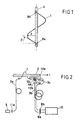
- the helix 1 shows a fiber optic Fabry-Perot 1 according to the invention. It has the shape of a helix with a radius R, a length s and an angle of inclination ⁇ . According to a preferred embodiment, the helix circles the electrical conductor 2, which lies essentially on the axis of the helix, exactly once.
- the fiber optic Fabry-Perot 1 is formed by a single-mode optical waveguide, which is provided at its ends with dielectric or metallic mirrors 9a, 9b. In transmission, the mirrors 9a, 9b can be identical. In contrast, the mirror in which the light is coupled in should have a lower reflectivity in reflection.
- the gain factor for the Faraday effect is determined by the finesse of the fiber optic Fabry-Perot 1. However, the line width of the coupled light determines the maximum gain factor that can be achieved.
- the single-mode optical waveguide is a weakly birefringent quartz glass fiber.
- the helix has a radius R of more than 10 mm and an angle of inclination ⁇ of about 30 °.
- the finesse F of the fiber optic Fabry-Perot is not greater than 100.
- the radius of the helix is as large as possible.
- the length s of the fiber optic Fabry-Perot will be set to an integer multiple of the beat length.
- the helix can circle the electrical conductor exactly twice (generally exactly N times). It is only necessary to ensure that condition (III) is met.
- FIG. 2 shows a fiber-optic current sensor in which the fiber-optic Fabry-Perot is operated in transmission and the Faraday effect is measured in direct detection.
- the light from a laser 5 is linearly polarized with a polarizer 11a and coupled into a first transmission line 3a.
- a strongly birefringent glass fiber is used as the optical transmission line 3a, so that the polarization of the light is retained during the transmission.
- the polarizer 11a is aligned with respect to the mutually orthogonal birefringence axes of the glass fiber so that the The direction of polarization of the coupled light encloses an angle of 45 ° with the birefringence axes.
- the transmitted light is coupled into a fiber optic Fabry-Perot 1 according to the invention, which surrounds an electrical conductor 2 and thus a current i.
- the light transmitted by the fiber optic Fabry-Perot is decoupled with a lens 12c and broken down into two partial beams with a beam splitter 4a, which with two polarizers 11a, 11b with respect to + 45 ° and -45 ° components can be analyzed.
- the analyzed partial beams are respectively with a lens 12a. 12b in a second resp. third transmission line 3b or 3c coupled and to photodetectors 8a or. 8b led.
- the other two need not be highly birefringent single-mode optical fibers; multimode glass fibers are sufficient. From the intensities I1, I2 detected by the photodetectors 8a, 8b, the current i is determined in a downstream evaluation electronics 10.
- the quotient (I1 - I2) / (I1 + I2) is proportional to ⁇ and thus proportional to the current i.
- the laser 5 is stabilized to a resonance frequency of the fiber-optic Fabry-Perot.
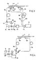
- FIG. 3 shows an embodiment with heterodyne detection.
- parts that have already been described in Fig. 1 are provided with corresponding reference numerals.
- a temperature-stabilized single-mode laser 5 is activated by means of a frequency controller 13 e.g. frequency modulated with 10 kHz.
- the modulation is said to correspond to a fraction of the bandwidth of the fiber optic Fabry-Perot 1.
- the laser light is collimated in a lens 12g and then split into two linearly polarized partial beams in a polarizing beam splitter 4b. Each of the two partial beams is respectively in an acousto-optical modulator 14a. 14b frequency modulated.
- the two modulation frequencies are, for example, 40.0 MHz or 40.1 MHz and, according to a preferred embodiment, differ by 100 kHz.
- Two mirrors 9c, 9d and a second polarizing beam splitter 4c bring the two modulated partial beams together again.
- the modulated beam is then coupled with a lens 12c into a polarization-maintaining first transmission line 3a.
- a quarter wave retarder 6c and a beam splitter 4a are arranged at the end of the transmission line 3a.
- a first partial beam of the beam splitter 4a is analyzed as a reference with a polarizer 11a, coupled into a second transmission line 3b with a lens 12b and then measured by the photodetector 8a.
- a second partial beam of the beam splitter 4a is coupled into the fiber optic Fabry-Perot 1, which is operated in transmission, with a lens 12d, is then analyzed by a polarizer 11b, is coupled with a lens 12a into a third transmission line 3c and then as the photodetector 8b Measurement signal detected.
- the measurement signal is fed back to the frequency controller 13, which uses it to generate an error signal for controlling the Modulation of the laser 5 is extracted and, on the other hand, filtered in a bandpass filter 15, whose pass frequency in the present example is 100 kHz.
- the phase difference between the measurement signal filtered in this way and the reference signal is determined in evaluation electronics 10 (phase meter) and the current i is determined therefrom.
- the measuring arrangement described is characterized by two principles, namely by a feedback loop, which regulates the laser frequency to a resonance frequency of the fiber optic Fabry-Perot, and by an accurate measurement of the phase difference between the two polarization states. Because of the rapidly changing amplitude in the vicinity of the resonance, it is important to measure the phase difference regardless of the amplitude.
- the heterodyne polarization interferometry used in the second exemplary embodiment is known as such and is described in the publication "High sensitivity Fabry-Perot optical fiber sensor for the measurement of mechanical force", F. Maystre et al., Optical Fiber Sensors, 1988 Tech. Digest Series, 2 (Opt. Soc. Of America) pp. 424-432, described in detail.
- FIG. 4 shows a fiber optic current sensor in which the fiber optic Fabry-Perot is operated in transmission and the Faraday effect is measured with a Sagnac interferometer.
- a laser 5 supplies two orthogonally polarized partial beams A, B. These are separated in a polarizing beam splitter 4b.
- the first partial beam A runs over a first transmission line 3a, a first quarter-wave retarder 6a, the fiber optic Fabry-Perot 1, undergoing a phase shift, a second quarter-wave retarder 6b and a second transmission line 6b back to the polarizing beam splitter 4b.
- Partial beam B traverses the same route, but in the opposite direction.
- a beam splitter 4a decouples the phase-shifted partial beams A, B returning from the polarizing beam splitter 4b, so that they can be analyzed in the manner already described.
- FIG. 5 shows a fiber optic current sensor in which the fiber optic Fabry-Perot is operated in reflection and the Faraday effect is measured in direct detection.
- a quarter-wave retarder 6b (converts linearly polarized light into circularly polarized and vice versa), which creates the connection between the fiber optic Fabry-Perot 1 and an optical transmission line 3a.
- a beam splitter 4a is provided from the transmission line 3a.
- the light to be coupled is supplied by a laser 5 (e.g. a laser diode) with a polarizer 11a connected downstream.
- the outcoupled light passes through a quarter wave retarder 6a and a cross polarizer 7 and then falls with an intensity I1 resp. I2 on two photodetectors 8a, respectively.
- An electronic evaluation unit 10 determines the current i flowing in the electrical conductor 2 from the two measured intensities I 1 and I 2.
- the cross polarizer 7 is oriented with respect to the birefringence axes of the transmission line 3a in such a way that it delivers two beams with a polarization direction of +/- 45 °.
- the fiber optic current sensor is insensitive to temperature fluctuations.
- the dynamics of the current sensor is limited by the resonance range of the fiber optic Fabry-Perot (approx. +/- 45 °).
- F finesse of the Fabry-Perot.
- the sensitivity at the edge of the measuring range is still around 85% of the maximum value (in the middle of the resonance).
- the relative sensitivity is given by the accuracy of the phase measurement, i.e. through the detection method and the ratio of signal to noise in comparison to dynamics.
- the finesse of the Fabry-Perot is adapted to the desired measuring range. If the fiber optic Fabry-Perot e.g. consists of a quartz glass fiber and the measuring range should be +/- 2000 A, then the finesse should not be greater than 100, which corresponds to a gain factor of about 66.
- FIG. 6a shows two preferred embodiments of the quarter-wave retarder 6a, 6b, 6c.
- a 90 ° delay is generated by a weakly birefringent single-mode glass fiber 16 bent into a loop.
- the birefringence axes (dashed arrows) of the Transmission line 3a are 45 ° compared to the slow or the fast axis of the curved glass fiber 16 rotated.
- a first GRIN-rod lens 12e is connected to the transmission line 3a, and a second GRIN-rod Lens 12f is attached to a mirror 9a of the fiber optic Fabry-Perot 1.
- heterodyne detection can e.g. can also be used advantageously in conjunction with a fiber optic Fabry-Perot operated in reflection.
- other polarization interferometers can also be used to measure the Faraday rotation in the fiber optic Fabry-Perot according to the invention.
- the invention provides a fiber-optic current sensor which has a high sensitivity with a short fiber length and thereby reduces disturbances caused by inhomogeneities of the optical waveguides to a minimum.
Landscapes
- Engineering & Computer Science (AREA)
- Power Engineering (AREA)
- Physics & Mathematics (AREA)
- General Physics & Mathematics (AREA)
- Measuring Instrument Details And Bridges, And Automatic Balancing Devices (AREA)
Applications Claiming Priority (2)
| Application Number | Priority Date | Filing Date | Title |
|---|---|---|---|
| CH324688 | 1988-08-31 | ||
| CH3246/88 | 1988-08-31 |
Publications (2)
| Publication Number | Publication Date |
|---|---|
| EP0356670A1 true EP0356670A1 (fr) | 1990-03-07 |
| EP0356670B1 EP0356670B1 (fr) | 1993-10-06 |
Family
ID=4251815
Family Applications (1)
| Application Number | Title | Priority Date | Filing Date |
|---|---|---|---|
| EP19890112741 Expired - Lifetime EP0356670B1 (fr) | 1988-08-31 | 1989-07-12 | Sonde de courant à fibre optique |
Country Status (2)
| Country | Link |
|---|---|
| EP (1) | EP0356670B1 (fr) |
| DE (1) | DE58905825D1 (fr) |
Cited By (9)
| Publication number | Priority date | Publication date | Assignee | Title |
|---|---|---|---|---|
| EP0477415A1 (fr) * | 1990-09-28 | 1992-04-01 | Asea Brown Boveri Ag | Transducteur optique de courant |
| US5136236A (en) * | 1989-09-25 | 1992-08-04 | Asea Brown Boveri Ltd. | Arrangement for voltage measurement in a gis installation |
| DE4224190A1 (de) * | 1992-07-22 | 1994-01-27 | Abb Research Ltd | Faseroptischer Stromsensor |
| US5475298A (en) * | 1991-01-16 | 1995-12-12 | British Technology Group Ltd. | Method and apparatus for measurements dependent on the faraday effect using polarized counter-propagating light |
| EP0507742B1 (fr) * | 1991-04-04 | 1996-10-23 | Centre Suisse D'electronique Et De Microtechnique S.A. | Capteur optique de courant électrique |
| US5963026A (en) * | 1994-08-23 | 1999-10-05 | Siemens Aktiengesellschaft | Method and device for the measurement of electric currents in at least two measuring ranges |
| CN105852814A (zh) * | 2016-04-22 | 2016-08-17 | 中国医学科学院生物医学工程研究所 | 基于f-p腔光纤声传感器的磁声信号检测及成像系统 |
| RU2752341C1 (ru) * | 2020-09-25 | 2021-07-26 | Акционерное общество "Центральное конструкторское бюро "ФОТОН" (АО "ЦКБ "ФОТОН") | Измеритель тока оптический двухканальный |
| CN113933764A (zh) * | 2021-09-30 | 2022-01-14 | 杭州电子科技大学 | 基于铁磁薄膜与法布里珀罗腔的磁场传感系统 |
Families Citing this family (1)
| Publication number | Priority date | Publication date | Assignee | Title |
|---|---|---|---|---|
| CN106199124A (zh) * | 2016-06-24 | 2016-12-07 | 桂林创研科技有限公司 | 光纤电流感测光路系统 |
Citations (2)
| Publication number | Priority date | Publication date | Assignee | Title |
|---|---|---|---|---|
| FR2475230A1 (fr) * | 1980-02-01 | 1981-08-07 | Electricite De France | Dispositif de mesure d'intensite electrique dans un conducteur par determination des variations de marche d'un faisceau polarise dans un milieu optique materiel soumis au champ magnetique cree par le courant |
| EP0108671B1 (fr) * | 1982-10-28 | 1989-01-18 | Commissariat A L'energie Atomique | Dispositif de mesure de température et/ou d'intensité électrique à effet Faraday |
-
1989
- 1989-07-12 DE DE89112741T patent/DE58905825D1/de not_active Expired - Fee Related
- 1989-07-12 EP EP19890112741 patent/EP0356670B1/fr not_active Expired - Lifetime
Patent Citations (2)
| Publication number | Priority date | Publication date | Assignee | Title |
|---|---|---|---|---|
| FR2475230A1 (fr) * | 1980-02-01 | 1981-08-07 | Electricite De France | Dispositif de mesure d'intensite electrique dans un conducteur par determination des variations de marche d'un faisceau polarise dans un milieu optique materiel soumis au champ magnetique cree par le courant |
| EP0108671B1 (fr) * | 1982-10-28 | 1989-01-18 | Commissariat A L'energie Atomique | Dispositif de mesure de température et/ou d'intensité électrique à effet Faraday |
Cited By (11)
| Publication number | Priority date | Publication date | Assignee | Title |
|---|---|---|---|---|
| US5136236A (en) * | 1989-09-25 | 1992-08-04 | Asea Brown Boveri Ltd. | Arrangement for voltage measurement in a gis installation |
| EP0477415A1 (fr) * | 1990-09-28 | 1992-04-01 | Asea Brown Boveri Ag | Transducteur optique de courant |
| US5475298A (en) * | 1991-01-16 | 1995-12-12 | British Technology Group Ltd. | Method and apparatus for measurements dependent on the faraday effect using polarized counter-propagating light |
| EP0507742B1 (fr) * | 1991-04-04 | 1996-10-23 | Centre Suisse D'electronique Et De Microtechnique S.A. | Capteur optique de courant électrique |
| DE4224190A1 (de) * | 1992-07-22 | 1994-01-27 | Abb Research Ltd | Faseroptischer Stromsensor |
| DE4224190B4 (de) * | 1992-07-22 | 2007-01-18 | Abb Research Ltd. | Faseroptischer Stromsensor |
| US5963026A (en) * | 1994-08-23 | 1999-10-05 | Siemens Aktiengesellschaft | Method and device for the measurement of electric currents in at least two measuring ranges |
| CN105852814A (zh) * | 2016-04-22 | 2016-08-17 | 中国医学科学院生物医学工程研究所 | 基于f-p腔光纤声传感器的磁声信号检测及成像系统 |
| RU2752341C1 (ru) * | 2020-09-25 | 2021-07-26 | Акционерное общество "Центральное конструкторское бюро "ФОТОН" (АО "ЦКБ "ФОТОН") | Измеритель тока оптический двухканальный |
| CN113933764A (zh) * | 2021-09-30 | 2022-01-14 | 杭州电子科技大学 | 基于铁磁薄膜与法布里珀罗腔的磁场传感系统 |
| CN113933764B (zh) * | 2021-09-30 | 2023-09-08 | 杭州电子科技大学 | 基于铁磁薄膜与法布里珀罗腔的磁场传感系统 |
Also Published As
| Publication number | Publication date |
|---|---|
| EP0356670B1 (fr) | 1993-10-06 |
| DE58905825D1 (de) | 1993-11-11 |
Similar Documents
| Publication | Publication Date | Title |
|---|---|---|
| EP1154278B1 (fr) | Capteur de courant à fibre optique | |
| EP0430060B1 (fr) | Ampèremètre à fibre optique | |
| DE3049033C2 (fr) | ||
| DE69131214T2 (de) | Stromsonde mit Faraday-Effekt | |
| EP0856737B1 (fr) | Capteur de courant magnéto optique | |
| DE69107549T2 (de) | Optischer Faserkreisel. | |
| DE69208296T2 (de) | Faseroptischer Kreisel | |
| DE19703128A9 (de) | Magnetooptischer Stromsensor | |
| EP1174719A1 (fr) | Capteur de courant à fibre optique | |
| DE69102543T2 (de) | Optischer faserkreisel. | |
| DE3609507A1 (de) | Faseroptisches interferometer | |
| DE69614384T2 (de) | Optische leistungsstabilisierung für interferometrisches optisches glasfaser-gyroskop | |
| EP0356670B1 (fr) | Sonde de courant à fibre optique | |
| DE69025186T2 (de) | Production d'ondes porteuses optiques par effet stimule de diffusion brillouin | |
| EP0554211A2 (fr) | Procédés de mesure d'une force utilisant une fibre optique | |
| EP1499859A1 (fr) | Detecteur a laser a fibre a haute resolution | |
| DE19628200A1 (de) | Vorrichtung und Verfahren zur Durchführung interferometrischer Messungen | |
| DE3311809A1 (de) | Interferometrisches, eichbares fabry-perot-sensorsystem mit doppelbrechendem monomode-lichtwellenleiter | |
| EP0854354B1 (fr) | Méthode pour compenser l'influence de la température sur les signaux mesurés par un capteur à fibre optique | |
| EP1421393B1 (fr) | Capteurs de courant optiques | |
| DE3726411A1 (de) | Faseroptischer magnetfeldsensor | |
| EP0864098B1 (fr) | Procede et dispositif de mesure d'une grandeur, notamment un courant electrique, avec une haute resolution de mesure | |
| EP0529339B1 (fr) | Capteur à fibre optique | |
| EP0241766A2 (fr) | Dispositif détecteur | |
| DE4224190B4 (de) | Faseroptischer Stromsensor |
Legal Events
| Date | Code | Title | Description |
|---|---|---|---|
| PUAI | Public reference made under article 153(3) epc to a published international application that has entered the european phase |
Free format text: ORIGINAL CODE: 0009012 |
|
| AK | Designated contracting states |
Kind code of ref document: A1 Designated state(s): CH DE LI SE |
|
| 17P | Request for examination filed |
Effective date: 19900810 |
|
| 17Q | First examination report despatched |
Effective date: 19920605 |
|
| GRAA | (expected) grant |
Free format text: ORIGINAL CODE: 0009210 |
|
| AK | Designated contracting states |
Kind code of ref document: B1 Designated state(s): CH DE LI SE |
|
| PG25 | Lapsed in a contracting state [announced via postgrant information from national office to epo] |
Ref country code: SE Effective date: 19931006 |
|
| REF | Corresponds to: |
Ref document number: 58905825 Country of ref document: DE Date of ref document: 19931111 |
|
| PGFP | Annual fee paid to national office [announced via postgrant information from national office to epo] |
Ref country code: DE Payment date: 19940716 Year of fee payment: 6 |
|
| PGFP | Annual fee paid to national office [announced via postgrant information from national office to epo] |
Ref country code: CH Payment date: 19940721 Year of fee payment: 6 |
|
| PLBE | No opposition filed within time limit |
Free format text: ORIGINAL CODE: 0009261 |
|
| STAA | Information on the status of an ep patent application or granted ep patent |
Free format text: STATUS: NO OPPOSITION FILED WITHIN TIME LIMIT |
|
| 26N | No opposition filed | ||
| PG25 | Lapsed in a contracting state [announced via postgrant information from national office to epo] |
Ref country code: LI Effective date: 19950731 Ref country code: CH Effective date: 19950731 |
|
| REG | Reference to a national code |
Ref country code: CH Ref legal event code: PL |
|
| PG25 | Lapsed in a contracting state [announced via postgrant information from national office to epo] |
Ref country code: DE Effective date: 19960501 |