EP0356679A1 - Seringue d'injection à usage unique - Google Patents
Seringue d'injection à usage unique Download PDFInfo
- Publication number
- EP0356679A1 EP0356679A1 EP89113040A EP89113040A EP0356679A1 EP 0356679 A1 EP0356679 A1 EP 0356679A1 EP 89113040 A EP89113040 A EP 89113040A EP 89113040 A EP89113040 A EP 89113040A EP 0356679 A1 EP0356679 A1 EP 0356679A1
- Authority
- EP
- European Patent Office
- Prior art keywords
- valve
- injection
- housing
- injection syringe
- syringe according
- Prior art date
- Legal status (The legal status is an assumption and is not a legal conclusion. Google has not performed a legal analysis and makes no representation as to the accuracy of the status listed.)
- Granted
Links
Images
Classifications
-
- A—HUMAN NECESSITIES
- A61—MEDICAL OR VETERINARY SCIENCE; HYGIENE
- A61M—DEVICES FOR INTRODUCING MEDIA INTO, OR ONTO, THE BODY; DEVICES FOR TRANSDUCING BODY MEDIA OR FOR TAKING MEDIA FROM THE BODY; DEVICES FOR PRODUCING OR ENDING SLEEP OR STUPOR
- A61M5/00—Devices for bringing media into the body in a subcutaneous, intra-vascular or intramuscular way; Accessories therefor, e.g. filling or cleaning devices, arm rests
- A61M5/178—Syringes
- A61M5/28—Syringe ampoules or carpules, i.e. ampoules or carpules provided with a needle
- A61M5/281—Syringe ampoules or carpules, i.e. ampoules or carpules provided with a needle using emptying means to expel or eject media, e.g. pistons, deformation of the ampoule, or telescoping of the ampoule
- A61M5/282—Syringe ampoules or carpules, i.e. ampoules or carpules provided with a needle using emptying means to expel or eject media, e.g. pistons, deformation of the ampoule, or telescoping of the ampoule by compression of deformable ampoule or carpule wall
-
- A—HUMAN NECESSITIES
- A61—MEDICAL OR VETERINARY SCIENCE; HYGIENE
- A61M—DEVICES FOR INTRODUCING MEDIA INTO, OR ONTO, THE BODY; DEVICES FOR TRANSDUCING BODY MEDIA OR FOR TAKING MEDIA FROM THE BODY; DEVICES FOR PRODUCING OR ENDING SLEEP OR STUPOR
- A61M5/00—Devices for bringing media into the body in a subcutaneous, intra-vascular or intramuscular way; Accessories therefor, e.g. filling or cleaning devices, arm rests
- A61M5/50—Devices for bringing media into the body in a subcutaneous, intra-vascular or intramuscular way; Accessories therefor, e.g. filling or cleaning devices, arm rests having means for preventing re-use, or for indicating if defective, used, tampered with or unsterile
-
- A—HUMAN NECESSITIES
- A61—MEDICAL OR VETERINARY SCIENCE; HYGIENE
- A61M—DEVICES FOR INTRODUCING MEDIA INTO, OR ONTO, THE BODY; DEVICES FOR TRANSDUCING BODY MEDIA OR FOR TAKING MEDIA FROM THE BODY; DEVICES FOR PRODUCING OR ENDING SLEEP OR STUPOR
- A61M5/00—Devices for bringing media into the body in a subcutaneous, intra-vascular or intramuscular way; Accessories therefor, e.g. filling or cleaning devices, arm rests
- A61M5/178—Syringes
- A61M5/31—Details
- A61M2005/3128—Incorporating one-way valves, e.g. pressure-relief or non-return valves
Definitions
- the invention relates to a disposable injection syringe which expediently has an injection cannula connected to a container for the injection liquid, so that simple handling results.
- hypodermic syringes in particular hypodermic needles, which are intended for single use so that they cannot be reused after their intended use.
- Injection syringes in particular, in which the injection cannula with the filled container for the injection liquid already forms a prefabricated structural unit, are said to be unsuitable for reuse. With known injection syringes, this requirement is not met, or at most poorly.
- the invention is also based on the object of creating an injection syringe or an injection cannula of the type mentioned, in which disadvantages are known Solutions are avoided and which ensures, in particular in a simple manner, that repeated use is inevitably prevented after their intended use.
- a disposable injection syringe which has an injection cannula connected to a film container or a similar container for the injection liquid, this injection cannula being assigned a valve which automatically blocks against sucking back in the direction of the container. Since syringes, the injection liquid chamber of which are non-detachably connected to the injection cannula, can only be sucked through this injection cannula again and thereby filled, the refilling of the chamber without destruction of the injection syringe is avoided with certainty by the design according to the invention.
- the injection cannula itself has no connecting sleeve at its end facing away from the tip for detachable connection to injection pumps, so that it can also no longer be attached to other injection containers, for example in the manner of thrust piston pumps, and thus also from use in connection with such containers is excluded.
- the valve is designed as a spring-free check valve in particular, the valve body of which is arranged to move freely within a valve chamber between a closed position and an open position.
- the valve it is also conceivable to design the valve so that it is inevitably closed at the end of the one-time injection process, for example by clogging the injection cannula.
- valve could also be provided within the injection cannula or structurally combined with it.
- valve is expedient outside the injection cannula, in particular provided immediately adjacent to its inlet side, so that injection cannulas can be used which are formed only by pipe sections.
- the valve has a disk-shaped valve body which is movable or movable in a valve housing, the valve housing or the valve seat expediently consisting of a thermoplastic polyester or the valve body made of a polyurethane.
- the design according to the invention is also suitable for relatively fine injection needles with a diameter of, for example, about 5/10 mm, the valve housing expediently having an outer width which corresponds to at most 9 or 10 times the outer diameter of the cannula, preferably being smaller in comparison.
- the axial extent of the valve housing can in turn be approximately in the order of magnitude of its outer width or slightly above.
- the axial extent of the valve body is expediently only of the order of magnitude of the outer diameter of the injection cannula.
- the closing seat of the valve is formed by an end cover of a housing, namely in particular the valve housing, is particularly advantageous.
- This end cover is expediently sleeve-shaped and inserted into a sleeve-shaped end part of the housing essentially in a non-detachable manner, for example by being blown in, so that it cannot be removed for filling the container or for removing the valve body or opening the valve in any other way.
- valve cover lies essentially completely within the housing, preferably with its associated end face is essentially flush or gap-free and therefore offers no possibilities To use tools for the purpose of its removal.
- the valve cover can also consist of a thermoplastic polyester, for example the same material as the rest of the valve housing, it being conceivable to bond the valve housing cover and the valve housing in an adhesive manner, in particular by means of thermoplastic welding, so that even the most careful attempts to open them fail.
- a secure connection between the housing and the end cover can also be achieved if the latter has an enlarged collar which engages in a corresponding inner groove in the housing and is at a distance from the outer end face of the end cover, so that it cannot be reached from the outside.
- This covenant can e.g. then be provided on the inner end face of the end cover and reach at most about half the axial extent of the end cover.
- An inlet opening of the valve housing is expediently located at the end of the valve housing facing away from the injection cannula, wherein it is advantageously formed by the front cover itself and lies in the center thereof.
- the axial extent of the end cover can be approximately in the order of half of the axial extent of the valve housing, while its outer width, in particular that of the collar, is at most a quarter smaller than the outer width of the valve housing.
- the valve body is movably mounted in a ribbed valve chamber, wherein axial ribs for radial guidance and radial ribs for axially limiting the stop of the valve body are preferably provided in the open position.
- the ends of the radial ribs expediently surround the inlet side of the injection cannula, while their side surfaces narrowed approximately radially, radially inward in the form of a segment of a circle Limit flow channels through which the injection liquid, coming from the axial ribs along the outer circumference of the valve body, can flow directly into the inlet end of the injection cannula.
- each radial rib is advantageously symmetrical about an axial plane of an associated axial rib, into which it merges in one piece in an angular manner and which extends to the end cover.
- Each radial rib advantageously has the same width as the associated axial rib, the width expediently being in the order of magnitude of 3 to 4 times the inside width of the valve space or 2 to 3 times the outside width of the valve body and four axial or Radial ribs are evenly distributed over the circumference.
- valve housing directly forms a needle carrier for the injection cannula, which is to be attached to the container exclusively via the valve housing. Since the end of the valve housing facing away from the injection cannula forms a substantially continuous flat end face and is therefore unsuitable for plug-in or similar connections, and because the inside width of the end cap, at around 1 mm, is only approximately twice as large as the outside width of the injection cannula the unit formed from the injection cannula and needle carrier is unsuitable for connection to other injection pumps.
- the injection cannula including the needle carrier or the valve, in such a way that it can be connected to a piston-pump-like injection pump or can be structurally combined with it.
- a Foil container made of plastic foil, aluminum foil or the like which is expediently made of two foil parts lying on top of one another and welded together along the common edge.
- the end of the injection cannula facing away from the cannula tip is advantageously fastened to the film container by sheathing or welding, this sheathing preferably being provided primarily for the valve housing or the needle carrier in such a way that it lies completely between the film parts and is covered by them.
- the container can be permanently connected to the valve housing or the needle carrier by welding, the welding expediently being provided essentially continuously over the entire circumference of the valve housing, on the end face facing the inside of the container, the end face facing away from it and expediently also every further end face. which is formed, for example, by a stepped outer shape of the valve housing. It is conceivable to also carry out the welding between the valve housing and the end cover in the course of this welding.
- valve which keeps the interior of the container closed with respect to the injection cannula until it is used as intended and can then be opened irreversibly or resealable, for example by increasing the internal pressure in the container or a similar measure.
- This valve could be formed, for example, by the safety or non-return valve described, in which case the valve body could be held non-positively in its closed position.
- a closure in particular a tear-open closure, is provided as the valve, which is located in the outflow direction in front of the safety or non-return valve immediately adjacent to the inlet side of the valve housing.
- This closure can be done in a particularly simple manner a zone is formed in which the two film parts of the film container are attached to each other with a reduced predetermined breaking adhesive force, so that due to a predetermined increase in the internal pressure of the film container, the closure opens by itself and the line parts past the valve through the valve Valve housing to the injection cannula releases.
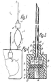
- the single-use injection syringe 1 has a film container 2 and an injection cannula 3 structurally combined with it via a needle carrier 4.
- the film container 2 consists of two superimposed rectangular or approximately square film parts 5, 6, which a pillow within their common marginal edges form-filled container chamber 7, which is approximately circular in view, and are non-detachably connected to one another from the outer circumference of this container chamber 7 up to its peripheral edges by an all-over weld connection.
- the injection cannula 3 protrudes at right angles over an outer edge, namely approximately in the middle of its width, the container chamber 7 being farther away from this edge than from the parallel edge facing away from it.
- the injection cannula 3 has a cannula tip 9.
- the injection cannula 3 is assigned a valve 10 in the form of a check valve, which has an approximately cylindrical valve housing 11 which is formed in one piece with the needle carrier 4.
- the valve housing 11, in which a circular disk-shaped valve body 12 is arranged to move freely, is essentially formed by a sleeve-shaped or cup-shaped component coaxial to the injection cannula 3, in the end part 14 of which is turned away from the injection cannula 3, a sleeve-shaped end cover 13 is inserted completely sunk .
- This end cover 13 has at its inner end a collar 15 projecting by a few tenths of a millimeter above its otherwise cylindrical outer circumference, which engages in a closely matched annular groove on the inner circumferential surface of the valve housing 11 with prestress.
- the inner circumferential surface of the valve housing 11 has essentially constant cross-sections in the region of the valve chamber 16 delimited by it up to the end face remote from the injection cannula 3, which are only interrupted by the inner ring groove mentioned.
- this inner circumferential surface can be provided with a phase-like, conical widening on the end face mentioned, which forms an insertion surface when the end cover 13 is pushed in. Instead of or in addition to this, such an insertion surface can also be provided only at the associated inner end of the end cover 13 or the annular collar 15.
- the inner, flat and annular disk-shaped end face of the end cover 13 forms the valve seat 17 for the flat valve closing surface of the valve body 12.
- the outside width of the valve body 12 is smaller than the inside width of the valve housing 11.
- the associated end wall 18 of the valve housing 11 forms the bottom the valve chamber, the injection cannula 3 passing through this bottom.
- axial ribs 19 which extend to the inner end face of the end cover 13 and thus directly adjacent to each position of the valve body 12 only with the necessary play lie to the outer circumference of the valve body 12.
- the axial ribs 19 merge into radial ribs 20, which have a larger rib height and whose head edges facing the valve seat 17 and lying in a common plane form a stop for the open position of the valve body 17.
- the essentially flat ends 22 of the radial ribs 20 facing one another or the central axis of the injection cannula 3 surround the inlet side 23 of the injection cannula 3, the inner end face of which is flush with the inner end face of the end wall 18.
- the radial distance of the ends 22 from the central axis of the inlet side 23 of the injection cannula 3 is greater than half its diameter, so that favorable flow conditions result and 22 through-slots remain free even between adjacent ends 22 when the radial ribs 20 are relatively wide.
- the end of the expediently metallic injection cannula 3 remote from the cannula tip 9 forms a shaft part 24 which is anchored non-detachably in the needle carrier 4 by injection and extends to the associated end face of the valve chamber 16.
- the needle carrier 4 is formed by a housing extension 25 of the valve housing 11, which connects in one piece to the end wall 18, projects exclusively to the outside and has an outer width which is less than half the outer width of the valve housing 11 or approximately 3 times as large as that Outside diameter of the injection cannula 3.
- the axial extent of the extension 25 is greater than the thickness of the end wall 18 and slightly larger than its outside width.
- the two film parts 5, 6 are fastened to these peripheral surfaces 26, 27, 28 and to the end surfaces 29, 30, 31 by welding such that each film part covers approximately half of each peripheral surface and half of each end surface and thereby the valve housing 11 and Needle carrier 4 and part of the injection cannula 3 are completely covered.
- the inner end face 29 of the valve housing 11 lies at a short distance from the container chamber 7.
- the inlet opening 32 for the valve 10 is provided, which is expediently formed by the central channel of the end cover 13.
- the two film parts 5, 6 form a closure 33 which can be opened by hydraulic pressure in that in its area the two film parts 5, 6 are connected to one another only with a reduced adhesive force and when detached from one another release a precisely delimited connecting channel between the container chamber 7 and the inlet opening 32.
- the injection syringe 1 can be handled very easily, with only the two film parts 5, 6 in the region of the container chamber 7 having to be pressed together with two fingers of one hand in order to eject the injection liquid.
- a refilling of the container chamber 7 is also ruled out due to the valve 10 which immediately closes against back suction, as is an air back suction through the injection cannula 3 into the container chamber 7.
Landscapes
- Health & Medical Sciences (AREA)
- Vascular Medicine (AREA)
- Engineering & Computer Science (AREA)
- Anesthesiology (AREA)
- Biomedical Technology (AREA)
- Heart & Thoracic Surgery (AREA)
- Hematology (AREA)
- Life Sciences & Earth Sciences (AREA)
- Animal Behavior & Ethology (AREA)
- General Health & Medical Sciences (AREA)
- Public Health (AREA)
- Veterinary Medicine (AREA)
- Infusion, Injection, And Reservoir Apparatuses (AREA)
Applications Claiming Priority (2)
| Application Number | Priority Date | Filing Date | Title |
|---|---|---|---|
| DE3827335A DE3827335A1 (de) | 1988-08-12 | 1988-08-12 | Einweg-injektionsspritze |
| DE3827335 | 1988-08-12 |
Publications (2)
| Publication Number | Publication Date |
|---|---|
| EP0356679A1 true EP0356679A1 (fr) | 1990-03-07 |
| EP0356679B1 EP0356679B1 (fr) | 1994-06-22 |
Family
ID=6360673
Family Applications (1)
| Application Number | Title | Priority Date | Filing Date |
|---|---|---|---|
| EP89113040A Expired - Lifetime EP0356679B1 (fr) | 1988-08-12 | 1989-07-15 | Seringue d'injection à usage unique |
Country Status (3)
| Country | Link |
|---|---|
| EP (1) | EP0356679B1 (fr) |
| AT (1) | ATE107520T1 (fr) |
| DE (2) | DE3827335A1 (fr) |
Cited By (5)
| Publication number | Priority date | Publication date | Assignee | Title |
|---|---|---|---|---|
| GB2243552A (en) * | 1990-03-21 | 1991-11-06 | Transfertec Limited | Improvements in or relating to single-use syringes |
| WO1993009826A1 (fr) * | 1991-11-15 | 1993-05-27 | The Upjohn Company | Dispositif d'injection |
| WO1997031676A3 (fr) * | 1996-02-28 | 1997-10-23 | Aeroquip Corp | Ensemble valve a usage medical |
| FR2773996A1 (fr) * | 1998-01-29 | 1999-07-30 | Stephane Christopher Martel | Dispositif et procede d'injection sous cutanee ou autres de produit pharmaceutique avec un effet instantane par pression manuelle |
| AU2012201967A1 (en) * | 2011-04-05 | 2012-10-25 | Kpr U.S., Llc | Medicine delivery system |
Families Citing this family (6)
| Publication number | Priority date | Publication date | Assignee | Title |
|---|---|---|---|---|
| ES2086522T3 (es) * | 1990-09-18 | 1996-07-01 | Barry Farris | Jeringa sin embolo. |
| US5538506A (en) * | 1993-11-03 | 1996-07-23 | Farris; Barry | Prefilled fluid syringe |
| AUPM871994A0 (en) * | 1994-10-11 | 1994-11-03 | Moore, Colin Campbell Marshall | Mini syringe and carry case |
| US6296150B1 (en) | 1999-02-25 | 2001-10-02 | Barry Farris | Medicinal dosing apparatus and method |
| USD432647S (en) | 1999-02-25 | 2000-10-24 | Barry Farris | No reflux syringe |
| USD432646S (en) | 1999-02-26 | 2000-10-24 | Barry Farris | Syringe with air trap |
Citations (3)
| Publication number | Priority date | Publication date | Assignee | Title |
|---|---|---|---|---|
| FR1314002A (fr) * | 1961-11-24 | 1963-01-04 | Procédé et dispositif pour distribuer une substance non compacte | |
| US4475906A (en) * | 1982-09-13 | 1984-10-09 | Holzner Guenter | Partially flexible injection syringe device with pressure release valve or special breakable seal |
| EP0170181A2 (fr) * | 1984-08-01 | 1986-02-05 | VECA S.r.L. | Dispositif à valve pour gonfler des ballons, en particulier des ballons supportés par des tubes |
Family Cites Families (1)
| Publication number | Priority date | Publication date | Assignee | Title |
|---|---|---|---|---|
| US4636201A (en) * | 1985-11-01 | 1987-01-13 | American Hospital Supply Corporation | Hypodermic syringe having a protective sheath cover |
-
1988
- 1988-08-12 DE DE3827335A patent/DE3827335A1/de not_active Withdrawn
-
1989
- 1989-07-15 EP EP89113040A patent/EP0356679B1/fr not_active Expired - Lifetime
- 1989-07-15 DE DE58907937T patent/DE58907937D1/de not_active Expired - Fee Related
- 1989-07-15 AT AT89113040T patent/ATE107520T1/de not_active IP Right Cessation
Patent Citations (3)
| Publication number | Priority date | Publication date | Assignee | Title |
|---|---|---|---|---|
| FR1314002A (fr) * | 1961-11-24 | 1963-01-04 | Procédé et dispositif pour distribuer une substance non compacte | |
| US4475906A (en) * | 1982-09-13 | 1984-10-09 | Holzner Guenter | Partially flexible injection syringe device with pressure release valve or special breakable seal |
| EP0170181A2 (fr) * | 1984-08-01 | 1986-02-05 | VECA S.r.L. | Dispositif à valve pour gonfler des ballons, en particulier des ballons supportés par des tubes |
Cited By (6)
| Publication number | Priority date | Publication date | Assignee | Title |
|---|---|---|---|---|
| GB2243552A (en) * | 1990-03-21 | 1991-11-06 | Transfertec Limited | Improvements in or relating to single-use syringes |
| WO1993009826A1 (fr) * | 1991-11-15 | 1993-05-27 | The Upjohn Company | Dispositif d'injection |
| AU694107B2 (en) * | 1991-11-15 | 1998-07-16 | Pharmacia & Upjohn (Perth) Pty Limited | An injection device |
| WO1997031676A3 (fr) * | 1996-02-28 | 1997-10-23 | Aeroquip Corp | Ensemble valve a usage medical |
| FR2773996A1 (fr) * | 1998-01-29 | 1999-07-30 | Stephane Christopher Martel | Dispositif et procede d'injection sous cutanee ou autres de produit pharmaceutique avec un effet instantane par pression manuelle |
| AU2012201967A1 (en) * | 2011-04-05 | 2012-10-25 | Kpr U.S., Llc | Medicine delivery system |
Also Published As
| Publication number | Publication date |
|---|---|
| DE3827335A1 (de) | 1990-02-15 |
| EP0356679B1 (fr) | 1994-06-22 |
| ATE107520T1 (de) | 1994-07-15 |
| DE58907937D1 (de) | 1994-07-28 |
Similar Documents
| Publication | Publication Date | Title |
|---|---|---|
| EP0412968B1 (fr) | Seringue, notamment a usage medical | |
| DE69526556T2 (de) | Spritze | |
| DE3229469C2 (de) | Medizinische Spritze | |
| DE69822216T2 (de) | Mehrteilige spritze zum manuellen auftragen von substanzen | |
| DE69919844T2 (de) | Nadelzurückziehbare spritze | |
| DE69603652T2 (de) | Verfahren zur Herstellung einer vorgefüllten Injektionsvorrichtung und dadurch erhaltene Injektionsvorrichtung | |
| EP0412283B1 (fr) | Cylindre de seringue à usage médical | |
| DE69930393T2 (de) | Medizinische sicherheitsspritze mit züruckziebarer nadel | |
| DE68902781T2 (de) | Sicherheits-wegwerfspritze. | |
| DE69504649T2 (de) | Injektionsspritze | |
| DE102004009919B4 (de) | Spritze, insbesondere für medizinische Anwendungen | |
| EP0240817A2 (fr) | Distributeur de mélanges | |
| EP0922499A2 (fr) | Distributeur de fluides | |
| EP1108439B1 (fr) | Distributeur de produit | |
| DE69728062T2 (de) | Injektionsspritze mit einer verschiebbaren nadelschutzvorrichtung | |
| EP0957958B1 (fr) | Dispositif de rappel automatique de la canule de seringues d'injection | |
| DE9400524U1 (de) | Vorrichtung zum Entleeren eines Schlauchbeutels | |
| EP0356679B1 (fr) | Seringue d'injection à usage unique | |
| DE69620895T2 (de) | Vorrichtung zur verstellung eines elementes in einem behälter | |
| DE2649881A1 (de) | Injektionsnadel | |
| DE1284045B (de) | Injektionsspritze | |
| DE4433198C1 (de) | Applikator | |
| EP3250173B1 (fr) | Module d'aiguille creuse | |
| DE102004044288A1 (de) | Vorrichtung zur Verbindung eines rohrförmigen Teils, insbesondere einer Kanüle, mit dem Inneren einer Flasche oder dergleichen | |
| DE4034673A1 (de) | Spritze, insbesondere fuer den medizinischen gebrauch |
Legal Events
| Date | Code | Title | Description |
|---|---|---|---|
| PUAI | Public reference made under article 153(3) epc to a published international application that has entered the european phase |
Free format text: ORIGINAL CODE: 0009012 |
|
| AK | Designated contracting states |
Kind code of ref document: A1 Designated state(s): AT BE CH DE FR GB IT LI NL SE |
|
| 17P | Request for examination filed |
Effective date: 19900323 |
|
| 17Q | First examination report despatched |
Effective date: 19910802 |
|
| RAP1 | Party data changed (applicant data changed or rights of an application transferred) |
Owner name: ING. ERICH PFEIFFER GMBH & KG |
|
| RAP1 | Party data changed (applicant data changed or rights of an application transferred) |
Owner name: ING. ERICH PFEIFFER GMBH & CO. KG |
|
| GRAA | (expected) grant |
Free format text: ORIGINAL CODE: 0009210 |
|
| AK | Designated contracting states |
Kind code of ref document: B1 Designated state(s): AT BE CH DE FR GB IT LI NL SE |
|
| PG25 | Lapsed in a contracting state [announced via postgrant information from national office to epo] |
Ref country code: BE Effective date: 19940622 Ref country code: NL Effective date: 19940622 |
|
| REF | Corresponds to: |
Ref document number: 107520 Country of ref document: AT Date of ref document: 19940715 Kind code of ref document: T |
|
| PG25 | Lapsed in a contracting state [announced via postgrant information from national office to epo] |
Ref country code: AT Effective date: 19940715 |
|
| REF | Corresponds to: |
Ref document number: 58907937 Country of ref document: DE Date of ref document: 19940728 |
|
| PG25 | Lapsed in a contracting state [announced via postgrant information from national office to epo] |
Ref country code: LI Effective date: 19940731 Ref country code: CH Effective date: 19940731 |
|
| GBT | Gb: translation of ep patent filed (gb section 77(6)(a)/1977) |
Effective date: 19940810 |
|
| ITF | It: translation for a ep patent filed | ||
| ET | Fr: translation filed | ||
| NLV1 | Nl: lapsed or annulled due to failure to fulfill the requirements of art. 29p and 29m of the patents act | ||
| EAL | Se: european patent in force in sweden |
Ref document number: 89113040.3 |
|
| REG | Reference to a national code |
Ref country code: CH Ref legal event code: PL |
|
| PLBE | No opposition filed within time limit |
Free format text: ORIGINAL CODE: 0009261 |
|
| STAA | Information on the status of an ep patent application or granted ep patent |
Free format text: STATUS: NO OPPOSITION FILED WITHIN TIME LIMIT |
|
| 26N | No opposition filed | ||
| REG | Reference to a national code |
Ref country code: GB Ref legal event code: IF02 |
|
| PGFP | Annual fee paid to national office [announced via postgrant information from national office to epo] |
Ref country code: SE Payment date: 20030728 Year of fee payment: 15 |
|
| PG25 | Lapsed in a contracting state [announced via postgrant information from national office to epo] |
Ref country code: SE Free format text: LAPSE BECAUSE OF NON-PAYMENT OF DUE FEES Effective date: 20040716 |
|
| EUG | Se: european patent has lapsed | ||
| PG25 | Lapsed in a contracting state [announced via postgrant information from national office to epo] |
Ref country code: IT Free format text: LAPSE BECAUSE OF NON-PAYMENT OF DUE FEES;WARNING: LAPSES OF ITALIAN PATENTS WITH EFFECTIVE DATE BEFORE 2007 MAY HAVE OCCURRED AT ANY TIME BEFORE 2007. THE CORRECT EFFECTIVE DATE MAY BE DIFFERENT FROM THE ONE RECORDED. Effective date: 20050715 |
|
| PGFP | Annual fee paid to national office [announced via postgrant information from national office to epo] |
Ref country code: DE Payment date: 20070809 Year of fee payment: 19 |
|
| PGFP | Annual fee paid to national office [announced via postgrant information from national office to epo] |
Ref country code: GB Payment date: 20070730 Year of fee payment: 19 |
|
| PGFP | Annual fee paid to national office [announced via postgrant information from national office to epo] |
Ref country code: FR Payment date: 20070718 Year of fee payment: 19 |
|
| GBPC | Gb: european patent ceased through non-payment of renewal fee |
Effective date: 20080715 |
|
| PG25 | Lapsed in a contracting state [announced via postgrant information from national office to epo] |
Ref country code: DE Free format text: LAPSE BECAUSE OF NON-PAYMENT OF DUE FEES Effective date: 20090203 |
|
| REG | Reference to a national code |
Ref country code: FR Ref legal event code: ST Effective date: 20090331 |
|
| PG25 | Lapsed in a contracting state [announced via postgrant information from national office to epo] |
Ref country code: GB Free format text: LAPSE BECAUSE OF NON-PAYMENT OF DUE FEES Effective date: 20080715 |
|
| PG25 | Lapsed in a contracting state [announced via postgrant information from national office to epo] |
Ref country code: FR Free format text: LAPSE BECAUSE OF NON-PAYMENT OF DUE FEES Effective date: 20080731 |