EP0240817A2 - Distributeur de mélanges - Google Patents
Distributeur de mélanges Download PDFInfo
- Publication number
- EP0240817A2 EP0240817A2 EP87104211A EP87104211A EP0240817A2 EP 0240817 A2 EP0240817 A2 EP 0240817A2 EP 87104211 A EP87104211 A EP 87104211A EP 87104211 A EP87104211 A EP 87104211A EP 0240817 A2 EP0240817 A2 EP 0240817A2
- Authority
- EP
- European Patent Office
- Prior art keywords
- chamber
- closure
- admixing
- riser pipe
- discharge
- Prior art date
- Legal status (The legal status is an assumption and is not a legal conclusion. Google has not performed a legal analysis and makes no representation as to the accuracy of the status listed.)
- Granted
Links
- 239000000203 mixture Substances 0.000 title 1
- 230000007704 transition Effects 0.000 claims description 6
- 238000006073 displacement reaction Methods 0.000 abstract 1
- 230000006835 compression Effects 0.000 description 4
- 238000007906 compression Methods 0.000 description 4
- 239000007789 gas Substances 0.000 description 3
- 239000007788 liquid Substances 0.000 description 3
- 230000001627 detrimental effect Effects 0.000 description 2
- 238000011161 development Methods 0.000 description 2
- 230000018109 developmental process Effects 0.000 description 2
- 239000003380 propellant Substances 0.000 description 2
- 239000007787 solid Substances 0.000 description 2
- 239000000443 aerosol Substances 0.000 description 1
- 230000015572 biosynthetic process Effects 0.000 description 1
- 238000010276 construction Methods 0.000 description 1
- 239000002537 cosmetic Substances 0.000 description 1
- 230000006378 damage Effects 0.000 description 1
- 238000007599 discharging Methods 0.000 description 1
- 230000009969 flowable effect Effects 0.000 description 1
- 210000001061 forehead Anatomy 0.000 description 1
- 238000003780 insertion Methods 0.000 description 1
- 230000037431 insertion Effects 0.000 description 1
- 238000004519 manufacturing process Methods 0.000 description 1
- 239000012092 media component Substances 0.000 description 1
- 235000011837 pasties Nutrition 0.000 description 1
- 239000000843 powder Substances 0.000 description 1
- 230000001737 promoting effect Effects 0.000 description 1
- 238000005086 pumping Methods 0.000 description 1
- 230000035484 reaction time Effects 0.000 description 1
- 238000007789 sealing Methods 0.000 description 1
- 239000000126 substance Substances 0.000 description 1
- 238000009423 ventilation Methods 0.000 description 1
- 230000003313 weakening effect Effects 0.000 description 1
Images

Classifications
-
- B—PERFORMING OPERATIONS; TRANSPORTING
- B05—SPRAYING OR ATOMISING IN GENERAL; APPLYING FLUENT MATERIALS TO SURFACES, IN GENERAL
- B05B—SPRAYING APPARATUS; ATOMISING APPARATUS; NOZZLES
- B05B11/00—Single-unit hand-held apparatus in which flow of contents is produced by the muscular force of the operator at the moment of use
- B05B11/0005—Components or details
- B05B11/0078—Arrangements for separately storing several components
- B05B11/0081—Arrangements for separately storing several components and for mixing the components in a common container as a mixture ready for use before discharging the latter
-
- B—PERFORMING OPERATIONS; TRANSPORTING
- B05—SPRAYING OR ATOMISING IN GENERAL; APPLYING FLUENT MATERIALS TO SURFACES, IN GENERAL
- B05B—SPRAYING APPARATUS; ATOMISING APPARATUS; NOZZLES
- B05B11/00—Single-unit hand-held apparatus in which flow of contents is produced by the muscular force of the operator at the moment of use
- B05B11/01—Single-unit hand-held apparatus in which flow of contents is produced by the muscular force of the operator at the moment of use characterised by the means producing the flow
- B05B11/10—Pump arrangements for transferring the contents from the container to a pump chamber by a sucking effect and forcing the contents out through the dispensing nozzle
- B05B11/1042—Components or details
- B05B11/1043—Sealing or attachment arrangements between pump and container
- B05B11/1046—Sealing or attachment arrangements between pump and container the pump chamber being arranged substantially coaxially to the neck of the container
- B05B11/1047—Sealing or attachment arrangements between pump and container the pump chamber being arranged substantially coaxially to the neck of the container the pump being preassembled as an independent unit before being mounted on the container
-
- B—PERFORMING OPERATIONS; TRANSPORTING
- B05—SPRAYING OR ATOMISING IN GENERAL; APPLYING FLUENT MATERIALS TO SURFACES, IN GENERAL
- B05B—SPRAYING APPARATUS; ATOMISING APPARATUS; NOZZLES
- B05B15/00—Details of spraying plant or spraying apparatus not otherwise provided for; Accessories
- B05B15/30—Dip tubes
-
- B—PERFORMING OPERATIONS; TRANSPORTING
- B65—CONVEYING; PACKING; STORING; HANDLING THIN OR FILAMENTARY MATERIAL
- B65D—CONTAINERS FOR STORAGE OR TRANSPORT OF ARTICLES OR MATERIALS, e.g. BAGS, BARRELS, BOTTLES, BOXES, CANS, CARTONS, CRATES, DRUMS, JARS, TANKS, HOPPERS, FORWARDING CONTAINERS; ACCESSORIES, CLOSURES, OR FITTINGS THEREFOR; PACKAGING ELEMENTS; PACKAGES
- B65D81/00—Containers, packaging elements, or packages, for contents presenting particular transport or storage problems, or adapted to be used for non-packaging purposes after removal of contents
- B65D81/32—Containers, packaging elements, or packages, for contents presenting particular transport or storage problems, or adapted to be used for non-packaging purposes after removal of contents for packaging two or more different materials which must be maintained separate prior to use in admixture
- B65D81/3216—Rigid containers disposed one within the other
- B65D81/3222—Rigid containers disposed one within the other with additional means facilitating admixture
-
- B—PERFORMING OPERATIONS; TRANSPORTING
- B65—CONVEYING; PACKING; STORING; HANDLING THIN OR FILAMENTARY MATERIAL
- B65D—CONTAINERS FOR STORAGE OR TRANSPORT OF ARTICLES OR MATERIALS, e.g. BAGS, BARRELS, BOTTLES, BOXES, CANS, CARTONS, CRATES, DRUMS, JARS, TANKS, HOPPERS, FORWARDING CONTAINERS; ACCESSORIES, CLOSURES, OR FITTINGS THEREFOR; PACKAGING ELEMENTS; PACKAGES
- B65D83/00—Containers or packages with special means for dispensing contents
- B65D83/14—Containers for dispensing liquid or semi-liquid contents by internal gaseous pressure, i.e. aerosol containers comprising propellant
- B65D83/32—Dip-tubes
-
- B—PERFORMING OPERATIONS; TRANSPORTING
- B65—CONVEYING; PACKING; STORING; HANDLING THIN OR FILAMENTARY MATERIAL
- B65D—CONTAINERS FOR STORAGE OR TRANSPORT OF ARTICLES OR MATERIALS, e.g. BAGS, BARRELS, BOTTLES, BOXES, CANS, CARTONS, CRATES, DRUMS, JARS, TANKS, HOPPERS, FORWARDING CONTAINERS; ACCESSORIES, CLOSURES, OR FITTINGS THEREFOR; PACKAGING ELEMENTS; PACKAGES
- B65D83/00—Containers or packages with special means for dispensing contents
- B65D83/14—Containers for dispensing liquid or semi-liquid contents by internal gaseous pressure, i.e. aerosol containers comprising propellant
- B65D83/68—Dispensing two or more contents
- B65D83/682—Dispensing two or more contents initially separated and subsequently mixed
- B65D83/687—Dispensing two or more contents initially separated and subsequently mixed with contents and the propellant being fully mixed on, or prior to, first use, e.g. by breaking an ampoule containing one of those components
-
- Y—GENERAL TAGGING OF NEW TECHNOLOGICAL DEVELOPMENTS; GENERAL TAGGING OF CROSS-SECTIONAL TECHNOLOGIES SPANNING OVER SEVERAL SECTIONS OF THE IPC; TECHNICAL SUBJECTS COVERED BY FORMER USPC CROSS-REFERENCE ART COLLECTIONS [XRACs] AND DIGESTS
- Y10—TECHNICAL SUBJECTS COVERED BY FORMER USPC
- Y10S—TECHNICAL SUBJECTS COVERED BY FORMER USPC CROSS-REFERENCE ART COLLECTIONS [XRACs] AND DIGESTS
- Y10S215/00—Bottles and jars
- Y10S215/08—Mixing
Definitions
- the invention relates to a discharge device for mixed media comprising at least two components, with a main chamber and at least one admixing chamber closed with respect to the latter with a closure part which is accessible from the outside for opening, the component of which can be transferred into the main chamber after the closure has been opened.
- the invention has for its object to provide a discharge device of the type mentioned, in which the admixing of at least one component to at least one further component can be carried out in a simple manner so that a safe and complete transfer of the one component into the chamber the other component is guaranteed and that the mixed medium can then be discharged directly from the associated chamber for use without the main chamber having to be pressurized.
- a discharge device of the type mentioned according to the invention that at least one intermediate chamber directly adjoins the main chamber via the closure part, that the closure part can be separated from the closed position via a predetermined breaking point and that the main chamber has a holder for a suction side has to be connected to its interior manually operated discharge pump.
- the intermediate chamber and the main chamber are thus, for example, directly connected to one another via a transition opening provided in a common wall and initially kept closed with the closure part, so that after the closure part has been removed, the transition opening is essentially open over its entire width, which is precisely defined by its dimensionally stable limitation and the contents of one chamber can be transferred directly to the other chamber, avoiding any leakage losses.
- the components to be mixed can be liquids, powdery substances, gases or the like.
- each of the aforementioned forms of aggregate can also be provided for mixing with any of the two other aggregate forms.
- the admixing component can be in powder form and the main component can be liquid.
- at least one component is formed by at least one, for example detachable or catalytically active, solid body which can be brought together as a whole with the other component by the design according to the invention, since the closure completely covers the transfer path or the transfer opening releases. Due to the manually operated discharge pump connected to the main chamber in the operating state, the mixed medium can then be discharged very easily in, for example, precisely metered quantity units, so that above all those mixed media can be used which are detrimental to aerosols or similar propellants.
- a diaphragm which is to be destroyed by a riser pipe of a valve head is provided as a closure between two chambers and generally tends to lie relatively closely around the riser pipe, so that if the upper chamber were to accommodate an admixture component, a safe passage of this admixture component into the main chamber is not guaranteed would. Because the closure part in the subject matter of the invention can be separated via at least one predetermined breaking point, the disadvantages mentioned are avoided.
- the admixing chamber is inserted into the holder for the discharge pump, which is preferably designed in the manner of a neck of the vessel, so that when the main chamber is in the normal position, it is generally above its content and therefore the content of the admixing chamber Opening of the closure part under its own weight reaches the main chamber by itself.
- the walls of the admixing chamber in one piece with those of the main chamber, there is an embodiment which is particularly easy to manufacture and handle if the admixing chamber is provided in the form of a separate container inserted into the main chamber, which is preferably on the outer end face the holder for the discharge pump is sealed with a flange ring.
- closure part is provided in a bottom wall of the preferably cup-shaped admixing chamber and, in particular, it takes up almost the entire bottom wall, practically the entire associated wall is broken out to open the connection between the admixing chamber and the main chamber, so that it is ensured with particular certainty that the entire Contents of the admixing chamber reaches the main chamber.
- the construction and handling of the discharge device according to the invention can be significantly simplified in that the closure part can be opened by the discharge pump that can be inserted from the outside into a chamber, in particular the mixing chamber, so that the discharge pump first of all from the container forming the mixing and the main chamber is provided separately and for mixing the compo
- the discharge pump which can be detached as a whole only has to be attached to the container in its operating position.
- the closure part forms a solid component with a riser pipe for the discharge pump, which is only connected to the pump when the discharge pump is inserted into the container, the relatively sensitive and therefore easily damaged inner end of the riser pipe need not be used to open the closure part and it can also be avoided that the closure part is in an uncontrolled position in the main chamber after opening.
- the closure part can be formed on the one hand in one piece with the riser tube and on the other hand in one piece with the admixing comb, so that in a preferred embodiment the admixing chamber, closure member and riser tube or the like by means of a single integral component made of plastic. are formed.
- the one-piece design of the closure part with the admixing chamber and the connection of the closure part with the admixing chamber exclusively via the predetermined breaking point enables an extremely dense formation of the admixing chamber even without special effort, so that even in the worst case, no proportions of the admixing component can get into the main chamber unintentionally.
- any closure that can be opened from the outside can be provided, it being conceivable, for example, to close a closure cap for the neck of the vessel or the admixing chamber on the inside with a closure member for the riser pipe provided so that this closure member is simultaneously removed from the riser when removing the closure cap.
- a target Breakage is connected in one piece to the riser pipe and is arranged so that it can be opened by the discharge pump which can be inserted from the outside.
- the pipe closure is advantageously protected inside the riser pipe, the outer end of which is expediently designed as a plug outer sleeve for receiving an end piece of the discharge pump housing provided as an intake pipe.
- the pipe closure is broken open by itself and thus opened.
- the pipe closure can be designed so that it consists of individual segments which connect to one another via further predetermined breaking points and detach from one another when opened, these segments then each having a maximum width which is smaller than the clear width of the inner channel of the riser pipe, so that it is guaranteed with certainty that the broken pipe closure does not get stuck in the riser pipe, but falls completely into the main chamber, where it does not prevent.
- the predetermined breaking point of the pipe closure has a lower breaking strength than the predetermined breaking point of the closure part, so that the closure part is only broken free when the plug connection between the discharge pump and the riser pipe is established.
- a stop for example formed by the opposite bottom of the main chamber, for the inner end of the riser pipe, against which the inner end of the riser pipe strikes in a position which corresponds to its operating position connected to the discharge pump, so that when inserted
- the discharge part of the discharge pump can first be opened, after which the final operational connection between the discharge pump and the riser pipe is established by breaking the pipe closure.
- the inner end of the climb Pipe or the stop formed so that the inner end is not closed in the operating position, but is open, for example laterally in the jacket for sucking in the mixed medium.
- the design according to the invention is particularly suitable for discharge devices in which the discharge pump is designed as a thrust piston pump, the pump chamber of which is preferably connected to the intake port via an inlet valve, and the discharge channel of which, in particular in the piston rod, has at least one outlet valve.
- This discharge pump is suitable for both liquid and pasty media, can be adjusted to precisely metered discharge quantities and also enables atomized or sprayed discharge of the mixed medium. Furthermore, such a discharge pump has the essential advantage that, in the case of sensitive mixed media, the durability of the discharge valve and any ventilation provided for it in the main chamber are closed in the initial state.
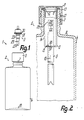
- a discharge device 1 As shown in FIGS. 1 to 4, a discharge device 1 according to the invention has a storage or receiving container 2 for all media components to be mixed and a discharge pump 3 in the form of a hand-operated push piston pump which is held outside the container 2 before mixing and discharge of the components on, which is connected to the container 2 for mixing the components and for discharging the mixed components according to FIG. 3.
- a discharge pump 3 in the form of a hand-operated push piston pump which is held outside the container 2 before mixing and discharge of the components on, which is connected to the container 2 for mixing the components and for discharging the mixed components according to FIG. 3.
- the container 2 has, as a bottle-shaped outer container, a main chamber 4, into which an admixing chamber 5 integrated with a riser pipe 6 is inserted as an inner, substantially smaller-volume container.
- the admixing chamber 5 is substantially smaller than the main chamber 4 both in terms of its cross sections and in terms of its length or height.
- the main chamber 4 has a sleeve-shaped holder 7 on its upper end wall 9, the inside width of which is considerably smaller than the inside width the rest of the main chamber 4 and which only projects outwards beyond the end wall 9.
- This holder 7 is formed in one piece in the manner of a vessel neck with all the other walls of the main chamber 4 and also forms the filling opening for filling the main chamber 4 with the main component.
- the essentially constant internal width of the holder 7 over its length is only slightly larger than the outer circumferential width of the admixture mer 5, which has approximately constant cross sections over its entire height and engages with a small gap distance in the holder 7 such that its inner end protrudes inward beyond the end wall 9, but a large or its largest part is within the holder 7.
- the admixing chamber 5 is thus connected to the main chamber 4 in the manner of a simple plug-in connection and is centered relative to the holder 7 in its position which is axially identical to the central axis l0 of the discharge device l.
- the admixing chamber 5 has a flange ring 11 projecting over its outer circumference, which has the same outer cross section as the associated end of the holder 7 and bears against the end face 12 thereof with an intermediate ring seal 13. Adjacent to the flange ring II, the admixing chamber 5 has a section which is widened in the outside width for centering relative to the holder 7.
- the bottom wall l5 of the cup-shaped admixing chamber 5, which is open at its outer end to its full width, is formed in one piece with the jacket wall l4 of the admixing chamber 5 and with the riser pipe 6, which has constant cross sections over its entire length.
- a longitudinal section of the riser tube 6 projecting into the admixing chamber 5 is shorter than the admixing chamber 5, so that the end of this longitudinal section is provided between the wall 15 and the open end of the admixing chamber 5.
- the other longitudinal section protrudes from the bottom wall l5 into the main chamber 4, but is in the state according to FIG. 2 from its opposite bottom wall l6 a relatively large distance.
- a closure part l7 which forms at least a central part of the bottom wall l5 and projects with the part of the bottom wall or the jacket wall l4 adjoining its outer circumference, projects in a ring collar over the outer circumference of the riser tube 6 a predetermined breaking point l8 is connected in one piece.
- the predetermined breaking point 18 formed by a considerable weakening of the thickness of the wall of the admixing chamber 5 is closed by at least one ring around the central axis 10 Notch groove defined on the inside or on the outside of the associated wall of the admixing chamber 5, such notches 19, 20 being substantially congruent and of the same cross-section or the same depth being provided on both sides in the exemplary embodiment shown.
- the predetermined breaking point 18 can also have a width which is at least approximated to the inner width of the admixing chamber 5.
- the outside width of the riser pipe 6, in particular of its part projecting into the admixing chamber 5, is considerably smaller than the inside width of the admixing chamber 5, for example only about half as large.
- the closure cap 8 engages over the holder 7 on the outside and is secured in its closed position relative to the holder 7 by suitable securing members.
- the securing members 2l are formed by an external thread on the holder 7 and an internal thread on the jacket of the closure cap 8.
- they can also be formed by the members of a snap lock, a spring lock or by a separate securing member that can only be removed by destruction and serves as a seal.
- the flat end wall of the closure cap 8 lies in a sealed manner on the flange ring 11 and presses it against the holder 7, so that the main chamber 4 and the admixing chamber 5 are closed to one another by the closure cap 8 and each individual chamber is closed to the outside on the other hand.
- the admixing chamber 5 is open at its top, the admixing chamber 5 being able to be filled with the associated admixing component only over part or almost its entire height.
- the main chamber 4 remains closed to the outside, ie the admixing chamber 5 is also closed in relation to the main chamber 4 in this state.
- a pipe closure 22 which in the Riser pipe 6 is provided within the admixing chamber 5, namely relatively close to the associated end of the riser pipe 6.
- the disk-shaped or membrane-shaped pipe closure 22 is formed in one piece with the riser pipe 6 and connects to the boundary of its inner channel via an annular predetermined breaking point 23.
- the pipe closure 22 lies within a connection 25 provided for the plug-in connection with an intake port 27 of the discharge pump 3, which is formed by the associated end of the riser pipe 6 designed as a plug-in outer sleeve 26.
- the outer end section of this outer sleeve 26 has a slightly larger inner width than the remaining riser pipe 6 and the outer circumference of the intake manifold 27, this section passing over an intermediate section 28 tapering in the shape of a truncated cone into the subsequent, narrower inner channel 24 and the pipe closure 22 at the transition between the intermediate section 28 and the remaining inner channel 24.
- the length of the further end portion of the outer sleeve 26 is of the order of about half the length of the intake manifold 27, so that it can engage approximately half its length in the adjoining inner channel 24, the internal cross section of which is adapted to the external cross section of the intake manifold 27 that this engages sealed.
- the discharge pump 3 is inserted into the admixing chamber 5 in such a way that the suction nozzle 27 dips into the outer sleeve 26. After striking the end face of the intake manifold 27 on the pipe closure 22, this is broken open by further insertion of the discharge pump 3, so that the intake manifold 27 completely penetrates into the riser pipe 6 into its operating position according to FIG. 3.
- the discharge pump 3 strikes with an end stop 29 on the associated forehead Surface of the riser pipe 6, this end stop 29 being formed by a frustoconical annular shoulder 29 adjoining the intake manifold 27, which, by engaging in the inner edge of the outer sleeve 26, contributes to further sealing the connection between discharge pump 3 and riser pipe 6.
- the discharge pump 3 has not yet reached its operating position in relation to the container 2, in which it has an annular flange 30 projecting beyond the outside of its housing, which is expediently formed by an outer cylinder cover cap of the housing, with the interposition of an annular seal 3l on the outer End face of the flange ring 11 abuts and thereby closes the admixing chamber 5.
- the discharge pump 3 is pressed further into the admixing chamber 5, taking the riser pipe 6 connected to it in a clamped manner via the end stop 29, breaking the predetermined breaking point 18.
- the closure part 17 is completely released from the admixing chamber 5, so that an annular transition opening 32 from the admixing chamber 5 to the main chamber 4 is exposed around the riser pipe 6.
- the admixing component located in the admixing chamber 5 flows automatically into the main chamber 4, in which it is brought together with the main component located there and mixed if necessary by shaking. This mixing is further promoted by the admixing chamber 5 projecting into the main chamber 4 and the ring-shaped closure part 17, since these parts contribute to the swirling of the flow.
- a closure cap 8 replacing sleeve, which is expediently secured by the same securing members 2l of the holder 7 as the closure cap 8, that is, in the exemplary embodiment shown is designed as a screw sleeve 8 'with which the discharge pump 3 can be securely clamped.
- the discharge pump 3 is designed in the exemplary embodiment shown as a thrust piston pump, the cylinder housing of which projects into the admixing chamber 5 and is reduced in the outer diameter several times over the entire length of the admixing chamber 5.
- the discharge pump 3 has a piston unit 34 which can be displaced in the cylinder housing 33 and has an elastic piston sleeve 35 which is formed in one piece at its outer end with an elastically resilient compression sleeve 36.
- the piston sleeve 35 and the compression sleeve 36 are arranged on the outer circumference of a piston tappet 37 which is penetrated by a discharge channel 38 leading to its end located outside the pump housing.
- the piston sleeve 35 forms the outer, annular valve closing part of an outlet valve 39, the valve seat of which is provided on the piston tappet 37.
- the piston sleeve 35 including the valve closing part, can be moved against the direction of the pump stroke, with the compression sleeve 36 springing back against the piston tappet 37, as a result of which the outlet valve 39 opens. This movement can take place either towards the end of the pump stroke by abutment of the piston sleeve 35 on an inner shoulder of the cylinder housing 33 or, depending on the pressure, through a corresponding excess pressure in the pump chamber.
- the discharge pump 3 has an inlet valve 40 in the form of a ball valve, which closes when there is excess pressure in the pump chamber, that is to say during the pumping stroke.
Landscapes
- Engineering & Computer Science (AREA)
- Mechanical Engineering (AREA)
- Chemical & Material Sciences (AREA)
- Dispersion Chemistry (AREA)
- Closures For Containers (AREA)
- Nozzles (AREA)
Applications Claiming Priority (2)
| Application Number | Priority Date | Filing Date | Title |
|---|---|---|---|
| DE19863611690 DE3611690A1 (de) | 1986-04-08 | 1986-04-08 | Austragvorrichtung fuer mischmedien |
| DE3611690 | 1986-04-08 |
Publications (3)
| Publication Number | Publication Date |
|---|---|
| EP0240817A2 true EP0240817A2 (fr) | 1987-10-14 |
| EP0240817A3 EP0240817A3 (en) | 1988-06-29 |
| EP0240817B1 EP0240817B1 (fr) | 1991-09-11 |
Family
ID=6298167
Family Applications (1)
| Application Number | Title | Priority Date | Filing Date |
|---|---|---|---|
| EP87104211A Expired - Lifetime EP0240817B1 (fr) | 1986-04-08 | 1987-03-21 | Distributeur de mélanges |
Country Status (3)
| Country | Link |
|---|---|
| US (1) | US4821923A (fr) |
| EP (1) | EP0240817B1 (fr) |
| DE (2) | DE3611690A1 (fr) |
Cited By (5)
| Publication number | Priority date | Publication date | Assignee | Title |
|---|---|---|---|---|
| EP0606672A1 (fr) * | 1992-12-09 | 1994-07-20 | Bernardino Parise | Récipient pour substances concentrées sous forme de poudre ou de liquide à mettre en solution dans un réceptacle au moment de l'emploi |
| FR2704530A1 (fr) * | 1993-04-26 | 1994-11-04 | Reboul Smt | Valve pour conditionnement aérosol à prise de gaz additionnel amont. |
| EP2092985A1 (fr) | 2008-02-25 | 2009-08-26 | Seriplast | Flacon comprenant un tube plongeur |
| WO2022089994A1 (fr) * | 2020-10-28 | 2022-05-05 | Unilever Ip Holdings B.V. | Récipient de distribution et procédé de fabrication d'un récipient |
| WO2022089956A1 (fr) * | 2020-10-28 | 2022-05-05 | Unilever Ip Holdings B.V. | Récipient de distribution et procédé de fabrication d'un récipient |
Families Citing this family (133)
| Publication number | Priority date | Publication date | Assignee | Title |
|---|---|---|---|---|
| ES2013413A6 (es) * | 1989-03-29 | 1990-05-01 | Monturas Sa | Bomba dispensadora de fluido contenido en un recipiente. |
| IT1232115B (it) * | 1989-06-23 | 1992-01-23 | Veglia Borletti Srl | Dispositivo rilevatore del livello del carburante in un serbatoio di un veicolo |
| US5009342A (en) * | 1989-08-14 | 1991-04-23 | Mark R. Miller | Dual liquid spraying assembly |
| US5273189A (en) * | 1991-02-14 | 1993-12-28 | Societe Technique De Pulverisation - Step | Device for spraying or dispensing a fluid, the device including a member sliding in its admission duct |
| US5252064A (en) * | 1991-02-19 | 1993-10-12 | Teledyne Industries, Inc. | Subgingival irrigator |
| US5246142A (en) * | 1991-09-26 | 1993-09-21 | Dipalma Elio | Device for storing two products separately and subsequently mixing them |
| US5620113A (en) * | 1992-05-22 | 1997-04-15 | Meshberg; Philip | Dispenser and method of its use |
| US5310089A (en) * | 1993-03-22 | 1994-05-10 | Hudgins Richard G | Liquid dispensing system |
| DE4342680A1 (de) * | 1993-12-15 | 1995-06-22 | Pfeiffer Erich Gmbh & Co Kg | Austragvorrichtung für Medien |
| USD366144S (en) | 1994-09-14 | 1996-01-16 | Alves Antonio D | Chalk line holster |
| US5590815A (en) * | 1995-07-13 | 1997-01-07 | Monturas S.A. | Minature pump sprayer |
| GB9525414D0 (en) * | 1995-12-13 | 1996-02-14 | Rocep Lusol Holdings | A device for releasing a fluid into a liquid in a container |
| US5657910A (en) * | 1996-03-25 | 1997-08-19 | Keyser; Robert O. | Safety seal for spray dispensing container |
| DE19615422A1 (de) * | 1996-04-19 | 1997-11-20 | Boehringer Ingelheim Kg | Zweikammer-Kartusche für treibgasfreie Dosieraerosole |
| DE19742559C2 (de) * | 1997-09-26 | 1999-08-05 | Gaplast Gmbh | Behälter mit Pumpe |
| US6003566A (en) * | 1998-02-26 | 1999-12-21 | Becton Dickinson And Company | Vial transferset and method |
| DE19847968A1 (de) * | 1998-10-17 | 2000-04-20 | Boehringer Ingelheim Pharma | Verschlußkappe und Behälter als Zweikammer-Kartusche für Vernebler zur Erzeugung von Aerosolen |
| DE19933330A1 (de) * | 1999-07-16 | 2001-01-18 | Pfeiffer Erich Gmbh & Co Kg | Spender für Medien |
| FR2800360B1 (fr) | 1999-10-29 | 2002-01-18 | Valois Sa | Distributeur de melange de produit extemporane |
| US6769631B2 (en) | 2000-09-08 | 2004-08-03 | Fresh Products, Inc. | Combination air freshener and hand lotion dispenser |
| US6598762B2 (en) * | 2001-01-31 | 2003-07-29 | Affinity Management Solutions, Inc. | Coating touch up kit |
| US6742677B2 (en) * | 2002-04-18 | 2004-06-01 | Valois S.A.S. | Fluid dispenser pump |
| US7147468B2 (en) | 2002-12-31 | 2006-12-12 | Water Pik, Inc. | Hand held oral irrigator |
| US20040245144A1 (en) * | 2003-06-03 | 2004-12-09 | Hurst William E. | Preformed mixing bag for dry powder, apparatus, method and system for using same |
| US20040245124A1 (en) * | 2003-06-03 | 2004-12-09 | Hurst William E. | Preformed mixing bag for dry powder, apparatus, method and system for using same |
| US20050133544A1 (en) * | 2003-12-23 | 2005-06-23 | Tadlock Charles C. | Functional dip tube for cosmetic dispensers |
| USD530010S1 (en) | 2004-03-17 | 2006-10-10 | Water Pik, Inc. | Base for an oral implement |
| US7331486B2 (en) * | 2004-04-06 | 2008-02-19 | Colgate-Palmolive Company | Pump dispenser and cartridge |
| US8074846B2 (en) * | 2004-08-11 | 2011-12-13 | Tekni-Plex, Inc. | Dispenser or vial pump and a tube and valve assembly used in such |
| US7581662B2 (en) * | 2004-12-21 | 2009-09-01 | Michael Powell | Multi-compartment spray dispenser with common pressurizer |
| USD574952S1 (en) | 2006-02-24 | 2008-08-12 | Water Pik, Inc. | Water jet handle |
| USD565175S1 (en) | 2006-02-24 | 2008-03-25 | Water Pik, Inc. | Water jet base |
| US20070203439A1 (en) | 2006-02-24 | 2007-08-30 | Water Pik, Inc. | Water jet unit and handle |
| US7670141B2 (en) | 2006-07-07 | 2010-03-02 | Water Pik, Inc. | Oral irrigator |
| US20080169316A1 (en) * | 2007-01-12 | 2008-07-17 | Ganiere Jeffrey R | Tube with pressurized spring-like action and vacuum lock regulator for rendering optimum liquid extraction and uninterrupted on-command vertical and horizontal operation and a method for retrofitting a liquid dispensing device with such tube |
| USD802120S1 (en) | 2007-02-27 | 2017-11-07 | Water Pik, Inc. | Tip for oral irrigator |
| EP2077132A1 (fr) | 2008-01-02 | 2009-07-08 | Boehringer Ingelheim Pharma GmbH & Co. KG | Dispositif distributeur, dispositif de stockage et procédé pour la distribution d'une formulation |
| US8302816B2 (en) * | 2008-10-15 | 2012-11-06 | Sim Jae K | Spray bottle with refill cartridge |
| US8528784B2 (en) * | 2008-10-15 | 2013-09-10 | Jae K. Sim | Spray bottle with refill cartridge |
| US20100190132A1 (en) | 2009-01-28 | 2010-07-29 | Water Pik, Inc. | Oral irrigator tip |
| US10258442B2 (en) | 2009-03-20 | 2019-04-16 | Water Pik, Inc. | Oral irrigator appliance with radiant energy delivery for bactericidal effect |
| EP2414560B1 (fr) | 2009-03-31 | 2013-10-23 | Boehringer Ingelheim International GmbH | Procédé de revêtement d'une surface d'un composant |
| JP5763053B2 (ja) | 2009-05-18 | 2015-08-12 | ベーリンガー インゲルハイム インターナショナル ゲゼルシャフト ミット ベシュレンクテル ハフツング | アダプタ、吸入器具及びアトマイザ |
| WO2011064163A1 (fr) | 2009-11-25 | 2011-06-03 | Boehringer Ingelheim International Gmbh | Nébuliseur |
| US10016568B2 (en) | 2009-11-25 | 2018-07-10 | Boehringer Ingelheim International Gmbh | Nebulizer |
| BR112012012475B1 (pt) | 2009-11-25 | 2020-03-03 | Boehringer Ingelheim International Gmbh | Nebulizador |
| US9061096B2 (en) | 2009-12-16 | 2015-06-23 | Water Pik, Inc. | Powered irrigator for sinus cavity rinse |
| USD629884S1 (en) | 2009-12-16 | 2010-12-28 | Water Pik, Inc. | Powered irrigator for sinus cavity rinse |
| WO2011160932A1 (fr) | 2010-06-24 | 2011-12-29 | Boehringer Ingelheim International Gmbh | Nébuliseur |
| USD670373S1 (en) | 2010-12-16 | 2012-11-06 | Water Pik, Inc. | Powered irrigator for sinus cavity rinse |
| EP2694220B1 (fr) | 2011-04-01 | 2020-05-06 | Boehringer Ingelheim International GmbH | Appareil médical pourvu d'un récipient |
| US9827384B2 (en) | 2011-05-23 | 2017-11-28 | Boehringer Ingelheim International Gmbh | Nebulizer |
| US9463560B2 (en) * | 2011-10-03 | 2016-10-11 | Illinois Tool Works Inc. | Portable pressurized power source for fastener driving tool |
| WO2013152894A1 (fr) | 2012-04-13 | 2013-10-17 | Boehringer Ingelheim International Gmbh | Pulvérisateur comprenant des moyens de détrompage |
| USD707350S1 (en) | 2012-10-11 | 2014-06-17 | Water Pik, Inc. | Handheld water flosser |
| WO2014059362A2 (fr) | 2012-10-11 | 2014-04-17 | Water Pik, Inc. | Dispositif de nettoyage interdentaire utilisant une alimentation en eau |
| USD714929S1 (en) | 2013-03-14 | 2014-10-07 | Water Pik, Inc. | Base for water flosser |
| USD717427S1 (en) | 2013-03-14 | 2014-11-11 | Water Pik, Inc. | Handle for water flosser |
| USD788907S1 (en) | 2013-03-14 | 2017-06-06 | Water Pik, Inc. | Water flosser base unit with reservoir lid |
| US9642677B2 (en) | 2013-03-14 | 2017-05-09 | Water Pik, Inc. | Oral irrigator with massage mode |
| USD725770S1 (en) | 2013-03-14 | 2015-03-31 | Water Pik, Inc. | Reservoir for water flosser |
| DE202013006898U1 (de) * | 2013-07-31 | 2013-08-20 | Optipharma Gmbh | Arzneimittelflasche |
| JP6643231B2 (ja) | 2013-08-09 | 2020-02-12 | ベーリンガー インゲルハイム インターナショナル ゲゼルシャフト ミット ベシュレンクテル ハフツング | ネブライザ |
| ES2836977T3 (es) | 2013-08-09 | 2021-06-28 | Boehringer Ingelheim Int | Nebulizador |
| US9980793B2 (en) | 2013-11-27 | 2018-05-29 | Water Pik, Inc. | Oral hygiene system |
| CN109350282B (zh) | 2013-11-27 | 2022-03-08 | 洁碧有限公司 | 具有滑动暂停开关的口腔冲洗器 |
| CN105764814B (zh) * | 2013-11-29 | 2019-02-19 | 株式会社大造 | 内容物收容容器、使用其的内容物收容制品、排出制品及排出装置 |
| CN203693808U (zh) | 2013-12-12 | 2014-07-09 | 洁碧有限公司 | 牙科用喷水器 |
| US10085729B2 (en) | 2014-03-06 | 2018-10-02 | Ethicon, Inc. | Methods and devices for forming biomedical coatings using variable mixing ratios of multi-part compositions |
| WO2015169430A1 (fr) | 2014-05-07 | 2015-11-12 | Boehringer Ingelheim International Gmbh | Nébuliseur |
| CN116036425A (zh) | 2014-05-07 | 2023-05-02 | 勃林格殷格翰国际有限公司 | 喷雾器、指示器装置及容器 |
| IL247927B (en) | 2014-05-07 | 2022-09-01 | Boehringer Ingelheim Int | Container, a device that turns a liquid into a fine spray and use |
| EP2957347B1 (fr) | 2014-06-18 | 2017-02-22 | Albea Thomaston Inc. | Système permettant de distribuer un mélange d'un premier produit et d'un deuxième produit |
| USD772397S1 (en) | 2014-12-01 | 2016-11-22 | Water Pik, Inc. | Oral irrigator with a charging device |
| USD772396S1 (en) | 2014-12-01 | 2016-11-22 | Water Pik, Inc. | Handheld oral irrigator |
| CN205586102U (zh) | 2014-12-01 | 2016-09-21 | 洁碧有限公司 | 防水无线口腔冲洗器 |
| WO2016175449A1 (fr) * | 2015-04-30 | 2016-11-03 | 주식회사 삼화플라스틱 | Dispositif d'étanchéité de récipient de liquide |
| USD780908S1 (en) | 2015-11-03 | 2017-03-07 | Water Pik, Inc. | Handheld oral irrigator |
| USD822196S1 (en) | 2016-01-14 | 2018-07-03 | Water Pik, Inc. | Oral irrigator |
| USD782656S1 (en) | 2016-01-25 | 2017-03-28 | Water Pik, Inc. | Oral irrigator |
| USD786422S1 (en) | 2016-01-25 | 2017-05-09 | Water Pik, Inc. | Oral irrigator |
| USD802747S1 (en) | 2016-07-19 | 2017-11-14 | Water Pik, Inc. | Reservoir for oral irrigator |
| USD819956S1 (en) | 2016-01-25 | 2018-06-12 | Water Pik, Inc. | Kit bag |
| USD796028S1 (en) | 2016-07-19 | 2017-08-29 | Water Pik, Inc. | Oral irrigator |
| US10835356B2 (en) | 2016-01-25 | 2020-11-17 | Water Pik, Inc. | Swivel assembly for oral irrigator handle |
| CN114732549A (zh) | 2016-01-25 | 2022-07-12 | 洁碧有限公司 | 减小形状因子的口腔冲洗器 |
| USD804018S1 (en) | 2016-07-19 | 2017-11-28 | Water Pik, Inc. | Base for an oral irrigator |
| USD794773S1 (en) | 2016-07-19 | 2017-08-15 | Water Pik, Inc. | Oral irrigator |
| USD783809S1 (en) | 2016-01-25 | 2017-04-11 | Water Pik, Inc. | Oral irrigator handle |
| USD804016S1 (en) | 2016-02-05 | 2017-11-28 | Water Pik, Inc. | Handheld oral irrigator |
| USD809650S1 (en) | 2016-02-22 | 2018-02-06 | Water Pik, Inc. | Oral irrigator |
| USD783810S1 (en) | 2016-02-22 | 2017-04-11 | Water Pik, Inc. | Handle for an oral irrigator |
| USD782657S1 (en) | 2016-03-02 | 2017-03-28 | Water Pik, Inc. | Oral irrigator handle |
| USD802119S1 (en) | 2016-03-02 | 2017-11-07 | Water Pik, Inc. | Oral irrigator |
| KR102397188B1 (ko) | 2016-03-02 | 2022-05-12 | 워터 피크 인코포레이티드 | 구강 세정기용 작동 조립체 |
| USD809651S1 (en) | 2016-07-19 | 2018-02-06 | Water Pik, Inc. | Combination base and reservoir for an oral irrigator |
| USD807822S1 (en) | 2016-07-19 | 2018-01-16 | Water Pik, Inc. | Power supply cartridge |
| CA3120435C (fr) | 2016-12-15 | 2024-04-09 | Water Pik, Inc. | Ensembles pivot et clapet de pause pour manche d'irrigateur buccal |
| USD833000S1 (en) | 2016-12-15 | 2018-11-06 | Water Pik, Inc. | Oral irrigator unit |
| USD839409S1 (en) | 2016-12-15 | 2019-01-29 | Water Pik, Inc. | Oral irrigator unit |
| USD832420S1 (en) | 2016-12-15 | 2018-10-30 | Water Pik, Inc. | Oral irrigator base |
| USD832419S1 (en) | 2016-12-15 | 2018-10-30 | Water Pik, Inc. | Oral irrigator unit |
| USD867579S1 (en) | 2016-12-15 | 2019-11-19 | Water Pik, Inc. | Oral irrigator unit |
| USD825741S1 (en) | 2016-12-15 | 2018-08-14 | Water Pik, Inc. | Oral irrigator handle |
| USD840023S1 (en) | 2016-12-15 | 2019-02-05 | Water Pik, Inc. | Oral irrigator reservoir |
| USD832418S1 (en) | 2016-12-15 | 2018-10-30 | Water Pik, Inc. | Oral irrigator base |
| USD840022S1 (en) | 2016-12-15 | 2019-02-05 | Water Pik, Inc. | Oral irrigator handle |
| USD833600S1 (en) | 2016-12-15 | 2018-11-13 | Water Pik, Inc. | Oral irrigator reservoir |
| USD829886S1 (en) | 2016-12-15 | 2018-10-02 | Water Pik, Inc. | Oral irrigator base |
| EP3554419B1 (fr) | 2016-12-15 | 2022-12-07 | Water Pik, Inc. | Irrigateur buccal à fixation magnétique |
| USD822826S1 (en) | 2016-12-15 | 2018-07-10 | Water Pik, Inc. | Oral irrigator base |
| USD822825S1 (en) | 2016-12-15 | 2018-07-10 | Water Pik, Inc. | Oral irrigator unit |
| USD834180S1 (en) | 2016-12-15 | 2018-11-20 | Water Pik, Inc. | Oral irrigator base |
| USD833601S1 (en) | 2017-02-06 | 2018-11-13 | Water Pik, Inc. | Oral irrigator |
| USD833602S1 (en) | 2017-02-06 | 2018-11-13 | Water Pik, Inc. | Oral irrigator base |
| USD829887S1 (en) | 2017-02-06 | 2018-10-02 | Water Pik, Inc. | Oral irrigator reservoir |
| CN111315665B (zh) * | 2017-11-24 | 2025-01-10 | 雀巢产品有限公司 | 用于饮料容器的附接件 |
| USD868243S1 (en) | 2018-03-16 | 2019-11-26 | Water Pik, Inc. | Oral irrigator tip |
| USD877324S1 (en) | 2018-05-17 | 2020-03-03 | Water Pik, Inc. | Oral irrigator handle |
| USD912794S1 (en) | 2018-08-01 | 2021-03-09 | Fresh Products, Inc. | Air freshener |
| USD900291S1 (en) | 2018-08-06 | 2020-10-27 | Fresh Products, Inc. | Air freshener |
| USD888936S1 (en) | 2019-02-22 | 2020-06-30 | Water Pik, Inc. | Cordless water flosser |
| USD889636S1 (en) | 2019-02-22 | 2020-07-07 | Water Pik, Inc. | Water flosser |
| JP7614618B2 (ja) * | 2019-06-14 | 2025-01-16 | 株式会社ダイゾー | 吐出装置 |
| CN114007756B (zh) * | 2019-06-14 | 2023-08-22 | 株式会社大造 | 排出装置 |
| DE102019129821B4 (de) * | 2019-11-05 | 2022-01-05 | Langmatz Gmbh | Dichtungskappe |
| US11161675B2 (en) * | 2020-02-14 | 2021-11-02 | Callington Haven Pty Ltd. | Solution mixing and dispensing container system having a cartridge release mechanism |
| US12458722B1 (en) | 2020-02-27 | 2025-11-04 | Fresh Products, Inc. | Systems, method, and devices for dispensing volatile liquids |
| US11097297B1 (en) * | 2020-05-25 | 2021-08-24 | Silgan Dispensing Systems Thomaston Corporation | Large tube cover for plunger tube |
| USD966498S1 (en) | 2020-09-15 | 2022-10-11 | Water Pik, Inc. | Oral irrigator |
| USD1016274S1 (en) | 2021-02-16 | 2024-02-27 | Water Pik, Inc. | Oral irrigator |
| US11772111B1 (en) | 2022-09-16 | 2023-10-03 | Branded AcquiCo No 5, LLC | Dispenser |
| USD1060046S1 (en) | 2022-10-03 | 2025-02-04 | Branded AcquiCo No 5, LLC | Dispenser |
Family Cites Families (15)
| Publication number | Priority date | Publication date | Assignee | Title |
|---|---|---|---|---|
| US2829801A (en) * | 1955-06-22 | 1958-04-08 | Oil Equipment Lab Inc | Rupturable closure for pressurized containers |
| US3240403A (en) * | 1960-04-28 | 1966-03-15 | Modern Lab Inc | Pressurized dispensing device |
| US3134505A (en) * | 1960-04-28 | 1964-05-26 | Modern Lab Inc | Pressurized dispensing device |
| DE1486405A1 (de) * | 1965-04-15 | 1969-06-04 | H V Hardman Company Inc | Vorrichtung zum Mischen und Abgeben von Materialien |
| DE1617825C3 (de) * | 1966-03-03 | 1974-11-28 | Hans Schwarzkopf Gmbh, 2000 Hamburg | Vorrichtung zum Mischen und Versprühen einer aus wenigstens zwei flüssigen, pulverförmigen oder pastenförmigen Bestandteilen und einem Treibgas bestehenden Mischung |
| US3355238A (en) * | 1966-08-31 | 1967-11-28 | Schwartzman Gilbert | Mixing assembly for brush-headed applicator |
| US3441177A (en) * | 1967-01-30 | 1969-04-29 | Scovill Manufacturing Co | One-shot valve assembly for aerosol container |
| DE1939086C3 (de) * | 1969-07-31 | 1975-01-09 | Wolf Geraete Gmbh | Behälter zur Aufbewahrung und zum Ansetzen einer mindestens eine zu lösende Komponente enthaltenden Flüssigkeit |
| US3648899A (en) * | 1969-09-11 | 1972-03-14 | Heinz Lukesch | Method and apparatus for dyeing hair |
| US3655096A (en) * | 1969-10-22 | 1972-04-11 | Pillsbury Co | Container for diluting and dispensing material |
| IT996631B (it) * | 1973-08-31 | 1975-12-10 | Guala R E Sas | Dispositivo di chiusura per flaco ni e simili provvisto di sigillo di garanzia ed incorporante un con tenitore perforabile per sostanze da immettere nel flacone |
| US4201316A (en) * | 1975-04-25 | 1980-05-06 | Colgate-Palmolive Company | Capsule having frangible wall portion |
| US3966089A (en) * | 1975-04-25 | 1976-06-29 | Colgate-Palmolive Company | Diluting and dispensing container |
| US4019512A (en) * | 1975-12-04 | 1977-04-26 | Tenczar Francis J | Adhesively activated sterile connector |
| US4676775A (en) * | 1984-06-27 | 1987-06-30 | David M. Roxe | Fluid administration apparatus and method |
-
1986
- 1986-04-08 DE DE19863611690 patent/DE3611690A1/de not_active Withdrawn
-
1987
- 1987-03-21 EP EP87104211A patent/EP0240817B1/fr not_active Expired - Lifetime
- 1987-03-21 DE DE8787104211T patent/DE3772807D1/de not_active Expired - Lifetime
- 1987-10-07 US US07/105,884 patent/US4821923A/en not_active Expired - Lifetime
Cited By (6)
| Publication number | Priority date | Publication date | Assignee | Title |
|---|---|---|---|---|
| EP0606672A1 (fr) * | 1992-12-09 | 1994-07-20 | Bernardino Parise | Récipient pour substances concentrées sous forme de poudre ou de liquide à mettre en solution dans un réceptacle au moment de l'emploi |
| FR2704530A1 (fr) * | 1993-04-26 | 1994-11-04 | Reboul Smt | Valve pour conditionnement aérosol à prise de gaz additionnel amont. |
| EP2092985A1 (fr) | 2008-02-25 | 2009-08-26 | Seriplast | Flacon comprenant un tube plongeur |
| FR2927888A1 (fr) * | 2008-02-25 | 2009-08-28 | Seriplast Soc Par Actions Simp | Flacon comprenant un tube plongeur |
| WO2022089994A1 (fr) * | 2020-10-28 | 2022-05-05 | Unilever Ip Holdings B.V. | Récipient de distribution et procédé de fabrication d'un récipient |
| WO2022089956A1 (fr) * | 2020-10-28 | 2022-05-05 | Unilever Ip Holdings B.V. | Récipient de distribution et procédé de fabrication d'un récipient |
Also Published As
| Publication number | Publication date |
|---|---|
| EP0240817A3 (en) | 1988-06-29 |
| DE3772807D1 (de) | 1991-10-17 |
| US4821923A (en) | 1989-04-18 |
| EP0240817B1 (fr) | 1991-09-11 |
| DE3611690A1 (de) | 1987-10-15 |
Similar Documents
| Publication | Publication Date | Title |
|---|---|---|
| EP0240817B1 (fr) | Distributeur de mélanges | |
| EP0922499B1 (fr) | Distributeur de fluides | |
| EP0243667B1 (fr) | Distributeur pour médiums | |
| DE69803361T2 (de) | Vorrichtung zur abgabe vom fliessfähigen produkt mit verschlussvorrichtung | |
| EP1027165B1 (fr) | Procede permettant de distribuer au moins deux produits differents et distributeur a cet effet | |
| DE3631341C2 (de) | Zerstäuber für fließfähige Medien | |
| EP0680768B1 (fr) | Distributeur de substances | |
| EP0775530B1 (fr) | Distributeur avec deux unitées à débiter | |
| EP0193054B1 (fr) | Distributeur de substances susceptibles de couler | |
| DE3425478C2 (fr) | ||
| EP0810164B1 (fr) | Appareil pour la préparation d'un mélange d'un ingrédient actif et d'un diluant et procédé pour remplir une cartouche utilisée dans un tel appareil | |
| DE2223471C3 (de) | Ventil zum Einsatz in einen Behälter, insbesondere in einen Aerosol-Behälter | |
| EP1108439B1 (fr) | Distributeur de produit | |
| DE4412041A1 (de) | Austragvorrichtung für fließfähige Medien, insbesondere für den Austrag in nur einem Hub | |
| EP2605858A1 (fr) | Module de distribution et procédé pour remplir un module de distribution | |
| EP0761314B1 (fr) | Appareil distributeur de fluides | |
| EP0504748A1 (fr) | Distributeur de fluids | |
| EP0516635B1 (fr) | Distributeur de milieux | |
| EP0829307B1 (fr) | Distributeur de fluides | |
| DE4005529A1 (de) | Austragkopf fuer medien | |
| DE10258140B4 (de) | System zum Befüllen von Applikationsbehältern | |
| DE3545409C2 (de) | Austragvorrichtung für fließfähige Medien | |
| EP4334041B1 (fr) | Distributeur de gouettes, distributeur de liquide et procédé de fabrication d'un distributeur de liquide | |
| DE19723134A1 (de) | Austragvorrichtung für Medien | |
| DE3347843A1 (de) | Mehrkomponenten-kartusche |
Legal Events
| Date | Code | Title | Description |
|---|---|---|---|
| PUAI | Public reference made under article 153(3) epc to a published international application that has entered the european phase |
Free format text: ORIGINAL CODE: 0009012 |
|
| AK | Designated contracting states |
Kind code of ref document: A2 Designated state(s): CH DE FR GB IT LI |
|
| PUAL | Search report despatched |
Free format text: ORIGINAL CODE: 0009013 |
|
| RHK1 | Main classification (correction) |
Ipc: B65D 47/34 |
|
| AK | Designated contracting states |
Kind code of ref document: A3 Designated state(s): CH DE FR GB IT LI |
|
| 17P | Request for examination filed |
Effective date: 19880913 |
|
| 17Q | First examination report despatched |
Effective date: 19900502 |
|
| RAP1 | Party data changed (applicant data changed or rights of an application transferred) |
Owner name: ING. ERICH PFEIFFER GMBH & CO. KG |
|
| GRAA | (expected) grant |
Free format text: ORIGINAL CODE: 0009210 |
|
| AK | Designated contracting states |
Kind code of ref document: B1 Designated state(s): CH DE FR GB IT LI |
|
| REF | Corresponds to: |
Ref document number: 3772807 Country of ref document: DE Date of ref document: 19911017 |
|
| GBT | Gb: translation of ep patent filed (gb section 77(6)(a)/1977) | ||
| ITF | It: translation for a ep patent filed | ||
| ET | Fr: translation filed | ||
| PLBE | No opposition filed within time limit |
Free format text: ORIGINAL CODE: 0009261 |
|
| STAA | Information on the status of an ep patent application or granted ep patent |
Free format text: STATUS: NO OPPOSITION FILED WITHIN TIME LIMIT |
|
| 26N | No opposition filed | ||
| REG | Reference to a national code |
Ref country code: GB Ref legal event code: IF02 |
|
| PGFP | Annual fee paid to national office [announced via postgrant information from national office to epo] |
Ref country code: GB Payment date: 20020225 Year of fee payment: 16 |
|
| PGFP | Annual fee paid to national office [announced via postgrant information from national office to epo] |
Ref country code: FR Payment date: 20020318 Year of fee payment: 16 |
|
| PGFP | Annual fee paid to national office [announced via postgrant information from national office to epo] |
Ref country code: CH Payment date: 20020325 Year of fee payment: 16 |
|
| PGFP | Annual fee paid to national office [announced via postgrant information from national office to epo] |
Ref country code: DE Payment date: 20020522 Year of fee payment: 16 |
|
| PG25 | Lapsed in a contracting state [announced via postgrant information from national office to epo] |
Ref country code: GB Free format text: LAPSE BECAUSE OF NON-PAYMENT OF DUE FEES Effective date: 20030321 |
|
| PG25 | Lapsed in a contracting state [announced via postgrant information from national office to epo] |
Ref country code: LI Free format text: LAPSE BECAUSE OF NON-PAYMENT OF DUE FEES Effective date: 20030331 Ref country code: CH Free format text: LAPSE BECAUSE OF NON-PAYMENT OF DUE FEES Effective date: 20030331 |
|
| PG25 | Lapsed in a contracting state [announced via postgrant information from national office to epo] |
Ref country code: DE Free format text: LAPSE BECAUSE OF NON-PAYMENT OF DUE FEES Effective date: 20031001 |
|
| GBPC | Gb: european patent ceased through non-payment of renewal fee |
Effective date: 20030321 |
|
| REG | Reference to a national code |
Ref country code: CH Ref legal event code: PL |
|
| PG25 | Lapsed in a contracting state [announced via postgrant information from national office to epo] |
Ref country code: FR Free format text: LAPSE BECAUSE OF NON-PAYMENT OF DUE FEES Effective date: 20031127 |
|
| REG | Reference to a national code |
Ref country code: FR Ref legal event code: ST |
|
| PG25 | Lapsed in a contracting state [announced via postgrant information from national office to epo] |
Ref country code: IT Free format text: LAPSE BECAUSE OF NON-PAYMENT OF DUE FEES;WARNING: LAPSES OF ITALIAN PATENTS WITH EFFECTIVE DATE BEFORE 2007 MAY HAVE OCCURRED AT ANY TIME BEFORE 2007. THE CORRECT EFFECTIVE DATE MAY BE DIFFERENT FROM THE ONE RECORDED. Effective date: 20050321 |