EP0356711A2 - Procédé et dispositif d'ajustage de la chrominance - Google Patents
Procédé et dispositif d'ajustage de la chrominance Download PDFInfo
- Publication number
- EP0356711A2 EP0356711A2 EP89113906A EP89113906A EP0356711A2 EP 0356711 A2 EP0356711 A2 EP 0356711A2 EP 89113906 A EP89113906 A EP 89113906A EP 89113906 A EP89113906 A EP 89113906A EP 0356711 A2 EP0356711 A2 EP 0356711A2
- Authority
- EP
- European Patent Office
- Prior art keywords
- chroma
- color difference
- signal
- signals
- difference signal
- Prior art date
- Legal status (The legal status is an assumption and is not a legal conclusion. Google has not performed a legal analysis and makes no representation as to the accuracy of the status listed.)
- Granted
Links
Images

Classifications
-
- H—ELECTRICITY
- H04—ELECTRIC COMMUNICATION TECHNIQUE
- H04N—PICTORIAL COMMUNICATION, e.g. TELEVISION
- H04N23/00—Cameras or camera modules comprising electronic image sensors; Control thereof
- H04N23/80—Camera processing pipelines; Components thereof
- H04N23/84—Camera processing pipelines; Components thereof for processing colour signals
- H04N23/88—Camera processing pipelines; Components thereof for processing colour signals for colour balance, e.g. white-balance circuits or colour temperature control
-
- H—ELECTRICITY
- H04—ELECTRIC COMMUNICATION TECHNIQUE
- H04N—PICTORIAL COMMUNICATION, e.g. TELEVISION
- H04N23/00—Cameras or camera modules comprising electronic image sensors; Control thereof
- H04N23/80—Camera processing pipelines; Components thereof
- H04N23/84—Camera processing pipelines; Components thereof for processing colour signals
- H04N23/85—Camera processing pipelines; Components thereof for processing colour signals for matrixing
-
- H—ELECTRICITY
- H04—ELECTRIC COMMUNICATION TECHNIQUE
- H04N—PICTORIAL COMMUNICATION, e.g. TELEVISION
- H04N23/00—Cameras or camera modules comprising electronic image sensors; Control thereof
- H04N23/80—Camera processing pipelines; Components thereof
- H04N23/84—Camera processing pipelines; Components thereof for processing colour signals
- H04N23/86—Camera processing pipelines; Components thereof for processing colour signals for controlling the colour saturation of colour signals, e.g. automatic chroma control circuits
Definitions
- the present invention relates to method and apparatus for adjusting chroma and, in particular, to such method and apparatus which can be applied when white balance is automatically adjusted by an internal light measurement system.
- an automatic white balance adjusting method includes an external light measurement system and an internal light measurement system.
- the external light measurement system color temperatures are measured by an external sensor and the control signal that are obtained from such measurement are used to control the gains of red and blue signals.
- the internal light measurement system is a control system which is based on a general fact that averaging of colors on the entire screen colored provides a grey color (that is, even when a general object is photographed, if the colors are averaged over the entire screen, then there is provided a color which is equivalent to that obtained when a white object is photographed).
- the internal light measurement system is a control system based on a premise that colors in a screen are often distributed equally on the positive and negative sides of axes, (R - Y) and (B - Y).
- color signals (E R - E Y ) and (E B - E Y ) are respectively integrated over the entire screen and the gains of red and blue signal are adjusted or controlled so that the resultant integration average value can coincide with a reference level showing predetermined grey color.
- the present invention aims at eliminating the drawback found in the above-mentioned conventional internal light measurement type of automatic white balance adjusting method.
- a chroma adjusting method which can be applied to an automatic white balance adjusting method to control the gains of red and blue signals in accordance with signals obtained by photographing an object, in which chroma information corresponding to the ratio of high-chroma colors in the entire screen is obtained in accordance with the signals obtained by photographing the object, and the gains of chroma signals are controlled in such a manner that the gains of the chroma signals are increased as the chroma information is decreased.
- chroma information which corresponds to the ratio of high-chroma colors included in the entire screen.
- the chroma information is low in the shade and under dark illumination.
- the gains of chroma signals are adjusted in accordance with the chroma information. That is, the gains of the chroma signals are controlled such that the gains of the chroma signals are increased as the chroma information is decreased, and when there are many low-chroma colors, chroma levels are to be raised.
- FIG. 1 there is shown a circuit diagram of a camera including a chroma adjusting device according to the invention.
- Fig. 1 light entering through a lens 10 is converted through an image pickup element 12 to red, green and blue signals (E R , E G , E B ).
- the signals (E R , E G , E B ) are respectively input through amplifiers 14, 16 and 18 to a matrix circuit 20, in which they are converted to a brightness signal E Y , and color difference signals (E R - E Y ), (E B - E Y ).
- the amplifiers 14 and 18 are controlled in gain, whereby an automatic white balance adjustment can be performed.
- the brightness signal E Y , and the color difference signals (E R - E Y ), (E B - E Y ) are respectively applied to an encoder 26.
- a synchronization signal (SYNC) is added to the brightness signal E Y by an adder 26F.
- the color difference signals (E R - E Y ) and (E B - E Y ) are respectively input to modulators 26A and 26B to each of which a color sub-carrier wave of 3.58 MHZ is applied, in which the color difference signals are respectively two-phase modulated.
- the thus modulated signals are added together in an adder 26C to provide a chroma signal, which is then transmitted through an amplifier 26D to an adder 26I.
- a burst signal is added to the chroma signal to provide a color signal E C .
- the amplifier 26D as will be described later, is controlled in gain, thereby performing a chroma adjustment.
- the brightness signal E Y and the color signal E C are added together in an adder 26E and the resultant signal is output as a video signal in the NTSC system.
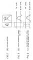
- a color difference signal (E R - E Y ) shown in Fig. 2(B) has been obtained from a picture including a strong red color as shown in Fig. 2(A). If the color difference signal is integrated over the entire screen, then the integration average value thereof is moved nearer to the red than a black level and, in this state, if an automatic white balance adjustment is performed, then the color of the face of a man shown in Fig. 2(A) is mis-controlled toward the complementary colors (cyanogen, blue) of red.
- a certain level (which is referred to as a threshold level) is set, and a strong color difference signal which exceeds the threshold level is then blanked to a black level (a DC value to be pedestal clamped, that is, a reference level), as shown in Fig. 2(C). Due to this, the strong color difference signal is removed from the color difference signal of the original picture so that the average value thereof can be made to come near to a grey color.
- the color difference signal (E R - E Y ) that is output from the matrix circuit 20 is applied to the contact 44A of a blanking switch 44 and is also applied to a strong color difference signal detection part 40A which is used to detect a high-chroma color (that is, a strong color difference signal).
- the strong color difference signal detection part 40A is composed of an upper threshold level setting means 41A for a color difference signal (E R - E Y ), a lower threshold level setting means 41B for a color difference signal (E R - E Y ), comparators 42A, 42B, and a NAND circuit 43.
- the upper and lower threshold level setting means 41A and 41B which are respectively used to set upper and lower threshold levels for blanking the strong color difference signals respectively on the red side and the cyanogen side of the color difference signal (E R - E Y ), respectively output the upper and lower threshold levels.
- the comparator 42A There are applied to the positive and negative inputs of the comparator 42A the upper threshold level and the color difference signal (E R - E Y ), respectively.
- the comparator 42A compares these two input signals with each other and, when the color difference signal (E R - E Y ) is found smaller than the upper threshold level, the comparator 42A outputs an H level signal, while it outputs a strong color difference detection signal (that is, an L level signal) when the color difference signal (E R - E Y ) is found larger than the upper threshold level.
- a strong color difference detection signal that is, an L level signal
- the positive and negative inputs of the comparator 42B there are applied to the positive and negative inputs of the comparator 42B the color difference signal (E R - E Y ) and the lower threshold level, respectively.
- the comparator 42B compares these two input signals with each other and, when the color difference (E R - E Y ) is greater than the lower threshold level, the comparator 42B outputs an H level signal, while it outputs a strong color difference detection signal (an L level signal) when the color difference signal (E R - E Y ) is smaller than the lower threshold level.
- the NAND circuit 43 outputs an L level signal when both of signals input thereto from the comparators 42A, 42B are H level signals, that is, when the color difference signal (E R - E Y ) is present between the upper and lower threshold levels, while it outputs an H level signal when at least one of the two input signals is the L level signal, that is, when the color difference signal (E R - E Y ) goes beyond or below the upper threshold level or the lower threshold level (namely, when a strong color difference signal is present).
- a blanking switch 44 comprises an input contact 44A for inputting the color difference signal (E R - E Y ), an input contact 44B for inputting a reference level from a reference level setting means 36, and a movable contact piece 44C which can be selectively connected to these two input contacts 44A and 44B.
- the blanking switch 44 When an L level signal is input therein from the NAND circuit 43, the blanking switch 44 then connects the movable contact piece 44C to the contact 44A to thereby output the strong color difference signal (E R - E Y ) to an integrating circuit 28 and, when an H level signal is input therein from the NAND circuit 43, the switch 44 then connects the movable contact piece 44C to the contact 44B to thereby output the reference level to the integrating circuit 28.
- the color difference signal (E B - E Y ) that is output from the matrix circuit 20 is applied to a contact 48A of a blanking switch 48 and is also applied to a strong color difference signal detection part 40B which is used to detect a color difference signal.
- the strong color difference signal detection part 40B is constructed similarly to the above-mentioned strong color difference signal detection part 40A.
- An upper threshold level setting means 45A and a lower threshold level setting means 45B, respectively included in the strong color difference signal detection part 40B, are adapted to set upper and lower threshold levels which are respectively used to blank the strong color difference signals on the blue color side and the yellow color side of the color difference signal (E B - E Y ), respectively.
- comparators 46A, 46B and a NAND circuit 47 are further included in the part 40B. However, they are adapted to operate similarly to the before-described comparators 42A, 42B and NAND circuit 43 and thus the detailed description thereof is omitted here.
- a blanking switch 48 comprises an input contact 48A for inputting the color difference signal (E B - E Y ), an input contact 48B for inputting a reference level from reference level setting means 38, and a movable contact piece 48C which can be selectively connected to these input contacts 48A and 48B.
- the blanking switch 48 When an L level signal is input therein from the NAND circuit 47, the blanking switch 48 then connects the movable contact piece 48C to the contact 48A to thereby output the color difference signal (E B - E Y ) to an integrating circuit 30 and, when an H level signal is input therein from the NAND circuit 43, then it connects the movable contact piece 48C to the contact 48B to thereby output a reference level to the integrating circuit 30.
- the integrating circuits 28 and 30 integrate the color difference signals (E R - E Y ) and (E B - E Y ), respectively. However, if the color difference signals are strong color difference signals which go beyond or below the predetermined upper or lower threshold levels, the integrating circuits 28 and 30 blank the strong color difference signals and after then integrate the thus blanked signals (in particular, the reference levels in place of the strong color difference signals), and input the integration average values to differential amplifiers 32 and 34, respectively.
- the differential amplifier 32 outputs to the amplifier 14 a gain control signal R CONT , which can be obtained by amplifying the difference between the above two input signals, to thereby control the gain of a signal E R to be amplified by the amplifier 14.
- the differential amplifier 34 output to the amplifier 18 a gain control signal B CONT , which can be obtained by amplifying the difference between the above two input signals, to thereby the gain of a signal E B to be amplified by the amplifier 18.
- the signals E R and E B are controlled so that the average values of the color difference signals (E R - E Y ) and (E B - E Y ) on the entire screen can be made to coincide with their associated reference levels. Also, even when an original picture includes in part a strong color, by taking an average of colors in the picture with the strong color being removed, the average value can be made to approach to a grey color, so that a proper white balance adjustment can be made without being influenced by the strong color.
- the output signals of the strong color difference signal detection parts 40A and 40B (which provide the H level signals when the strong color difference signal is detected) are respectively applied through an OR circuit 50 to an integrating circuit 52.
- the integrating circuit 52 integrates the input signals and outputs the chroma information that corresponds to the integration value thereof, that is, corresponds to the ratio of the H level signal (a high-chroma color) in one screen (one frame).
- This chroma information consists of an analog signal having a level existing between the L level and the H level and it increases as the high-chroma colors in one screen are increased.
- the chroma information is amplified by a linear or non-linear amplifier 54 and is then output to the amplifier 26D which is used to amplify a chroma signal.
- the amplifier 26D is composed of a variable gain amplifier the gain of which can be varied continuously or stepwise by the chroma information input therein through the amplifier 54, that is, the gain thereof is controlled in such a manner that is provides a normal level when the chroma information is large, while, for the small chroma information, the chroma level can be increased.
- the signals (blanking information) that are output from the strong color difference detection parts 40A, 40B of the automatic white balance adjusting apparatus are used.
- this is not always limitative, but any other information can be used, provided that the information represents whether a color is a high-chroma color or not.
- the automatic white balance adjusting method is not always limited to the illustrated embodiment, but any of an internal light measurement type will be all right.
- the gain can be controlled so as to increase the level of a chroma signal, a good color reproduction can be realized even in the shade or under the dark illumination where chroma is low, and, in particular, the above effect can be expected when white balance is adjusted by means of an internal light measurement system.
Landscapes
- Engineering & Computer Science (AREA)
- Multimedia (AREA)
- Signal Processing (AREA)
- Processing Of Color Television Signals (AREA)
Applications Claiming Priority (2)
| Application Number | Priority Date | Filing Date | Title |
|---|---|---|---|
| JP63216105A JPH0263394A (ja) | 1988-08-30 | 1988-08-30 | 彩度調整方法及び装置 |
| JP216105/88 | 1988-08-30 |
Publications (3)
| Publication Number | Publication Date |
|---|---|
| EP0356711A2 true EP0356711A2 (fr) | 1990-03-07 |
| EP0356711A3 EP0356711A3 (fr) | 1992-07-08 |
| EP0356711B1 EP0356711B1 (fr) | 1995-10-04 |
Family
ID=16683322
Family Applications (1)
| Application Number | Title | Priority Date | Filing Date |
|---|---|---|---|
| EP89113906A Expired - Lifetime EP0356711B1 (fr) | 1988-08-30 | 1989-07-27 | Procédé et dispositif d'ajustage de la chrominance |
Country Status (5)
| Country | Link |
|---|---|
| US (1) | US5010393A (fr) |
| EP (1) | EP0356711B1 (fr) |
| JP (1) | JPH0263394A (fr) |
| KR (1) | KR960008992B1 (fr) |
| DE (1) | DE68924459T2 (fr) |
Families Citing this family (7)
| Publication number | Priority date | Publication date | Assignee | Title |
|---|---|---|---|---|
| US5153713A (en) * | 1986-02-21 | 1992-10-06 | Canon Kabushiki Kaisha | Color temperature information forming device |
| US5255077A (en) * | 1989-09-29 | 1993-10-19 | Canon Kabushiki Kaisha | White balance control based upon magnitude of flicker |
| US5589879A (en) | 1993-03-26 | 1996-12-31 | Fuji Photo Film Co., Ltd. | Performing white balance correction on integrated divided areas of which average color is substantially white |
| US7123293B1 (en) * | 1998-01-07 | 2006-10-17 | Fuji Photo Film Co., Ltd. | Image processing method to compensate for color differences due to a type of image sensing device |
| US20040123961A1 (en) * | 1998-10-19 | 2004-07-01 | Huang Sunny En Liung | Collapsible auto shade |
| KR100350789B1 (ko) | 1999-03-04 | 2002-08-28 | 엘지전자 주식회사 | 이미지 검색시스템의 분위기 칼라 자동추출 및 원래 칼라 조정방법 |
| US7190394B2 (en) | 2002-06-04 | 2007-03-13 | Micron Technology, Inc. | Method for statistical analysis of images for automatic white balance of color channel gains for image sensors |
Family Cites Families (11)
| Publication number | Priority date | Publication date | Assignee | Title |
|---|---|---|---|---|
| JPS5919515B2 (ja) * | 1978-03-07 | 1984-05-07 | ソニー株式会社 | ホワイトバランス調整回路 |
| JPS59123387A (ja) * | 1982-12-29 | 1984-07-17 | Canon Inc | 撮像装置 |
| JPS61269484A (ja) * | 1985-05-24 | 1986-11-28 | Fuji Photo Film Co Ltd | カラ−ビデオカメラの自動ホワイトバランス調整装置 |
| US4814861A (en) * | 1985-07-10 | 1989-03-21 | Canon Kabushiki Kaisha | Signal processing apparatus with independent gain control for chrominance and color signals |
| US4739393A (en) * | 1985-11-05 | 1988-04-19 | Sanyo Electric Co., Ltd. | Circuit for performing white balance correction using two color temperature sensors |
| US4739392A (en) * | 1986-01-07 | 1988-04-19 | Victor Company Of Japan, Ltd. | White balance adjusting apparatus having a plurality of standard color references automatically selected by the detected color temperature |
| JP2618908B2 (ja) * | 1987-08-13 | 1997-06-11 | 富士写真フイルム株式会社 | 自動白バランス調整方法及び装置 |
| US4883360A (en) * | 1987-08-13 | 1989-11-28 | Fuji Photo Film Co., Ltd. | Method and apparatus for automatically adjusting white balance |
| JPH0817497B2 (ja) * | 1987-08-27 | 1996-02-21 | キヤノン株式会社 | 自動ホワイト・バランス補正装置 |
| JPH0787588B2 (ja) * | 1987-12-29 | 1995-09-20 | 富士写真フイルム株式会社 | 自動白バランス調整方法及び装置 |
| JPH0828877B2 (ja) * | 1988-07-18 | 1996-03-21 | 富士写真フイルム株式会社 | 自動白バランス調整方法及び装置 |
-
1988
- 1988-08-30 JP JP63216105A patent/JPH0263394A/ja active Pending
-
1989
- 1989-07-27 EP EP89113906A patent/EP0356711B1/fr not_active Expired - Lifetime
- 1989-07-27 DE DE68924459T patent/DE68924459T2/de not_active Expired - Lifetime
- 1989-07-27 US US07/385,449 patent/US5010393A/en not_active Expired - Lifetime
- 1989-08-11 KR KR1019890011463A patent/KR960008992B1/ko not_active Expired - Lifetime
Also Published As
| Publication number | Publication date |
|---|---|
| JPH0263394A (ja) | 1990-03-02 |
| EP0356711B1 (fr) | 1995-10-04 |
| EP0356711A3 (fr) | 1992-07-08 |
| US5010393A (en) | 1991-04-23 |
| KR960008992B1 (ko) | 1996-07-10 |
| DE68924459D1 (de) | 1995-11-09 |
| DE68924459T2 (de) | 1996-03-07 |
| KR900016794A (ko) | 1990-11-14 |
Similar Documents
| Publication | Publication Date | Title |
|---|---|---|
| US4922330A (en) | Method and apparatus for automatically adjusting white balance | |
| US4883360A (en) | Method and apparatus for automatically adjusting white balance | |
| US4954884A (en) | Method and apparatus for automatically adjusting white balance | |
| US4931856A (en) | Image sensing apparatus | |
| US5644359A (en) | Image input apparatus having a white balance correction means and a method of inputting an image using the image input apparatus | |
| US5045928A (en) | White balance control with choice of control dependent on brightness | |
| US4635101A (en) | Image conversion apparatus for television signals | |
| EP0356711B1 (fr) | Procédé et dispositif d'ajustage de la chrominance | |
| JP2618908B2 (ja) | 自動白バランス調整方法及び装置 | |
| JP2618909B2 (ja) | 自動白バランス調整方法及び装置 | |
| US5272521A (en) | White balance control based upon negative or positive mode selection | |
| JPH04142895A (ja) | ビデオカメラ複合ホワイトバランス切換装置 | |
| JP3733641B2 (ja) | 色信号処理回路 | |
| JP2512665Y2 (ja) | ビデオカメラのオ−トホワイトバランス回路 | |
| JPH074019B2 (ja) | 自動白バランス調整方法及び装置 | |
| JP3000576B2 (ja) | 撮像装置 | |
| JP3434086B2 (ja) | オートホワイトバランス補正装置及び補正方法 | |
| JPS62265885A (ja) | オ−トホワイトバランス調整回路 | |
| JPH0229191A (ja) | 撮像装置 | |
| JPS63115489A (ja) | オ−トホワイトバランス制御回路 | |
| JPS61150489A (ja) | カラ−ビデオカメラ | |
| JPS61136397A (ja) | ビデオカメラの信号処理方式 | |
| JPH04107082A (ja) | ネガ画像信号の処理回路 | |
| JPS63234690A (ja) | 撮像装置 | |
| JPH05130636A (ja) | オ−トホワイトバランス回路 |
Legal Events
| Date | Code | Title | Description |
|---|---|---|---|
| PUAI | Public reference made under article 153(3) epc to a published international application that has entered the european phase |
Free format text: ORIGINAL CODE: 0009012 |
|
| AK | Designated contracting states |
Kind code of ref document: A2 Designated state(s): DE FR GB |
|
| PUAL | Search report despatched |
Free format text: ORIGINAL CODE: 0009013 |
|
| AK | Designated contracting states |
Kind code of ref document: A3 Designated state(s): DE FR GB |
|
| 17P | Request for examination filed |
Effective date: 19920831 |
|
| 17Q | First examination report despatched |
Effective date: 19940516 |
|
| GRAA | (expected) grant |
Free format text: ORIGINAL CODE: 0009210 |
|
| AK | Designated contracting states |
Kind code of ref document: B1 Designated state(s): DE FR GB |
|
| REF | Corresponds to: |
Ref document number: 68924459 Country of ref document: DE Date of ref document: 19951109 |
|
| ET | Fr: translation filed | ||
| PLBE | No opposition filed within time limit |
Free format text: ORIGINAL CODE: 0009261 |
|
| STAA | Information on the status of an ep patent application or granted ep patent |
Free format text: STATUS: NO OPPOSITION FILED WITHIN TIME LIMIT |
|
| 26N | No opposition filed | ||
| REG | Reference to a national code |
Ref country code: GB Ref legal event code: IF02 |
|
| REG | Reference to a national code |
Ref country code: GB Ref legal event code: 732E |
|
| REG | Reference to a national code |
Ref country code: FR Ref legal event code: CD Ref country code: FR Ref legal event code: TP |
|
| PGFP | Annual fee paid to national office [announced via postgrant information from national office to epo] |
Ref country code: DE Payment date: 20080807 Year of fee payment: 20 |
|
| PGFP | Annual fee paid to national office [announced via postgrant information from national office to epo] |
Ref country code: FR Payment date: 20080718 Year of fee payment: 20 |
|
| PGFP | Annual fee paid to national office [announced via postgrant information from national office to epo] |
Ref country code: GB Payment date: 20080806 Year of fee payment: 20 |
|
| REG | Reference to a national code |
Ref country code: GB Ref legal event code: PE20 Expiry date: 20090726 |
|
| PG25 | Lapsed in a contracting state [announced via postgrant information from national office to epo] |
Ref country code: GB Free format text: LAPSE BECAUSE OF EXPIRATION OF PROTECTION Effective date: 20090726 |