EP0356798B1 - Transmission à courroie et poulie - Google Patents
Transmission à courroie et poulie Download PDFInfo
- Publication number
- EP0356798B1 EP0356798B1 EP89114982A EP89114982A EP0356798B1 EP 0356798 B1 EP0356798 B1 EP 0356798B1 EP 89114982 A EP89114982 A EP 89114982A EP 89114982 A EP89114982 A EP 89114982A EP 0356798 B1 EP0356798 B1 EP 0356798B1
- Authority
- EP
- European Patent Office
- Prior art keywords
- belt
- pulley
- flat
- flat belt
- width
- Prior art date
- Legal status (The legal status is an assumption and is not a legal conclusion. Google has not performed a legal analysis and makes no representation as to the accuracy of the status listed.)
- Expired - Lifetime
Links
- 230000005540 biological transmission Effects 0.000 title claims description 51
- 230000002093 peripheral effect Effects 0.000 claims description 8
- 238000010586 diagram Methods 0.000 description 3
- 238000009826 distribution Methods 0.000 description 3
- 238000010276 construction Methods 0.000 description 2
- 230000000694 effects Effects 0.000 description 2
- 238000010008 shearing Methods 0.000 description 2
- 230000006378 damage Effects 0.000 description 1
- 230000001419 dependent effect Effects 0.000 description 1
- 238000009828 non-uniform distribution Methods 0.000 description 1
- 239000011347 resin Substances 0.000 description 1
- 229920005989 resin Polymers 0.000 description 1
Images



Classifications
-
- F—MECHANICAL ENGINEERING; LIGHTING; HEATING; WEAPONS; BLASTING
- F16—ENGINEERING ELEMENTS AND UNITS; GENERAL MEASURES FOR PRODUCING AND MAINTAINING EFFECTIVE FUNCTIONING OF MACHINES OR INSTALLATIONS; THERMAL INSULATION IN GENERAL
- F16H—GEARING
- F16H55/00—Elements with teeth or friction surfaces for conveying motion; Worms, pulleys or sheaves for gearing mechanisms
- F16H55/32—Friction members
- F16H55/36—Pulleys
- F16H55/38—Means or measures for increasing adhesion
-
- F—MECHANICAL ENGINEERING; LIGHTING; HEATING; WEAPONS; BLASTING
- F16—ENGINEERING ELEMENTS AND UNITS; GENERAL MEASURES FOR PRODUCING AND MAINTAINING EFFECTIVE FUNCTIONING OF MACHINES OR INSTALLATIONS; THERMAL INSULATION IN GENERAL
- F16H—GEARING
- F16H7/00—Gearings for conveying rotary motion by endless flexible members
- F16H7/02—Gearings for conveying rotary motion by endless flexible members with belts; with V-belts
Definitions
- the present invention relates to a flat belt and pulley transmission comprising two spaced flat pulleys and a single flat belt reeved around these flat pulleys.
- Such transmissions may comprise either a single flat belt which, as also shown in Fig. 14, co-operates with a crown which is formed on the outer periphery of each pulley.
- Such transmissions may comprise a flat belt the belt body of which has a plurality of embedded endless cores and is provided with at least one separating cut that extends between two adjacent cores in the longitudinal direction of the belt whereby, as also shown in Fig.
- such a separating cut is aligned with a part of each pulley other than each of at least two crowns that are provided on the outer periphery of the pulleys and spaced in the width direction thereof for respectively co-operating with an adjacent singular belt-part.
- the slip ratio between the pulleys and the belt was 1 % - 3 %.
- a flat belt and pulley transmission comprising two spaced flat pulleys and a single flat belt reeved around these flat pulleys, wherein
- the flat belt and pulley transmission of the present invention provides an increased transmission capacity by an increased contact width of the flat belt with the at least two crowns on the outer periphery of the pulleys. With this increased transmission capacity the transmission of the present invention also provides a much improved belt life primarily due to the strategic position of the at least one groove as related to the at least two crowns on the outer periphery of the pulleys so that with this particular relationship in mind additional advantages may be obtained with the features of the dependent claims 2 to 5.
- Fig. 1 shows a conventional belt transmission A as disclosed for example in FR-A-1 131 923.
- the belt transmission A comprises a flat pulley 1 for transmitting a high load and a flat belt means 4 reeved around the pulley 1.
- the outer periphery of the pulley 1 is a generally cylindrical surface spaced at a uniform distance from the center of rotation (not shown) of the pulley 1 and four crowns 3 are arranged in a row in the width direction of the pulley 1 on this outer periphery. Therefore, the crowns 3 are all at the same distance from the shaft (not shown) on which the pulley is mounted and the crowns 3, have the same width w, height h and radius of curvature R, respectively.
- the flat belt means 4 comprises four belt members 5 separated from each other in the width direction.
- Each of the belt members 5 comprises a belt body 6 and a plurality of cores 7 embedded in the belt body 6 and extending in the longitudinal direction of the belt member.
- the width of each belt member 5 corresponds to the width w of the corresponding crown 3.
- the bearing stress generated in the flat belt means 4 peaks at the centre in the width direction of the respective belt members 5 corresponding to the respective crowns 3 on the pulley 1 as shown in Fig. 2.
- the bearing stress is distributed more evenly in the width direction of the flat belt 4 as the whole than where there is only a single crown and a single flat belt.
- the maximum value ⁇ max of the bearing stress at each crown 3 of the pulley 1 can be controlled even if the overall width of the flat pulley 1 is increased, and the maximum bearing stress in the belt means 4 does not exceed the capacity of any belt member, with the result that transmission capacity can be increased.
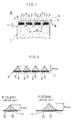
- Fig. 4 shows a a belt transmission according to a first embodiment of the present invention.
- three crowns 3 are provided in the width direction on the outer periphery of the pulley 1.
- the flat belt means 4 comprises a belt body 6 made of rubber and having a plurality of endless cores 7 made of a resin and embedded in parallel to each other in the belt body 6.
- Two grooves 8 with bottoms extending in the longitudinal direction of the bolt are formed at positions corresponding to one-third and two-thirds of the bolt width in the width direction of the belt, the grooves being in the inner peripheral surface of the belt body 6 which is in contact with the pulley 1.
- Each groove 8 extends between adjacent cores 7 and its bottom is nearer to the outer peripheral surface of the belt than the position of the cores 7 as shown in Fig. 5.
- the groove 8 can have a rectangular cross-section and the corners 8b and 8b between its bottom 8a and the side walls thereof are circular arc surfaces. More specifically, for example, in a flat belt 4 having a width of 38.1 mm and a thickness of 3.5 mm and cores 7 embedded at a positions spaced 1.5 mm from the outer peripheral surface, grooves 8 are formed at positions corresponding to one-third and two-thirds of the belt width and in the width direction thereof, which are 1 mm and 2.6 mm in width and depth, respectively.
- the groove 8 can have a V-shaped cross-section and its bottom 8a can be a circular arc surface.
- the groove 8 can be a shallow groove having the bottom nearer to the inner surface of the belt than the position of the cores 7.
- the position of the grooves is between the crowns 3 of the pulley.
- the crown 3 is formed at the position corresponding to a part 6a in the belt body 6 in which no groove 8 is formed.
- the width of the part 6a in the belt body 6 in which the groove 8 is not formed is approximately the same as the width w of the crown 3 of the pulley 1.
- the bearing stress in the flat belt 4 peaks the centers of the parts 6a corresponding to each of the crowns 3 on the pulley 1 as shown in Fig. 7. Therefore, similar to the above described embodiment, the bearing stress is distributed more evenly in the belt width direction across the whole of the width of the flat belt 4, which limits the maximum bearing stress at the crowns 3 of the pulley 1, with the result that the shearing stress of the belt 4 does not exceed its maximum and transmission capacity can be increased.
- Fig. 8 shows a second embodiment of the present invention which is similar to the first embodiment in that grooves 8 are formed in the inner peripheral surface of the flat belt 4, but in this embodiment, three grooves 8 are provided and four crowns 3 are formed in the width direction of the pulley in accordance with the number of the grooves 8. The same effect as that in the above described embodiment is provided in this embodiment.
- Fig. 9 shows a third embodiment of the present invention.
- the outer periphery of the pulley on which crowns 3 are formed is a generally cylindrical surface with the parts spaced at the same distance from the center of rotation of the pulley
- the outer periphery of the pulley 1 in this embodiment is in form of a circular arc such that the center in a width direction is farther from the center of rotation of the pulley than the two sides thereof.
- Three crowns 3 are arranged in a row in the pulley width direction on the outer periphery.
- the construction of the flat belt 4 is the same as in the first embodiment (shown in Fig. 4). In this embodiment, transmission capacity is further improved over the capacity in the first and second embodiments.
- Fig. 10 shows a forth embodiment of the present invention which is similar to the third embodiment, except. that the number of crowns 3 and grooves 8 are four and three, respectively instead of three and two. Otherwise the construction is the same as that in the third embodiment, and the same effect can be achieved.
- a flat belt 4 having grooves 8 in the inner peripheral surface as in the above embodiment can be used with a conventional pulley as shown in Fig. 14. having one crown on the outer periphery.
- the belt 4 is bent along the crown of the pulley because of the grooves, with the result that the contact width of the belt with the pulley can be increased and the transmission capacity can be raised.
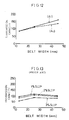
- the crown 3 of the pulley 1 had a radius of 450 mm.
- Each belt 4 was reeved around a pair of spaced flat pulleys 1 and one pulley 1 was rotated at 2600 rpm under a shaft load of 200 kg and the transmission capacity was tested. As a result, the characteristic shown in Fig. 11 was obtained. In addition, the slip ratio between the pulley 1 and the, belt 4 was 2%.
Landscapes
- Engineering & Computer Science (AREA)
- General Engineering & Computer Science (AREA)
- Mechanical Engineering (AREA)
- Pulleys (AREA)
Claims (5)
- Mécanisme de transmission à courroie plate et poulie, comprenant deux poulies plates (1)écartées et une seule courroie plate (4) passée dans ces poulies plates, dans lequel- ladite courroie plate (4) comprend un corps de courroie (6) à une pluralité des âmes continues en retrait (7), qui est prévu d'au moins une rainure (8) qui s'étend entre deux âmes contiguës en sens longitudinal de sa surface intérieure périphérique qui se trouve en contact avec lesdites poulies plates (1), ladite rainure (8) ayant une profondeur telle que son fond (8a) soit plus proche à la surface extérieure périphérique dudit corps de courroie (6) que la position desdites âmes continues (7);- chacune desdites poulies plates (1) présente au moins deux sommets (3) sur sa périphérie extérieure, qui sont y espacés en sens transversal de façon que ladite rainure (8) de ladite courroie plate (4) soit alignée sur une partie de ladite poulie, autre que celle sur laquelle est formé un tel sommet.
- Mécanisme de transmission à courroie plate et poulie selon la revendication 1, dans lequel lesdits sommes (3) de chaque poulie plate (1) sont disposés aux distances égales du centre de rotation de ladite poulie.
- Mécanisme de transmission à courroie plate et poulie selon la revendication 1 ou 2, dans lequel la périphérie extérieur de chaque poulie plate (1) présente, en sens transversal, essentiellement la forme d'un arc cylindrique, et le centre, en sens transversal de chaque poulie, est plus loin du centre de rotation de la poulie que les extrémités de la dernière.
- Mécanisme de transmission à courroie plate et poulie selon la revendication 3, dans lequel ladite rainure (8) de ladite courroie plate (4) a un profil en travers rectangulaire, dont chacun des coins (8b) entre son fond (8a) et ses parois latérales présente la forme d'un arc de cercle.
- Mécanisme de transmission à courroie plate et poulie selon une quelconque des revendications 1 a 3, dans lequel ladite rainure (8) de ladite courroie plate (4) a un profil en travers en V dont le fond (8a) présente la forme d'un arc de cercle.
Applications Claiming Priority (4)
| Application Number | Priority Date | Filing Date | Title |
|---|---|---|---|
| JP107081/88 | 1988-08-12 | ||
| JP107080/88 | 1988-08-12 | ||
| JP1988107080U JPH0649967Y2 (ja) | 1988-08-12 | 1988-08-12 | 高負荷伝動用平プーリ |
| JP1988107081U JPH0714678Y2 (ja) | 1988-08-12 | 1988-08-12 | 高負荷伝動用平ベルト及び該ベルトを用いたベルト伝動機構 |
Publications (2)
| Publication Number | Publication Date |
|---|---|
| EP0356798A1 EP0356798A1 (fr) | 1990-03-07 |
| EP0356798B1 true EP0356798B1 (fr) | 1993-12-29 |
Family
ID=26447148
Family Applications (1)
| Application Number | Title | Priority Date | Filing Date |
|---|---|---|---|
| EP89114982A Expired - Lifetime EP0356798B1 (fr) | 1988-08-12 | 1989-08-11 | Transmission à courroie et poulie |
Country Status (3)
| Country | Link |
|---|---|
| US (1) | US4995855A (fr) |
| EP (1) | EP0356798B1 (fr) |
| DE (1) | DE68911794T2 (fr) |
Families Citing this family (19)
| Publication number | Priority date | Publication date | Assignee | Title |
|---|---|---|---|---|
| JP3083684B2 (ja) * | 1993-06-29 | 2000-09-04 | 富士写真フイルム株式会社 | ベルト伝動機構 |
| US6419208B1 (en) * | 1999-04-01 | 2002-07-16 | Otis Elevator Company | Elevator sheave for use with flat ropes |
| US6742769B2 (en) | 1999-04-01 | 2004-06-01 | Otis Elevator Company | Elevator sheave for use with flat ropes |
| US6672983B2 (en) | 2000-12-21 | 2004-01-06 | The Goodyear Tire & Rubber Company | Power transmission drive system |
| US7670240B2 (en) * | 2001-10-04 | 2010-03-02 | Otis Elevator Company | Elevator belt assembly with noise reducing groove arrangement |
| US8444515B2 (en) * | 2001-11-13 | 2013-05-21 | Otis Elevator Company | Elevator belt assembly with noise and vibration reducing grooveless jacket arrangement |
| WO2003062117A1 (fr) * | 2002-01-16 | 2003-07-31 | Otis Elevator Company | Systeme d'ascenseur comprenant un ensemble courroie avec une configuration de rainures permettant de diminuer les vibrations et le bruit |
| US9248003B2 (en) * | 2002-12-30 | 2016-02-02 | Varian Medical Systems, Inc. | Receiver used in marker localization sensing system and tunable to marker frequency |
| JP3808858B2 (ja) * | 2003-10-07 | 2006-08-16 | 住友ゴム工業株式会社 | サポートリング、及びタイヤ組立体 |
| CN1997581B (zh) * | 2004-08-04 | 2012-05-16 | 奥蒂斯电梯公司 | 升降机系统中采用的滑轮和组件 |
| EP2969877B1 (fr) * | 2013-03-15 | 2020-10-07 | Otis Elevator Company | Poulies à gorge asymétriques et dirigées pour systèmes d'ascenseur à courroies multiples torsadées |
| WO2014192438A1 (fr) * | 2013-05-28 | 2014-12-04 | 京セラドキュメントソリューションズ株式会社 | Courroie métallique et mécanisme de transmission comprenant ladite courroie métallique |
| JP5903412B2 (ja) * | 2013-08-08 | 2016-04-13 | 京セラドキュメントソリューションズ株式会社 | 駆動装置 |
| ES2602062T3 (es) * | 2014-05-19 | 2017-02-17 | Kone Corporation | Un ascensor |
| ES2692202T3 (es) * | 2015-05-20 | 2018-11-30 | Kone Corporation | Ascensor que comprende una disposición de supervisión de cables para detectar un desplazamiento de cables con forma de correa |
| JP7472547B2 (ja) * | 2020-03-03 | 2024-04-23 | 京セラドキュメントソリューションズ株式会社 | 駆動伝達装置及び画像形成装置 |
| CN112228527B (zh) * | 2020-10-15 | 2022-05-17 | 重庆大学 | 一种可变齿厚的齿轮组件 |
| KR102743267B1 (ko) * | 2022-04-27 | 2024-12-18 | 현대엘리베이터주식회사 | 엘리베이터용 시브 |
| KR102743266B1 (ko) * | 2022-04-27 | 2024-12-18 | 현대엘리베이터주식회사 | 엘리베이터용 벨트 |
Family Cites Families (8)
| Publication number | Priority date | Publication date | Assignee | Title |
|---|---|---|---|---|
| GB1051587A (fr) * | 1900-01-01 | |||
| US1356917A (en) * | 1920-02-09 | 1920-10-26 | Hamm William | Belt-pulley |
| FR580601A (fr) * | 1923-07-13 | 1924-11-12 | Perfectionnement aux poulies de transmission | |
| US2054619A (en) * | 1934-02-21 | 1936-09-15 | Dayton Rubber Mfg Co | Belt |
| FR1131923A (fr) * | 1955-04-05 | 1957-03-01 | Perfectionnements aux transmissions pour courroies | |
| JPS50121147A (fr) * | 1974-03-11 | 1975-09-22 | ||
| JPS58189844A (ja) * | 1982-04-30 | 1983-11-05 | Toshiba Corp | 光学式デジタルデイスクプレ−ヤのエラ−検出回路 |
| JPS622514A (ja) * | 1985-06-27 | 1987-01-08 | 信英通信工業株式会社 | 電解コンデンサ |
-
1989
- 1989-08-11 DE DE68911794T patent/DE68911794T2/de not_active Expired - Fee Related
- 1989-08-11 EP EP89114982A patent/EP0356798B1/fr not_active Expired - Lifetime
- 1989-08-11 US US07/392,284 patent/US4995855A/en not_active Expired - Fee Related
Also Published As
| Publication number | Publication date |
|---|---|
| DE68911794D1 (de) | 1994-02-10 |
| DE68911794T2 (de) | 1994-07-07 |
| US4995855A (en) | 1991-02-26 |
| EP0356798A1 (fr) | 1990-03-07 |
Similar Documents
| Publication | Publication Date | Title |
|---|---|---|
| US4995855A (en) | Flat belt transmission | |
| US4571224A (en) | Belt drive system | |
| US4826473A (en) | Belt for a continuously variable transmission | |
| US5704862A (en) | Dual sided poly-V drive belt and pulley therefor | |
| CA1211958A (fr) | Courroie-chaine de transmission | |
| US4011939A (en) | Closed loop cleated belt/grooved pulley conveyor system | |
| JPS6184436A (ja) | チエーンベルト | |
| US4552548A (en) | V-Belt transmission apparatus | |
| EP0183414B1 (fr) | Courroie de transmission à maillons | |
| JPH0219338B2 (fr) | ||
| US5242333A (en) | Rocker-pin type friction gearing chain | |
| US4938737A (en) | Transmission belt | |
| US3988941A (en) | Drive belt | |
| EP0000802A1 (fr) | Courroie de transmission métallique | |
| JP2832412B2 (ja) | チェーンベルト | |
| US4525158A (en) | Belt-pulley drive mechanism | |
| US7201689B2 (en) | Metal driving belt | |
| US4643702A (en) | Driving belt | |
| JPS6340979B2 (fr) | ||
| EP0367321B1 (fr) | Chaîne de transmission pour variateur continu à poulies coniques | |
| JPH0649967Y2 (ja) | 高負荷伝動用平プーリ | |
| US4003269A (en) | Power transmission belt | |
| JPH0714678Y2 (ja) | 高負荷伝動用平ベルト及び該ベルトを用いたベルト伝動機構 | |
| JPH0514028Y2 (fr) | ||
| EP0125757B1 (fr) | Courroie de transmission en V |
Legal Events
| Date | Code | Title | Description |
|---|---|---|---|
| PUAI | Public reference made under article 153(3) epc to a published international application that has entered the european phase |
Free format text: ORIGINAL CODE: 0009012 |
|
| AK | Designated contracting states |
Kind code of ref document: A1 Designated state(s): DE FR GB IT |
|
| 17P | Request for examination filed |
Effective date: 19900731 |
|
| 17Q | First examination report despatched |
Effective date: 19910917 |
|
| GRAA | (expected) grant |
Free format text: ORIGINAL CODE: 0009210 |
|
| AK | Designated contracting states |
Kind code of ref document: B1 Designated state(s): DE FR GB IT |
|
| REF | Corresponds to: |
Ref document number: 68911794 Country of ref document: DE Date of ref document: 19940210 |
|
| ITF | It: translation for a ep patent filed | ||
| ET | Fr: translation filed | ||
| PLBE | No opposition filed within time limit |
Free format text: ORIGINAL CODE: 0009261 |
|
| STAA | Information on the status of an ep patent application or granted ep patent |
Free format text: STATUS: NO OPPOSITION FILED WITHIN TIME LIMIT |
|
| 26N | No opposition filed | ||
| PGFP | Annual fee paid to national office [announced via postgrant information from national office to epo] |
Ref country code: GB Payment date: 19970801 Year of fee payment: 9 |
|
| PGFP | Annual fee paid to national office [announced via postgrant information from national office to epo] |
Ref country code: FR Payment date: 19970802 Year of fee payment: 9 |
|
| PGFP | Annual fee paid to national office [announced via postgrant information from national office to epo] |
Ref country code: DE Payment date: 19971030 Year of fee payment: 9 |
|
| PG25 | Lapsed in a contracting state [announced via postgrant information from national office to epo] |
Ref country code: GB Free format text: LAPSE BECAUSE OF NON-PAYMENT OF DUE FEES Effective date: 19980811 |
|
| GBPC | Gb: european patent ceased through non-payment of renewal fee |
Effective date: 19980811 |
|
| PG25 | Lapsed in a contracting state [announced via postgrant information from national office to epo] |
Ref country code: FR Free format text: LAPSE BECAUSE OF NON-PAYMENT OF DUE FEES Effective date: 19990430 |
|
| PG25 | Lapsed in a contracting state [announced via postgrant information from national office to epo] |
Ref country code: DE Free format text: LAPSE BECAUSE OF NON-PAYMENT OF DUE FEES Effective date: 19990601 |
|
| REG | Reference to a national code |
Ref country code: FR Ref legal event code: ST |
|
| PG25 | Lapsed in a contracting state [announced via postgrant information from national office to epo] |
Ref country code: IT Free format text: LAPSE BECAUSE OF NON-PAYMENT OF DUE FEES;WARNING: LAPSES OF ITALIAN PATENTS WITH EFFECTIVE DATE BEFORE 2007 MAY HAVE OCCURRED AT ANY TIME BEFORE 2007. THE CORRECT EFFECTIVE DATE MAY BE DIFFERENT FROM THE ONE RECORDED. Effective date: 20050811 |