EP0356824B1 - Verfahren und Vorrichtung zum Aufrichten zusammengelegter rohrförmiger Zuschnitte - Google Patents
Verfahren und Vorrichtung zum Aufrichten zusammengelegter rohrförmiger Zuschnitte Download PDFInfo
- Publication number
- EP0356824B1 EP0356824B1 EP89115203A EP89115203A EP0356824B1 EP 0356824 B1 EP0356824 B1 EP 0356824B1 EP 89115203 A EP89115203 A EP 89115203A EP 89115203 A EP89115203 A EP 89115203A EP 0356824 B1 EP0356824 B1 EP 0356824B1
- Authority
- EP
- European Patent Office
- Prior art keywords
- blank
- pair
- pusher
- discharging
- blanks
- Prior art date
- Legal status (The legal status is an assumption and is not a legal conclusion. Google has not performed a legal analysis and makes no representation as to the accuracy of the status listed.)
- Expired - Lifetime
Links
- 238000000034 method Methods 0.000 title claims abstract description 19
- 238000007599 discharging Methods 0.000 claims abstract description 46
- 238000005096 rolling process Methods 0.000 claims abstract description 30
- 238000003825 pressing Methods 0.000 claims description 7
- 238000002407 reforming Methods 0.000 abstract 1
- 238000012856 packing Methods 0.000 description 35
- 210000000078 claw Anatomy 0.000 description 11
- 230000000694 effects Effects 0.000 description 3
- 235000021056 liquid food Nutrition 0.000 description 3
- 239000000463 material Substances 0.000 description 3
- 239000008267 milk Substances 0.000 description 3
- 210000004080 milk Anatomy 0.000 description 3
- 235000013336 milk Nutrition 0.000 description 3
- 230000015572 biosynthetic process Effects 0.000 description 2
- 238000010276 construction Methods 0.000 description 2
- 238000007789 sealing Methods 0.000 description 2
- 239000004698 Polyethylene Substances 0.000 description 1
- 239000005030 aluminium foil Substances 0.000 description 1
- 238000005452 bending Methods 0.000 description 1
- 238000005520 cutting process Methods 0.000 description 1
- 238000010586 diagram Methods 0.000 description 1
- 238000003780 insertion Methods 0.000 description 1
- 230000037431 insertion Effects 0.000 description 1
- 238000005304 joining Methods 0.000 description 1
- 239000007788 liquid Substances 0.000 description 1
- 238000012423 maintenance Methods 0.000 description 1
- 238000004519 manufacturing process Methods 0.000 description 1
- 238000012986 modification Methods 0.000 description 1
- 230000004048 modification Effects 0.000 description 1
- -1 polyethylene Polymers 0.000 description 1
- 229920000573 polyethylene Polymers 0.000 description 1
- 239000012858 resilient material Substances 0.000 description 1
- 238000003860 storage Methods 0.000 description 1
- 229920001169 thermoplastic Polymers 0.000 description 1
- 239000004416 thermosoftening plastic Substances 0.000 description 1
- 238000012546 transfer Methods 0.000 description 1
Images


Classifications
-
- B—PERFORMING OPERATIONS; TRANSPORTING
- B65—CONVEYING; PACKING; STORING; HANDLING THIN OR FILAMENTARY MATERIAL
- B65B—MACHINES, APPARATUS OR DEVICES FOR, OR METHODS OF, PACKAGING ARTICLES OR MATERIALS; UNPACKING
- B65B43/00—Forming, feeding, opening or setting-up containers or receptacles in association with packaging
- B65B43/26—Opening or distending bags; Opening, erecting, or setting-up boxes, cartons, or carton blanks
- B65B43/32—Opening or distending bags; Opening, erecting, or setting-up boxes, cartons, or carton blanks by external pressure diagonally applied
- B65B43/325—Opening or distending bags; Opening, erecting, or setting-up boxes, cartons, or carton blanks by external pressure diagonally applied to boxes, cartons or carton blanks
-
- B—PERFORMING OPERATIONS; TRANSPORTING
- B31—MAKING ARTICLES OF PAPER, CARDBOARD OR MATERIAL WORKED IN A MANNER ANALOGOUS TO PAPER; WORKING PAPER, CARDBOARD OR MATERIAL WORKED IN A MANNER ANALOGOUS TO PAPER
- B31B—MAKING CONTAINERS OF PAPER, CARDBOARD OR MATERIAL WORKED IN A MANNER ANALOGOUS TO PAPER
- B31B2100/00—Rigid or semi-rigid containers made by folding single-piece sheets, blanks or webs
-
- B—PERFORMING OPERATIONS; TRANSPORTING
- B31—MAKING ARTICLES OF PAPER, CARDBOARD OR MATERIAL WORKED IN A MANNER ANALOGOUS TO PAPER; WORKING PAPER, CARDBOARD OR MATERIAL WORKED IN A MANNER ANALOGOUS TO PAPER
- B31B—MAKING CONTAINERS OF PAPER, CARDBOARD OR MATERIAL WORKED IN A MANNER ANALOGOUS TO PAPER
- B31B2120/00—Construction of rigid or semi-rigid containers
- B31B2120/30—Construction of rigid or semi-rigid containers collapsible; temporarily collapsed during manufacturing
-
- B—PERFORMING OPERATIONS; TRANSPORTING
- B31—MAKING ARTICLES OF PAPER, CARDBOARD OR MATERIAL WORKED IN A MANNER ANALOGOUS TO PAPER; WORKING PAPER, CARDBOARD OR MATERIAL WORKED IN A MANNER ANALOGOUS TO PAPER
- B31B—MAKING CONTAINERS OF PAPER, CARDBOARD OR MATERIAL WORKED IN A MANNER ANALOGOUS TO PAPER
- B31B50/00—Making rigid or semi-rigid containers, e.g. boxes or cartons
- B31B50/002—Prebreaking
-
- B—PERFORMING OPERATIONS; TRANSPORTING
- B31—MAKING ARTICLES OF PAPER, CARDBOARD OR MATERIAL WORKED IN A MANNER ANALOGOUS TO PAPER; WORKING PAPER, CARDBOARD OR MATERIAL WORKED IN A MANNER ANALOGOUS TO PAPER
- B31B—MAKING CONTAINERS OF PAPER, CARDBOARD OR MATERIAL WORKED IN A MANNER ANALOGOUS TO PAPER
- B31B50/00—Making rigid or semi-rigid containers, e.g. boxes or cartons
- B31B50/02—Feeding or positioning sheets, blanks or webs
- B31B50/022—Holders for feeding or positioning blanks or webs
- B31B50/024—Rotating holders, e.g. star wheels, drums
-
- B—PERFORMING OPERATIONS; TRANSPORTING
- B31—MAKING ARTICLES OF PAPER, CARDBOARD OR MATERIAL WORKED IN A MANNER ANALOGOUS TO PAPER; WORKING PAPER, CARDBOARD OR MATERIAL WORKED IN A MANNER ANALOGOUS TO PAPER
- B31B—MAKING CONTAINERS OF PAPER, CARDBOARD OR MATERIAL WORKED IN A MANNER ANALOGOUS TO PAPER
- B31B50/00—Making rigid or semi-rigid containers, e.g. boxes or cartons
- B31B50/74—Auxiliary operations
- B31B50/76—Opening and distending flattened articles
- B31B50/78—Mechanically
Definitions
- This invention relates to a method and a device for raising flattened tubular blanks to form rectangular tubular parallelepipeds.
- various paper containers are made to fit for various purposes, e.g., disposable type of packing containers for containing liquid foods such as milk.
- These packing containers are supplied in the form of rimpled and flattened parallelepipedic packing container blanks, getting their bottoms closed by an automatic packing machine, and being formed into containers with an open top, whereafter liquid foods, such as milk, are charged at the charging part of the automatic packing machine.
- a packing material is cut to have an outline that enables it to be reformed into a complete packing container without additional cutting, whereafter rimples are made and the longitudinal sides are sealed to form a packing container blank with a square-shaped cross section, which in effect is formed to be a flattened parallelepiped for the convenience of storage and transportation.
- the parallelepipedic blank requires a device for raising the flattened packing container blanks into blanks with a square-shaped cross section before charging the contents at the automatic packing machine, in order to form blanks with a sealed bottom and an open top.
- Several devices have been conceived to raise flattened packing container blanks into blanks with a square-shaped cross section.
- each packing container blank is taken out of an outlet end of a magazine housing a pile of packing container blanks, while being held by a suction head.
- packing container blanks are reformed to have a square-shaped cross section and transferred to the lifting conveyor to be loaded onto the mandrel of the rotating mandrel wheel one after another, where the bottoms of the blanks are formed.
- Such a device for forming blanks to have a square-shaped cross section with a help of cams and rollers during a rotational transfer of blanks held by the rotational transferring device of a suction head using a link mechanism is cited in the JP-A-.
- the present invention was made in relation to the above problems, with the purpose of supplying a method and a device with a simple configuration for raising flattened tubular blanks to form a square-shaped cross section wherein said tubular blanks can be loaded smoothly on the mandrel by eliminating the flattening tendency and wherein the trouble of twisted blanks caused by raising with a closed top is eliminated.
- this invention employs a method as defined in claim 1.
- the above pusher is formed as a receptacle that opens 90° across the blank rolling line.
- the above device be equipped, on the discharging side of a pair of discharging rollers, with a front part opening means for opening a blank slightly prior to the forward moving of said pusher towards the side of the above rollers, facing at least one side of the pair of interfacing walls at the front part of the discharged blank.
- the above front part opening means should consist of a front part lever formed of a contacting lever that is rotatable while contacting the front edge of the blank moving along the rolling line of the blank when rolled out through a pair of discharging rollers, and a pressing lever that slightly opens the above pair of walls out of a folded condition by pressing a protruded part of one of the pair of interfacing walls at the front end of the blank while facing the said protruded part.
- At least a pair of blank raising parts each of which is equipped with a pair of discharging rollers, a blank supporter and a pusher moving means, is set up next to two rows of manufacturing lines
- a blank lifting conveyor carrying blanks to the raising parts is set up over the one main conveyor set up horizontally and in the front and rear of the conveying direction
- a guide plate for conveyance direction change that is freely advancable and retreatable in relation to the main conveyor's conveyance surface is set up below the front lifting conveyor in order to guide the conveyed blanks from the main conveyor to the lifting conveyor
- a fixed guide plate for conveyance direction change is set up below the rear lifting conveyor
- the above movable guide plate is driven synchronously with the above lifting conveyors and the main conveyor to guide the blanks consecutively carried on the main conveyor alternately to the above front and rear lifting conveyors and to load them between the above pair of discharging rollers.
- the flattened and folding inclined blank is pressed hard, in the course of deformation, to fold a pair of rimples on the unfolded walls in the manner that adjoining walls on each of the pair of unfolded walls interface each other, and the original rimples are folded in the direction which nullify the folding inclination; wherefore when the cross section is formed back to the square, the blank tends to maintain a square-shaped cross section, and mounting on the mandrel after raising is smoothly performed when forming a container from the flat parallelepipedic blank. Also, problems such as twisting when pressed with a pusher when a blank is forced open prior to be raised to form a rectangular parallelepiped can be avoided.
- the raising device is equipped with a blank supporter that steadily opens a flattened blank rolled out of a pair of rollers to nearly 180° in the perpendicular direction to the rolling direction using a pusher to form securely a longitudinal rimple for making a blank with a square-shaped cross section, and by synchronizing pushing of a blank into the raising part and raising movement of a blank to form a square-shaped cross section, and by synchronizing pushing of a blank into the raising part and raising movement of a blank to form a square-shaped cross section with a use of a pusher, parallelepipedic blanks can be raised consecutively and efficiently.
- the 90° opening across the pushing line of the receptacle of the pusher allows steady formation of the square-shaped cross section of the blanks. Also, depending on the shape of the parallelepipedic blanks, the rotation of the front part opening lever by the movement of the blank can push up the protrusion of one of the pair of interfacing walls on the side of the blank, and a small opening can be made prior to raising of the square-shaped cross section in order to avoid the negative pressure inside the blank.
- the main conveyor coupled with a movable guide plate and a fixed guide plate for changing the conveyance direction, can change the conveyance direction of the blanks conveyed from the one main conveyor alternately, making it possible to load the blanks onto two rows of blank raising devices.
- a method of and the device for this invention shall be explained in the case of a flattened parallelepipedic blank used as a packing container for liquid foods such as milk.
- the packing material forming the packing container blank is constructed of central supporting layer made of paper both sides of which are coated with a liquid-tight thermoplastic layer such as polyethylene or an airtight layer such as aluminium foil depending on the use.
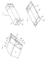
- the packing material is cut in the prescribed shape, and after rimpled to facilitate folding and forming, a longitudinal folding line to form a joining edge and a folding line to face the said folding line at the time of container forming, are folded and the two longitudinal edges are joined and seled to be converted to a flattened parallelepipedic blank (C) (refer to Fig. 5).
- the flattened packing containers (C) are piled in prescribed amount for transportation and then wrapped. These are carried to the packer for filling the contents, unwrapped therein and piled in magazines.
- the packing container blanks are raised to form a square-shaped cross section before being converted to packing containers inside the packer (refer to Fig. 6).
- this shape is given to the packing container blanks (C)
- these blanks are loaded onto the packer one after another to be filled with content liquid, and converted into sealed packing containers.
- packing container blanks raised to form a square-shaped cross section are ordinarily loaded onto the mandrel wheel of the packer, and the packing container blanks are formed with a bottom part by folding and sealing during rotation of the mandrel wheel. Thereafter, the packing container blanks are transferred to the conveyor, and go through the filling part thereon to be filled with the desired contents, followed by folding and sealing of the top to form the complete packing containers.
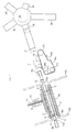
- Fig. 1 is a side view showing the relationship between the two rows of packing container blank raising devices in the front and rear, and the main conveyor 10 supplying blanks to the said devices.
- the two rows of raising devices located in the front and rear in relation to the conveyance direction of the main conveyor 10, are respectively equipped with a pair of discharging rollers 1 and 1′ that serve to push flattened parallelepipedic blanks C into the blank raising part where they are raised to form a square-shaped cross section, and one of the said rollers 1′ (diagonally above the other) has an elastic body such as an O-ring embedded onto the surface to be able to hold pushed blanks C.
- lifting conveyors 5 for loading flattened parallelepipedic blanks C at a constant pitch between the said discharging rollers 1 and 1′ synchronously with the rotation of the said discharging rollers and conveying blanks diagonally upward at an angle of 45° .
- two pushing claws 5b for pushing blanks C are set up at two places so they divide the conveyor length equally into two, and on both sides of the said timing belt 5a, a blank supporting rail 11 with a blank sliding surface slightly above the upper surface of the timing belt 5a is set up coupled with an auxiliary supporting plate 11′ having a sliding surfae of the same level as the said sliding surface, so that when the timing belt 5a moves, the blank C is moved diagonally upward pushed by the pushing claw 5b.
- This lifting conveyor 5 is equipped with timing belts 5a, blank supporting rails 11, and auxiliary supporting plates 11′ to be able to accommodate the longitudinal dimension of the blank C.
- blank supporters 31 and 32 On the blank discharge side of the above pair of rollers 1 and 1′ , are blank supporters 31 and 32, each equipped with a raising part 3′ that support both sides of the blank C pressed-opened across the rolling line at the front edge by the pusher mentioned later in the perpendicular direction to the rolling direction, and at the same time support blanks raised to form a square-shaped cross section.
- This pair of blank supporters 31 and 32 are set above and below the path of the pushing claw 12b of an unloading conveyor 12 to be mentioned later. Both sides across the pushing line of the above blank of the lower blank supporter 31, are open 90° to support and guide the corner of the blank C that has a square-shaped cross section, and one of the open sides leads to the raising part 3′ on the edge via a circular plane.
- the said blank supporter 31 has a window 3a cut-open at a prescribed width and length in the central part that is open for 90° across the above pushing line, whereon a path for a blank C rolled out from the pair of rollers 1 and 1′ is formed (see Fig. 2). Also, on the above rolling line, a pusher (2) for receiving and pressing an edge Ca of a flattened blank C that passed through the discharging rollers 1 and 1′, is attached at the top of the moving lever 13 that is guided by four grooved guide rollers 14, and is mounted in a forwardable and retreatable manner.
- a pair of left and right moving levers 13 and 13 of the two packing-container-blank-raising devices in the front and rear, are adhered to each other by a link 15 to move as a unit, wherein said link 15 is forwardable and retreatable (between lower left and upper right in the figure) via a linking rod 18 that is positioned in the diagonally upward direction with a spring 34 from a crank lever rocked by a pusher driving cam that rotates synchronously with the movement of a conveyor 10 on the side of the said conveyor 10 (left of conveyance direction of said conveyor).
- a pair of front and rear lifting conveyors 5 and 5 are synchronously driven with timing pulleys 20 and 20 at the upper edge of a pair of lifting conveyors 5 and 5, that are driven via a timing belt 23 by the timing pullex 19 at the upper edge of the main conveyor 10 that is driven at the same time as the above cam.
- a pair of front and rear discharging rollers 1 and 1 are rotated by timing pulleys 22 and 22 linked with said discharging rollers 1 and 1′ that are located, via a timing belt 24, upward from the timing pulleys 21 that are on the same axis and of the same diameter as timing pulleys 20 at the upper tip of lifting conveyors 5 in the rear (right hand side in the diagram), and upper discharging rollers 1′ and 1′ that are gear-linked with said discharging rollers 1 and 1, are rotated at the same speed.
- the pair of pushers 2 and 2 the pair of discharging rollers 1, 1′ and 1, 1′ in the front and rear, and the pair of lifting conveyors 5 and 5 are driven synchronously.
- Each blank C moving diagonally upward by pressure from pushing claw 5b of each lifting conveyor 5, is rolled out from a pair of discharging rollers 1 and 1′ in a flattened or nearly flattened condition (see Fig. 3a and b): shown only for one of the two blanks rolled out simultaneously (same hereafter).
- each pusher 2 advances toward discharging rollers 1 and 1′ to press-open the blank C, and to further press beyond the condition of a square-shaped cross section of the same, and when the pusher 2 is pressed in to the extreme position where both sides of blank C are fixed between raising parts 3′ and 3′ on both sides of blank supporters 31 and 32, blank C is opened nearly 180° , i.e. is almost flattened in the perpendicular direction to the pushing direction (see Fig. 3c). Thereafter, pusher 2 moves back from the discharging rollers 1, 1′ side and returns towards the original position but is maintained stationary, for a prescribed time, in an intermediate position (see Fig.
- the unloading conveyor 12 that loads the parallelepipedic blank C with a square-shaped cross section towards the mandrel wheel 30 (see Fig. 2) inside the packer in the longitudinal direction and whose pushing claw 12b does not go into the blank raising part comprising blank supporters 31 and 32, moves synchronously so that the blank C is rolled out during the time when it is raised to form a rectangular parallelepiped with a square-shaped cross section.
- a contact lever 8a rotating while contacting the front edge Ca of the blank C that is rolled out
- a front part opening lever 8 equipped with a protrusion Cb on one of the pair of bottom forming walls Cb and Cb′ interfacing with each other on the said contacting initial blank front edge side, so that when the contacting lever 8a is pushed and rotated by movement of the blank C, it presses the said protrusion Cb1 to open the blank Ca little from a folded condition, thereby after the blank C advances to the point where its above mentioned walls Cb and Cb′ are open (see Fig. 4 pusher 2 starts advancing to rollers 1 and 1′ side to widely open the blank that is already open slightly.
- Each blank entrance in the lower part of the above mentioned front and rear lifting conveyors 5 and 5 has a speed increasing timing pulley 37 mounted on the timing pulley 21 to have the same axis and rotates independently of said timing pullex, and each speed increasing timing pulley 37 is rotated at an increased speed via timing belt 25 from timing pulley 21 of the same axis and same diameter as the timing pulley 20 at the upper part of the left lifting conveyor 5, and the circumferential speed of the feeding roller 36 that is fixed with said speed increasing timing pulley 37 on the same axis, is increased by four times as the conveyance speed of the above mentioned lifting conveyor 5.
- a resilient material such as an O-ring embedded on the circumference as if to contact the circumference of the said feeding roller 36
- the feeding rollers 36 and 36 in the lower part of the above mentioned two rows of lifting conveyors 5 and 5 in the front and rear, are mounted near and above the one main conveyor 10 that consecutively conveys blanks C withdrawn one after another from left and right magazines not illustrated, and in the front lower part of the blank entrance of the feeding rollers 36 and 36′ in the front (left in the figure) is a guide plate for conveyance direction change that is freely advancable and retreatable in relation to the main conveyor 10 conveyance surface, wherein said guide plate 6 for changing conveyance direction vibrates synchronously with the movement of the pushing claw 10b moving together with the main conveyor, via vibrating levers 32 and 33 connected with movable guide plate direction change cam 38 adhered to the above mentioned pusher driving cam 16 on the same axis, which guides blanks C moving on the blank supporting rail 31 by the pressure of pushing claws 10b adhered at a constant pitch on the timing belt 10a of the main conveyor 10, into the gap between said feeding rollers 36 and 36′ one after another.
- a guide plate that is stable in relation to the conveyance surface of the main conveyor is set up, and it guides blanks C sent one after another by the pushing claw 10b from the blank supporting rail 31 into the gap between the pair of feeding rollers 36 and 36′ in the rear upper part.
- blanks C conveyed consecutively on the one main conveyor 10 are guided simultaneously into the two lifting conveyors 5 and 5 in the front and rear, and are raised simultaneously to form a square-shaped cross section.
- each blank C raised to have a square-shaped cross section at each blank raising part is discharged in the longitudinal direction by each unloading conveyor 12 facing said blank raising part.
- said each unloading conveyor 12 is mounted extending in the right angle direction relative to the front, and pushing claws 12b mounted on the said lifting conveyor suspended between a timing pulley 261 mounted on the frame 401 in front of the main frames 401 and 402 on both front and rear sides on which the raising device is mounted and a timing pulley 262 mounted at a prescribed place on the rear mandrel side of the rear frame 402, so as to divide the circumference of the conveyor in two, move synchronously with the raising of the blank C, pushing said blank C from the side to discharge in the direction of the mandrel wheel 30 that is on the discharging line.
- the above mentioned main frames 401, 402 and the mandrel wheel 30 are separated by a slight gap due to arrangement considerations, and the pushing on the side of the raised rectangular parallelepipedic blank C by the pushing claw 29b on the timing belt 29a suspended by timing pulleys 271, 272 and 273 of the loading conveyor 29 on the mandrel wheel 30 side, and the blanks are loaded from the path guided with parallelepipedic rollers onto the mandrel 30 rotating clockwise intermittently. That is, when the mandrel 28 connected radially to divide the clockwise and intermittently rotating mandrel wheel 30 equally into five is in an intermittently stopped condition, the rectangular parallelepipedic blank C raised on the mandrel 8 in the front is loaded.
- the mandrel 28 is mounted every 72° to divide the circumference equally into five, and in order to load the blank C on the mandrel 28 in the front and adjacent to the lower mandrel 28 that stops in the vertical direction, said mandrel 28 being inclined 18° from the horizontal direction, the path for loading said blank C onto the mandrel is also inclined 18° relative to the horizontal plane, and the main frames 401 and 402 are inclined 18° from vertical.
- the above mentioned front view (Fig. 1) shows the 18° inclination as vertical for convenience. Depending on the number of mandrels connected on the mandrel wheel 30, the inclination of the frame varies.
- FIG. 2 shows one of the paths going to the mandrel wheel 30 from two rows of unloading conveyors 12 and 12.
- flattened parallelepipedic packing container blanks C are withdrawn from the magazine not illustrated, and moved onto the main conveyor 10 to be conveyed consecutively on said main conveyor 10, and after divided into two rows of lifting conveyors 5 and 5 in the front and rear, they are raised at the blank raising part to be securely and simultaneously formed into two blanks with square-shaped cross section with no possibility of flat interfacing sides sticking together unopened, and they are loaded onto the two rows of mandrel wheels from the pair of unloading conveyors.
- opening of the blank that precedes raising of the blank is conducted by the front part opening lever 8, but this can be replaced by a method involving suction.
- rimpled and flattened parallelepipedic blanks rolled out from a pair of discharging rollers are overfolded nearly 180° past the point where the cross section is square by the pressure from the pusher, whereafter the pusher is moved backwards to form said parallelepipedic blanks of square cross section eliminating the folding tendency and maintaining a square cross section, allowing large overfolding, which was difficult with the said conventional device, and securing more firm maintenance of square cross section contributing to smooth formation of containers including loading of packing container blanks.
- consecutive rolling out of blanks by discharging rollers, raising of blanks to form a square-shaped cross section by the pressure and backward movement of the pusher, and discharging of raised blanks, are conducted synchronously so that the raising of flattened parallelepipedic blanks is conducted consecutively and efficiently.
- the device described in claim 4 is equipped with discharging rollers for pushing out flattened parallelepipedic blanks, lifting conveyors for conveying blanks to the said discharging rollers, supporters for blanks to be raised, and a pusher to advance or retreat it according to raising operation, wherefore by making discharge of the blanks through the discharging measure synchronously with raising of the blanks from the raising part, flattened parallelepipedic blanks are continuously and steadily raised.
- the cross section of the blank can be raised to form a square steadily because of the 90° opening of the receptacle of the pusher.
- the device described in claim 6 is equipped with a front part opening measure for opening blanks slightly prior to raising the blanks to form a square-shaped cross section by a pusher, which avoids the problem of blanks not raised to form a square-shaped cross section and twisted.
- a front part opening lever of a simple construction can open the blank slightly by using the blank moving force prior to the raising of the blank, and this method is quite simple compared to the ordinary construction in which cams are used to move the opening lever.
- the device described in claim 8 is equipped with a movable guide plate and a fixed gjide plate for changing conveyance direction, wherein blanks conveyed are guided into one of the lifting conveyors at the raising part by the former and into the other lifting conveyor by the latter fixed guide so that blanks can be loaded onto two rows of raising devices from one main conveyor for efficient raising.
Landscapes
- Mechanical Engineering (AREA)
- Engineering & Computer Science (AREA)
- Making Paper Articles (AREA)
- Shaping Of Tube Ends By Bending Or Straightening (AREA)
- Supplying Of Containers To The Packaging Station (AREA)
- Preparation Of Compounds By Using Micro-Organisms (AREA)
- Saccharide Compounds (AREA)
- Investigating Or Analysing Biological Materials (AREA)
- Cultivation Receptacles Or Flower-Pots, Or Pots For Seedlings (AREA)
- Bending Of Plates, Rods, And Pipes (AREA)
- Devices For Executing Special Programs (AREA)
- Electrotherapy Devices (AREA)
- Percussion Or Vibration Massage (AREA)
- Transition And Organic Metals Composition Catalysts For Addition Polymerization (AREA)
- Manufacture, Treatment Of Glass Fibers (AREA)
Claims (8)
- Verfahren zum Aufrichten zusammengelegter, rohrförmiger Zuschnitte zum Bilden von rechtwinkeligen, rohrförmigen Parallelepipeden mit den Verfahrensschritten:
Ausrollen der zusammengelegten Zuschnitte C durch ein Paar von Austragswalzen (1, 1');
Empfangen und Abstützen einer Vorderkante (Ca) des Zuschnitts (C), der von dem Paar der Austragswalzen (1, 1') zugeführt wurde durch eine Schubvorrichtung (2);
Bewegen der Schubvorrichtung (2) gegen die Vorderkante (Ca) des Zuschnitts (C) und Drücken der Frontkante (Ca) rückwärts in die Richtung entgegengesetzt der Rollrichtung, während die Rückkante des Zuschnitts (10) durch die Austragswalzen (1, 1') abgestützt wird, bis die nebeneinander liegenden Wände des Zuschnittes auf der Austragsseite eine Stützvorrichtung auf der Austragsseite berühren und von dieser abgestützt werden, wodurch der zusammengelegte Zuschnitt (C) geöffnet wird, um ein erstes rechtwinkeliges Parallelepiped mit im wesentlichen quadratischem Querschnitt zu bilden;
Fortführung der Schubbewegung bis der Zuschnitt sich auf nahezu 180° geöffnet hat und dabei eine nahezu zusammengelegte Stellung in Richtung quer zur Vorschubrichtung erreicht, während die nebeneinander liegenden Wände des Zuschnittes auf der Austragsseite und beide Kanten des Zuschnittes (C), die in Querrichtung zur Vorschubrichtung ausgebildet sind, durch die Stützvorrichtung abgestützt werden;
und Zurückziehen der Schubvorrichtung (2) in die Vorschubrichtung, bis der Zuschnitt (C) durch elastischen Angreifen der Schubvorrichtung (2) die Form eines zweiten rechtwinkeligen Parallelepipeds mit im wesentlichen quadratischem Querschnitt annimmt, während die nebeneinander liegenden Wände des Zuschnittes auf der Austragsseite durch die Stützvorrichtung abgestützt werden. - Verfahren nach Anspruch 1,
dadurch gekennzeichnet, daß vor dem Bewegen der Schubvorrichtung (2) gegen die Frontkante (Ca) des Zuschnittes (C) und dem Schieben der Frontkante rückwärts in die Richtung entgegengesetzt der Austragsrichtung, ein Spalt zwischen einem Paar von Wandteilen (Cb, Cb') ein wenig geöffnet wird. - Verfahren nach einem der Ansprüche 1 oder 2,
dadurch gekennzeichnet, daß die Verfahrensschritte: Ausrollen des zusammengelegten Zuschnitts (C) durch ein Paar von Austragswalzen (1, 1'), Bewegen der Schubvorrichtung (2) rückwärts in die Richtung entgegengesetzt zur Vorschubrichtung, Zurückziehen der Schubvorrichtung (2) in Vorschubrichtung und Entladen des Zuschnittes (C) mit quadratischem Querschnitt periodisch und sequentiell für jeden Zuschnitt durchgeführt werden. - Vorrichtung zum Aufrichten zusammengelegter, rohrförmiger Zuschnitte, um rechtwinkelige, rohrförmige Parallelepipede zu bilden gemäß dem Verfahren der Ansprüche 1 bis 3 mit mindestens:
einem Paar von Austragswalzen (1, 1');
einem Hebeförderer (5), der vor den Walzen (1, 1') in Förderrichtung angeordnet ist, um die zusammengelegten Zuschnitte (C) auf einer Rollinie zwischen dem Paar von Austragswalzen mit einer konstanten Steigung zu fördern;
Zuschnitt-Stützvorrichtungen (3₁, 3₂) die auf der Austragsseite der Austragswalzen (1, 1') angeordent sind, um die nebeneinander liegenden Wände der Rückkante des Zuschnitts auf der Austragsseite und die beiden Kanten des Zuschnitts, die in der Richtung quer zur Fördervorrichtung liegen, abzustützen;
und einer Schieber-Bewege-Vorrichtung (4), die auf der Rollinie des Zuschnitts (C) befestigt ist und mit den Schubvorrichtungen versehen ist, die beweglich in Vorwärts- und Rückwärtsrichtung sequentiell mit dem Entladen des Zuschnitts bewegbar sind, so daß jede Schubvorrichtung (2) die Frontkante (Ca) des zusammengelegten, rohrförmigen Zuschnitts, der von den Austragswalzen (1, 1') entladen wurde, rückwärts stößt in die Richtung entgegengesetzt zur Förderrichtung, um den Zuschnitt zu öffnen und die ersten rechtwinkeligen Parallelepipede mit im wesentlichen quadratischem Querschnitt zu bilden, dann die Frontkante des Zuschnittes weiter stößt zum Öffnen des Zuschnittes auf nahezu 180° und zum Erreichen eines nahezu zusammengefalteten Zustandes in Querrichtung zur Förderrichtung, und daraufhin sich in die Förderrichtung zurückzieht, bis der Zuschnitt durch elastischen Eingriff der Schubvorrichtung den zweiten rechtwinkeligen Parallelepiped-Zustand mit im wesentlichen quadratischem Querschnitt erreicht und beibehält, wobei der Zuschnitt einem Entladeförderer gegenübersteht und in Längsrichtung des Zuschnittes gefördert wird. - Verfahren nach Anspruch 4,
dadurch gekennzeichnet, daß jede Schubvorrichtung (2) eine Aufnahme aufweist, die zur Seite der Walzen (1, 1') über die Zuschnittrollinie um 90 ° geöffnet ist. - Verfahren nach Anspruch 5,
gekennzeichnet durch einen Frontöffnungsmechanismus (8) zum geringfügigen Öffnen des Zuschnitts (C) vor der Vorwärtsbewegung der Schubvorrichtung (2) in Richtung auf die Seite des Walzenpaares (1, 1'), wobei der Frontöffnungsmechanismus (8) mindestens einer Seite eines Paars von Zwischenwandungen gegenübersteht an der Vorderkante des Zuschnitts (C), welches auf der Austragsseite der Austragswalzen (1, 1') ausgerollt wird. - Verfahren nach Anspruch 6,
dadurch gekennzeichnet, daß der Frontteil-Öffnungsmechanismus (8) einen Kontakthebel (8a) aufweist, der so angeordnet ist, daß er durch die Frontkante des Zuschnittes (C) berührt und gedrückt wird, wenn dieser von den Austragswalzen (1, 1') ausgerollt wird und sich längs der Rollinie bewegt, wodurch sich der Frontteil-Öffnungsmechanismus (8) leicht dreht und der Frontteil-Öffnungsmechanismus (8) einen Druckhebel (8b) aufweist zum Öffnen eines Paars von Wandungen aus der zusammengefalteten Stellung durch Drücken der Wandungen an einem vorragenden Teil (Cb₁) unter Bewegung des Zuschnitts (C), während der Druckhebel (8b) dem vorstehenden Teil (Cb₁) auf einer Wandung des Paars von Zwischenwandungen (Cb, Cb') auf der Frontkantenseite des Zuschnitts zum Zeitpunkt des Kontaktes gegenübersteht. - Verfahren nach einem der Ansprüche 4 bis 7,
mit einer Schubvorrichtungsbewegungsvorrichtung (4) mit mindestens einem Paar von Zuschnittaufrichtteilen, die nebeneinander befestigt sind, und von denen jeder mit einem Paar von Austragswalzen (1, 1') und Zuschnittstützen (3₁, 3₂) versehen ist, wobei zwei Hubförderer (5) zum Fördern des Zuschnittes (C) zum Aufrichtteil vorgesehen sind vor und hinter der Laderichtung am oberen Teil eines Hauptförderers (10), der in Horizontalrichtung angeordnet ist, und mit einer beweglichen Führungsplatte (6) zum Ändern der Förderrichtung, die frei vorwärts und rückwärts bewegbar ist in Bezug auf die Förderfläche des Hauptförderers (10), die unter dem vorderen Hubförderer angeordnet ist, um die geförderten Zuschnitte von der Oberseite des Hauptförderers (10) abzuführen, und mit einer festen Führungsplatte (7) zum Ändern der Förderrichtung relativ zur Förderfläche des Hauptförderers (10), die unterhalb des Hubförderers angeordnet ist, wobei die Führungsplatte (6) synchron zum Antrieb des Hubförderers (5) und des Hauptförderers (10) angetrieben wird und alternierend den Zuschnitt (C), der in Folge auf dem Hauptförderer (10) gefördert wird, auf die Hubförderer (5) am Anfang oder am Ende zuführt, um sie in den Spalt zwischen das Paar von Förderwalzen (1, 1') zu führen.
Priority Applications (1)
| Application Number | Priority Date | Filing Date | Title |
|---|---|---|---|
| AT89115203T ATE96750T1 (de) | 1988-08-24 | 1989-08-17 | Verfahren und vorrichtung zum aufrichten zusammengelegter rohrfoermiger zuschnitte. |
Applications Claiming Priority (2)
| Application Number | Priority Date | Filing Date | Title |
|---|---|---|---|
| JP209701/88 | 1988-08-24 | ||
| JP63209701A JP2739483B2 (ja) | 1988-08-24 | 1988-08-24 | 平らにされた筒状ブランクの立上げ方法とその装置 |
Publications (2)
| Publication Number | Publication Date |
|---|---|
| EP0356824A1 EP0356824A1 (de) | 1990-03-07 |
| EP0356824B1 true EP0356824B1 (de) | 1993-11-03 |
Family
ID=16577204
Family Applications (1)
| Application Number | Title | Priority Date | Filing Date |
|---|---|---|---|
| EP89115203A Expired - Lifetime EP0356824B1 (de) | 1988-08-24 | 1989-08-17 | Verfahren und Vorrichtung zum Aufrichten zusammengelegter rohrförmiger Zuschnitte |
Country Status (12)
| Country | Link |
|---|---|
| US (1) | US5033975A (de) |
| EP (1) | EP0356824B1 (de) |
| JP (1) | JP2739483B2 (de) |
| AT (1) | ATE96750T1 (de) |
| AU (1) | AU620433B2 (de) |
| CA (1) | CA1312494C (de) |
| DE (1) | DE68910438T2 (de) |
| DK (1) | DK169468B1 (de) |
| ES (1) | ES2045303T3 (de) |
| FI (1) | FI88139C (de) |
| IE (1) | IE62975B1 (de) |
| NO (1) | NO177694C (de) |
Cited By (1)
| Publication number | Priority date | Publication date | Assignee | Title |
|---|---|---|---|---|
| CN104245516A (zh) * | 2012-03-30 | 2014-12-24 | 爱洛帕克系统股份公司 | 用于在装填机中降低包装外壳的复位力的装置和方法 |
Families Citing this family (8)
| Publication number | Priority date | Publication date | Assignee | Title |
|---|---|---|---|---|
| JP2555462Y2 (ja) * | 1992-09-29 | 1997-11-26 | 四国化工機株式会社 | ブランク供給装置 |
| ITBO20020485A1 (it) * | 2002-07-25 | 2004-01-26 | Azionaria Costruzioni Acma Spa | Impianto per formare contenitori , in particolare contenitori per prodotti alimentari |
| JP2008247441A (ja) * | 2007-03-30 | 2008-10-16 | Toppan Printing Co Ltd | 液体用紙容器 |
| JP5347680B2 (ja) * | 2009-04-20 | 2013-11-20 | Tdk株式会社 | 開箱装置および箱詰め装置 |
| DE102016109996A1 (de) * | 2016-04-04 | 2017-10-05 | Sig Technology Ag | Verfahren und Vorrichtung zum Bilden von einseitig offenen Packungskörpern aus beidseitig offenen Packungsmänteln |
| DE102017114814A1 (de) | 2017-07-03 | 2019-01-03 | Sig Technology Ag | Verfahren und Vorrichtung zum Bilden von einseitig offenen Packungskörpern mit einem oszillierenden Greifer |
| CN109677008B (zh) * | 2019-01-11 | 2020-04-03 | 浙江骏驰纸制品有限公司 | 一种用于纸质印刷的纸板固定机构 |
| KR102551135B1 (ko) * | 2023-01-25 | 2023-07-03 | 박양순 | 박스 제함기 |
Family Cites Families (13)
| Publication number | Priority date | Publication date | Assignee | Title |
|---|---|---|---|---|
| BE530028A (de) * | ||||
| DE491828C (de) * | 1929-02-22 | 1930-02-12 | United Cigarette Mach Co Inc | Verfahren und Vorrichtung zum Umbrechen von Schachtelscheiden |
| US2241817A (en) * | 1939-05-13 | 1941-05-13 | Pneumatic Scale Corp | Packaging machine |
| US3187646A (en) * | 1959-12-04 | 1965-06-08 | Ex Cell O Corp | Packaging machine for erecting and sealing plastic coated paperboard containers |
| US3044371A (en) * | 1960-02-02 | 1962-07-17 | Vend A Box Inc | Box erecting and vending machine |
| US3293998A (en) * | 1963-10-21 | 1966-12-27 | Superior Packaging Equipment C | Container opening device and method of opening a knock-down container |
| US3418894A (en) * | 1966-05-20 | 1968-12-31 | Jivoin Anton | Carton opening device |
| US4057008A (en) * | 1976-09-16 | 1977-11-08 | R. A. Jones & Co. Inc. | Carton erecting apparatus |
| JPS5815365B2 (ja) * | 1979-04-23 | 1983-03-25 | 一義 細川 | 紙製箱枠の自動折返し移送方法 |
| SE436271B (sv) * | 1981-03-13 | 1984-11-26 | Tetra Pak Int | Anordning for resning och forflyttning av forpackningsbehallaremnen |
| SE8301122D0 (sv) * | 1983-03-01 | 1983-03-01 | Tetra Pak Int | Anordning for transport och resning av forpackningsbehallaremnen |
| US4530692A (en) * | 1983-08-25 | 1985-07-23 | Consolidated Papers, Inc. | Apparatus for opening folded corrugated cartons |
| JPS6355031A (ja) * | 1986-08-20 | 1988-03-09 | 四国化工機株式会社 | 包装機械におけるブランク供給装置 |
-
1988
- 1988-08-24 JP JP63209701A patent/JP2739483B2/ja not_active Expired - Lifetime
-
1989
- 1989-07-28 FI FI893614A patent/FI88139C/fi not_active IP Right Cessation
- 1989-08-17 EP EP89115203A patent/EP0356824B1/de not_active Expired - Lifetime
- 1989-08-17 ES ES89115203T patent/ES2045303T3/es not_active Expired - Lifetime
- 1989-08-17 DE DE89115203T patent/DE68910438T2/de not_active Expired - Fee Related
- 1989-08-17 AT AT89115203T patent/ATE96750T1/de not_active IP Right Cessation
- 1989-08-18 CA CA000608704A patent/CA1312494C/en not_active Expired - Fee Related
- 1989-08-22 NO NO893369A patent/NO177694C/no unknown
- 1989-08-22 IE IE269289A patent/IE62975B1/en not_active IP Right Cessation
- 1989-08-23 DK DK415389A patent/DK169468B1/da not_active IP Right Cessation
- 1989-08-23 US US07/397,245 patent/US5033975A/en not_active Expired - Fee Related
- 1989-08-24 AU AU40187/89A patent/AU620433B2/en not_active Ceased
Cited By (2)
| Publication number | Priority date | Publication date | Assignee | Title |
|---|---|---|---|---|
| CN104245516A (zh) * | 2012-03-30 | 2014-12-24 | 爱洛帕克系统股份公司 | 用于在装填机中降低包装外壳的复位力的装置和方法 |
| CN104245516B (zh) * | 2012-03-30 | 2016-09-07 | 爱洛帕克系统股份公司 | 用于在装填机中降低包装外壳的复位力的装置和方法 |
Also Published As
| Publication number | Publication date |
|---|---|
| EP0356824A1 (de) | 1990-03-07 |
| JP2739483B2 (ja) | 1998-04-15 |
| CA1312494C (en) | 1993-01-12 |
| FI88139C (fi) | 1993-04-13 |
| NO177694C (no) | 1995-11-08 |
| IE62975B1 (en) | 1995-03-08 |
| AU620433B2 (en) | 1992-02-20 |
| FI893614A7 (fi) | 1990-02-25 |
| AU4018789A (en) | 1990-03-01 |
| ATE96750T1 (de) | 1993-11-15 |
| NO177694B (no) | 1995-07-31 |
| DK169468B1 (da) | 1994-11-07 |
| NO893369L (no) | 1990-02-26 |
| US5033975A (en) | 1991-07-23 |
| FI88139B (fi) | 1992-12-31 |
| NO893369D0 (no) | 1989-08-22 |
| DK415389D0 (da) | 1989-08-23 |
| ES2045303T3 (es) | 1994-01-16 |
| IE892692L (en) | 1990-02-24 |
| JPH0259332A (ja) | 1990-02-28 |
| DK415389A (da) | 1990-02-25 |
| DE68910438T2 (de) | 1994-03-10 |
| FI893614A0 (fi) | 1989-07-28 |
| DE68910438D1 (de) | 1993-12-09 |
Similar Documents
| Publication | Publication Date | Title |
|---|---|---|
| US6202392B1 (en) | Flexible tissue handling apparatus | |
| JPH0311132Y2 (de) | ||
| US4918906A (en) | Method and apparatus for producing a bag-in-carton | |
| US3810344A (en) | Machine for packaging flexible articles | |
| EP0305789B1 (de) | Vorrichtung und Verfahren zum Anbringen von flexiblen, länglichen Gegenständen an Packungen | |
| US4173106A (en) | Carton forming method | |
| US20050079965A1 (en) | Container forming machine | |
| US3585776A (en) | Process and apparatus for manufacturing a box completely filled with a stack of articles | |
| JPS5918246B2 (ja) | 巻タバコ用の折たたみできる箱を作つてそれに充てんする方法および装置 | |
| CN113353344B (zh) | 一种物料包装生产线 | |
| US4464880A (en) | Method and apparatus for introducing stacks of sheets into prefabricated cartons or the like | |
| US5033975A (en) | Method of and a device for raising flattened parallelepipedic blanks | |
| JPH0549529B2 (de) | ||
| US5150562A (en) | Method and apparatus for packaging resiliently deformable articles | |
| US4024693A (en) | Carton forming apparatus | |
| CN215285427U (zh) | 一种糕点的自动包装生产线 | |
| JP2001199533A (ja) | 物品の自動集合装置 | |
| US5697877A (en) | Apparatus for feeding packaging machines | |
| JPH0769314A (ja) | タオル包装機 | |
| US4709529A (en) | High-speed wrapping machine | |
| CN1104601A (zh) | 长方体货包的包装设备 | |
| JPH05177744A (ja) | 製函方法及び装置 | |
| JPS61241133A (ja) | 製函方法及び製函装置 | |
| JPH0511129Y2 (de) | ||
| CN113246531A (zh) | 一种瓦楞纸箱生产用封箱装置 |
Legal Events
| Date | Code | Title | Description |
|---|---|---|---|
| PUAI | Public reference made under article 153(3) epc to a published international application that has entered the european phase |
Free format text: ORIGINAL CODE: 0009012 |
|
| AK | Designated contracting states |
Kind code of ref document: A1 Designated state(s): AT BE CH DE ES FR GB IT LI NL SE |
|
| 17P | Request for examination filed |
Effective date: 19900828 |
|
| 17Q | First examination report despatched |
Effective date: 19920116 |
|
| GRAA | (expected) grant |
Free format text: ORIGINAL CODE: 0009210 |
|
| AK | Designated contracting states |
Kind code of ref document: B1 Designated state(s): AT BE CH DE ES FR GB IT LI NL SE |
|
| REF | Corresponds to: |
Ref document number: 96750 Country of ref document: AT Date of ref document: 19931115 Kind code of ref document: T |
|
| ITF | It: translation for a ep patent filed | ||
| REF | Corresponds to: |
Ref document number: 68910438 Country of ref document: DE Date of ref document: 19931209 |
|
| REG | Reference to a national code |
Ref country code: ES Ref legal event code: FG2A Ref document number: 2045303 Country of ref document: ES Kind code of ref document: T3 |
|
| ET | Fr: translation filed | ||
| PLBE | No opposition filed within time limit |
Free format text: ORIGINAL CODE: 0009261 |
|
| STAA | Information on the status of an ep patent application or granted ep patent |
Free format text: STATUS: NO OPPOSITION FILED WITHIN TIME LIMIT |
|
| 26N | No opposition filed | ||
| EAL | Se: european patent in force in sweden |
Ref document number: 89115203.5 |
|
| PGFP | Annual fee paid to national office [announced via postgrant information from national office to epo] |
Ref country code: AT Payment date: 19980723 Year of fee payment: 10 |
|
| PGFP | Annual fee paid to national office [announced via postgrant information from national office to epo] |
Ref country code: CH Payment date: 19980727 Year of fee payment: 10 |
|
| PGFP | Annual fee paid to national office [announced via postgrant information from national office to epo] |
Ref country code: NL Payment date: 19980728 Year of fee payment: 10 |
|
| PGFP | Annual fee paid to national office [announced via postgrant information from national office to epo] |
Ref country code: BE Payment date: 19980813 Year of fee payment: 10 |
|
| PGFP | Annual fee paid to national office [announced via postgrant information from national office to epo] |
Ref country code: SE Payment date: 19990802 Year of fee payment: 11 Ref country code: FR Payment date: 19990802 Year of fee payment: 11 Ref country code: DE Payment date: 19990802 Year of fee payment: 11 |
|
| PGFP | Annual fee paid to national office [announced via postgrant information from national office to epo] |
Ref country code: GB Payment date: 19990803 Year of fee payment: 11 |
|
| PGFP | Annual fee paid to national office [announced via postgrant information from national office to epo] |
Ref country code: ES Payment date: 19990813 Year of fee payment: 11 |
|
| PG25 | Lapsed in a contracting state [announced via postgrant information from national office to epo] |
Ref country code: AT Free format text: LAPSE BECAUSE OF NON-PAYMENT OF DUE FEES Effective date: 19990817 |
|
| PG25 | Lapsed in a contracting state [announced via postgrant information from national office to epo] |
Ref country code: LI Free format text: LAPSE BECAUSE OF NON-PAYMENT OF DUE FEES Effective date: 19990831 Ref country code: CH Free format text: LAPSE BECAUSE OF NON-PAYMENT OF DUE FEES Effective date: 19990831 Ref country code: BE Free format text: LAPSE BECAUSE OF NON-PAYMENT OF DUE FEES Effective date: 19990831 |
|
| BERE | Be: lapsed |
Owner name: TETRA PAK A.B. Effective date: 19990831 |
|
| PG25 | Lapsed in a contracting state [announced via postgrant information from national office to epo] |
Ref country code: NL Free format text: LAPSE BECAUSE OF NON-PAYMENT OF DUE FEES Effective date: 20000301 |
|
| REG | Reference to a national code |
Ref country code: CH Ref legal event code: PL |
|
| NLV4 | Nl: lapsed or anulled due to non-payment of the annual fee |
Effective date: 20000301 |
|
| PG25 | Lapsed in a contracting state [announced via postgrant information from national office to epo] |
Ref country code: GB Free format text: LAPSE BECAUSE OF NON-PAYMENT OF DUE FEES Effective date: 20000817 |
|
| PG25 | Lapsed in a contracting state [announced via postgrant information from national office to epo] |
Ref country code: SE Free format text: LAPSE BECAUSE OF NON-PAYMENT OF DUE FEES Effective date: 20000818 Ref country code: ES Free format text: LAPSE BECAUSE OF NON-PAYMENT OF DUE FEES Effective date: 20000818 |
|
| GBPC | Gb: european patent ceased through non-payment of renewal fee |
Effective date: 20000817 |
|
| EUG | Se: european patent has lapsed |
Ref document number: 89115203.5 |
|
| PG25 | Lapsed in a contracting state [announced via postgrant information from national office to epo] |
Ref country code: FR Free format text: LAPSE BECAUSE OF NON-PAYMENT OF DUE FEES Effective date: 20010430 |
|
| PG25 | Lapsed in a contracting state [announced via postgrant information from national office to epo] |
Ref country code: DE Free format text: LAPSE BECAUSE OF NON-PAYMENT OF DUE FEES Effective date: 20010501 |
|
| REG | Reference to a national code |
Ref country code: FR Ref legal event code: ST |
|
| REG | Reference to a national code |
Ref country code: ES Ref legal event code: FD2A Effective date: 20010911 |
|
| PG25 | Lapsed in a contracting state [announced via postgrant information from national office to epo] |
Ref country code: IT Free format text: LAPSE BECAUSE OF NON-PAYMENT OF DUE FEES;WARNING: LAPSES OF ITALIAN PATENTS WITH EFFECTIVE DATE BEFORE 2007 MAY HAVE OCCURRED AT ANY TIME BEFORE 2007. THE CORRECT EFFECTIVE DATE MAY BE DIFFERENT FROM THE ONE RECORDED. Effective date: 20050817 |