EP0357164A1 - Ultraschallverfahren und Schaltungen zu deren Durchführung - Google Patents
Ultraschallverfahren und Schaltungen zu deren Durchführung Download PDFInfo
- Publication number
- EP0357164A1 EP0357164A1 EP89250017A EP89250017A EP0357164A1 EP 0357164 A1 EP0357164 A1 EP 0357164A1 EP 89250017 A EP89250017 A EP 89250017A EP 89250017 A EP89250017 A EP 89250017A EP 0357164 A1 EP0357164 A1 EP 0357164A1
- Authority
- EP
- European Patent Office
- Prior art keywords
- frequency
- ultrasound
- transducer
- mhz
- function generator
- Prior art date
- Legal status (The legal status is an assumption and is not a legal conclusion. Google has not performed a legal analysis and makes no representation as to the accuracy of the status listed.)
- Granted
Links
- 238000000034 method Methods 0.000 title claims abstract description 39
- 238000001228 spectrum Methods 0.000 claims abstract description 16
- 239000002961 echo contrast media Substances 0.000 claims abstract description 9
- 238000011156 evaluation Methods 0.000 claims abstract description 9
- 238000002604 ultrasonography Methods 0.000 claims description 28
- 230000005284 excitation Effects 0.000 claims description 18
- 239000000463 material Substances 0.000 claims description 12
- 238000012545 processing Methods 0.000 claims description 10
- 239000000725 suspension Substances 0.000 claims description 6
- 230000001360 synchronised effect Effects 0.000 claims description 3
- 239000003795 chemical substances by application Substances 0.000 claims description 2
- 239000000126 substance Substances 0.000 claims description 2
- 239000000839 emulsion Substances 0.000 claims 1
- 239000000243 solution Substances 0.000 claims 1
- 230000008901 benefit Effects 0.000 abstract description 2
- 238000007689 inspection Methods 0.000 abstract 1
- 230000005540 biological transmission Effects 0.000 description 11
- 238000005259 measurement Methods 0.000 description 8
- 230000004044 response Effects 0.000 description 6
- 239000002872 contrast media Substances 0.000 description 4
- 238000010586 diagram Methods 0.000 description 3
- 230000000694 effects Effects 0.000 description 3
- 230000003993 interaction Effects 0.000 description 3
- 230000035515 penetration Effects 0.000 description 3
- 238000012360 testing method Methods 0.000 description 3
- 229910001868 water Inorganic materials 0.000 description 3
- 238000012512 characterization method Methods 0.000 description 2
- 239000011888 foil Substances 0.000 description 2
- 230000003595 spectral effect Effects 0.000 description 2
- 230000000007 visual effect Effects 0.000 description 2
- 238000004458 analytical method Methods 0.000 description 1
- 230000008859 change Effects 0.000 description 1
- 238000006243 chemical reaction Methods 0.000 description 1
- 238000012937 correction Methods 0.000 description 1
- 230000008878 coupling Effects 0.000 description 1
- 238000010168 coupling process Methods 0.000 description 1
- 238000005859 coupling reaction Methods 0.000 description 1
- 239000013078 crystal Substances 0.000 description 1
- 230000001934 delay Effects 0.000 description 1
- 238000005516 engineering process Methods 0.000 description 1
- 238000003384 imaging method Methods 0.000 description 1
- 238000011835 investigation Methods 0.000 description 1
- 239000011159 matrix material Substances 0.000 description 1
- 238000000386 microscopy Methods 0.000 description 1
- 230000010355 oscillation Effects 0.000 description 1
- 238000004154 testing of material Methods 0.000 description 1
- 230000009466 transformation Effects 0.000 description 1
- 238000000411 transmission spectrum Methods 0.000 description 1
- 230000001960 triggered effect Effects 0.000 description 1
- 229960003853 ultrasound contrast media Drugs 0.000 description 1
- XLYOFNOQVPJJNP-UHFFFAOYSA-N water Substances O XLYOFNOQVPJJNP-UHFFFAOYSA-N 0.000 description 1
Images



Classifications
-
- G—PHYSICS
- G01—MEASURING; TESTING
- G01S—RADIO DIRECTION-FINDING; RADIO NAVIGATION; DETERMINING DISTANCE OR VELOCITY BY USE OF RADIO WAVES; LOCATING OR PRESENCE-DETECTING BY USE OF THE REFLECTION OR RERADIATION OF RADIO WAVES; ANALOGOUS ARRANGEMENTS USING OTHER WAVES
- G01S7/00—Details of systems according to groups G01S13/00, G01S15/00, G01S17/00
- G01S7/52—Details of systems according to groups G01S13/00, G01S15/00, G01S17/00 of systems according to group G01S15/00
- G01S7/52017—Details of systems according to groups G01S13/00, G01S15/00, G01S17/00 of systems according to group G01S15/00 particularly adapted to short-range imaging
- G01S7/52023—Details of receivers
- G01S7/52036—Details of receivers using analysis of echo signal for target characterisation
- G01S7/52038—Details of receivers using analysis of echo signal for target characterisation involving non-linear properties of the propagation medium or of the reflective target
-
- A—HUMAN NECESSITIES
- A61—MEDICAL OR VETERINARY SCIENCE; HYGIENE
- A61B—DIAGNOSIS; SURGERY; IDENTIFICATION
- A61B8/00—Diagnosis using ultrasonic, sonic or infrasonic waves
-
- G—PHYSICS
- G01—MEASURING; TESTING
- G01S—RADIO DIRECTION-FINDING; RADIO NAVIGATION; DETERMINING DISTANCE OR VELOCITY BY USE OF RADIO WAVES; LOCATING OR PRESENCE-DETECTING BY USE OF THE REFLECTION OR RERADIATION OF RADIO WAVES; ANALOGOUS ARRANGEMENTS USING OTHER WAVES
- G01S7/00—Details of systems according to groups G01S13/00, G01S15/00, G01S17/00
- G01S7/52—Details of systems according to groups G01S13/00, G01S15/00, G01S17/00 of systems according to group G01S15/00
-
- G—PHYSICS
- G01—MEASURING; TESTING
- G01N—INVESTIGATING OR ANALYSING MATERIALS BY DETERMINING THEIR CHEMICAL OR PHYSICAL PROPERTIES
- G01N2291/00—Indexing codes associated with group G01N29/00
- G01N2291/02—Indexing codes associated with the analysed material
- G01N2291/024—Mixtures
- G01N2291/02491—Materials with nonlinear acoustic properties
-
- G—PHYSICS
- G01—MEASURING; TESTING
- G01S—RADIO DIRECTION-FINDING; RADIO NAVIGATION; DETERMINING DISTANCE OR VELOCITY BY USE OF RADIO WAVES; LOCATING OR PRESENCE-DETECTING BY USE OF THE REFLECTION OR RERADIATION OF RADIO WAVES; ANALOGOUS ARRANGEMENTS USING OTHER WAVES
- G01S15/00—Systems using the reflection or reradiation of acoustic waves, e.g. sonar systems
- G01S15/88—Sonar systems specially adapted for specific applications
- G01S15/89—Sonar systems specially adapted for specific applications for mapping or imaging
- G01S15/8906—Short-range imaging systems; Acoustic microscope systems using pulse-echo techniques
- G01S15/8979—Combined Doppler and pulse-echo imaging systems
Definitions
- the invention relates to ultrasonic methods according to the preamble of claims 1 or 2 and circuits for carrying them out.
- ultrasound waves are radiated into an examination area for selective image display and / or evaluation of the Doppler spectrum.
- Combined transmit / receive transducers are usually used in the methods and devices for material testing and for the examination of biological tissue.
- the crystals of the vibrators and the device electronics define a sound frequency (f o ) that is the same for sending and receiving.
- the reflected and / or backscattered signal is received in the same frequency range in the pulse-echo method.
- Such devices and methods are also used in the examination of biological tissues using ultrasound contrast agents.
- Signal components lying outside the specified frequency range such as vibrations in a harmonic relationship to the transmission frequency, are used for the visual representation of the examination object and other analyzes such as B. Doppler measurements are not used. In the previously known methods and device systems, several transducers are also used to cover a larger frequency range, which are exchanged during the examination.
- the invention is based on the object of expanding the field of application of ultrasound methods for objects which are resistant to sound intensity, in particular biological tissue, for selective image display and evaluation of the Doppler spectrum and of creating circuits for carrying out these methods.
- ⁇ is an even multiple of the denominator, the corresponding vibrations are the harmonics. If ⁇ ⁇ is the denominator, these vibrations are referred to in the literature as subharmonics. If ⁇ > than the denominator, it is an ultraharmonic oscillation.
- a selective evaluation of the signal components influenced by the input materials or media as well as a selective representation of the areas filled by these means is possible without a previously required difference between two or more before and after applying the materials or media.
- the Doppler effect can be evaluated free of artifacts.
- Nonlinear scattering bodies are advantageously introduced into the investigation area.
- a non-linear ultrasound contrast agent in the form of a solution or suspension and in particular microbubbles or agents producing microbubbles can also be introduced into the examination area.
- microbubble suspension with a concentration of 10 ⁇ 3% by weight to 30% by weight of dry substance in the suspension medium leads to good results, surprisingly the lower lower limit of 10 ⁇ 3% by weight being achieved with the method and the circuit according to the invention.
- the sound transducer is advantageously excited by means of a function generator with which RF bursts with adjustable amplitude and adjustable center frequency (f T ) in the range from 0.3 MHz to 22 MHz, preferably 1 MHz to 11 MHz and with 0.5 to 20, preferably 1-5 periods are generated. It has proven to be particularly advantageous to evaluate frequencies that are lower than the sound transducer (transmitter) center frequency f T.
- time window length and number of periods per burst are set between optimal frequency resolution and optimal spatial resolution.
- the circuit according to the invention for carrying out the method described above has a function generator, the output of which via a S / E switch (transmitter-receiver) switch which is synchronized by the function generator and which is followed by a signal processing system, with the transducer of an acoustically highly damped, electrically adapted, broadband Transducer element is connected.
- a S / E switch transmitter-receiver
- the function generator is connected to the input of a converter, the output of which is connected to a signal processing system.
- the burst generated by the function generator is passed to the transducer oscillator and the signal received by the transducer is passed on to the evaluation system when the S / E circuit is in the "received” position.
- the input and output are separated in the converter, so that an S / E switch is not required.
- a converter element whose center frequency f T is greater than the upper limit of the working range is used with particular advantage.
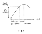
- This transducer element is designed so that the sound intensity emitted by it as a function of the frequency in the frequency range below the excitation or center frequency f T has a positive first derivative according to the frequency, which is approximately constant in particular in the working area or that the sound intensity in the working area itself has a constant value. Due to this almost straight frequency response in the working area, a similar frequency response, in particular the attenuation, can be largely compensated for in the sonicated examination area.
- This circuit and the converter used make it possible to change the frequency used for the examination without changing the transducer.
- the respectively optimal ratio of spatial resolution and frequency resolution can be selected.
- the method according to the invention can advantageously be carried out by means of a circuit which has a multi-element converter with converter elements applied with a phase delay in order to carry out a phase array or a dynamically focused method.
- the output of a function generator is connected via an n-way signal divider, n computer-controlled delay circuits and n S / E switches controlled by the function generator or a computer to the inputs of n acoustically highly damped, electrically adapted broadband converter elements, the outputs of which are connected via n S / E are each connected to an m-way signal divider.
- These m-way signal dividers are each via m delay circuits and m fixed or variable circuits for frequency band selection and also connected to a system for the selective further processing of m-frequency bands via a circuit for in-phase summation and possibly signal distribution.
- a material is introduced into the examination area to be sonicated, with which nonlinear vibrations are generated in this area by irradiated ultrasound waves, a broadband, acoustically highly damped, electrically adapted ultrasound transducer with one or more, individually or in Groups of controllable transducer elements are excited by means of two RF bursts, the respective excitation frequency of which is different from one another and less than half the upper frequency limit of the working range, and signal combinations of the two excitation frequencies are generated from the ultrasonic signals received by the ultrasonic transducer, reflected from the examination area or backscattered from these. in particular their sum or difference frequency is evaluated.
- a stronger received signal with a frequency of the combination of the frequencies of the irradiated signals, in particular the sum or difference frequency, is obtained by irradiation of two separate signals.
- the total frequency is of particular interest because of the higher spatial resolution that can be achieved.
- a converter element can be excited by means of two RF bursts.
- the same materials or media that generate the non-linearity can be used as in the method for evaluating the harmonic frequencies of the excitation frequency.
- the same circuit elements can be used with the addition of a second RF generator.
- the second signal is always only sent in the respective direction of the first signal and begins about 1 to 2 periods earlier and lasts until the end of the first burst signal .
- the second signal from the second generator is influenced by appropriate delay circuits so that after passing through the S / E switch it reaches the same transducer elements in the transducer and is emitted in the same direction as the first transmit signal.
- the circuit matrix then receives signals at the frequency sum.
- the S / E switch is controlled by the longer-lasting second transmitter signal.
- the circuit shown in FIG. 1 is used together with the sample vessel shown in FIG. 2 to produce the signals shown in FIGS. 4-9, which are provided for further processing, the broadband transducer having the performance characteristic shown in FIG. 3.
- This central computer 15 controls both the course of the measurement and its evaluation.
- the output 2 of the generator 1 leads to a transmit / receive switch 3 which, as shown schematically, is synchronized by the generator 1.
- the S / E switch 3 can also be controlled directly by the computer 15.
- the output 2 of the S / E switch 3 is with a broadband, adapted and focused Transducer element 4 connected.
- This converter can also have spatially and electrically separate transmit and receive converter elements. In this case, the S / E switch 3 becomes unnecessary.
- a further converter element can advantageously also be provided for transmitting a second independent high-frequency signal.
- the signal picked up by the converter element 4 is fed via the switched S / E switch to a broadband preamplifier 16 which, in the case of digital frequency analysis, is followed by an anti-aliasing filter 17.
- the broadband preamplifier 16 has a bandwidth> fo max.
- the filter 17 has a cut-off frequency of 10 MHz, for example.
- the filter 17 is followed by a fast A / D converter in which the signal is digitized, for example with a Nyquist frequency of 12.5 MHz.
- the signals are further processed in a digital storage oscilloscope and in the central computer.
- a / D converter 18 is followed by a plotter 19.
- Fig. 1 shows that the A / D converter is triggered by the function generator 1.
- the digitized signal is stored and processed in a manner known per se. It is particularly available for necessary corrections.
- a signal can also be branched off before the A / D conversion, which digitizes only after further analog processing becomes.
- FIG. 2 schematically shows the geometry of the sample vessel 20 with which the measurement results shown below have been achieved.
- the transducer 4 is arranged in the sample vessel 20. It is a 17 MHz transducer that is broadband, adjusted and focused. There is water in the sample vessel 20. Two foils 21 separate a sample area in which 10 mg of ultrasound contrast medium are dissolved in 3 ml of H20.
- the signals reflected and / or backscattered in the measurement area between the foils 21 contain special components which were obtained through an interaction between the transmission pulse (at f o ) and the non-linear contrast medium introduced into the measurement object.
- Fig. 3 shows schematically the frequency band of the transducer element in the transducer. It can be seen that the frequency response of the transducer in the transducer is quasi linear in the working range. The frequency response in the working area can be used to compensate for a similar frequency response in the test specimen. The frequency response in the test specimen can also be subsequently corrected by weighting.
- a time segment of interest is selected in the time domain using a computer-controlled gate circuit, not shown. Several time periods can also be selected.
- FIG. 5 shows the backscatter signal from the sample chamber without ultrasound contrast medium.
- Fig. 6 shows the backscatter signal seven minutes after the addition of 10 mg contrast medium in 3 ml H2O. A clear peak can be seen at 2 xf o .
- FIG. 7 shows a measurement after 21 minutes under the conditions shown in FIG. 5.
- a frequency f o 3 MHz was used.
- the received spectrum clearly shows the first and second harmonics at 6.0 and 9.0 MHz.
- Figure 8 illustrates the backscatter signal 15 minutes after the addition of a smaller concentration ultrasound contrast agent.
- the spectrum shown in the upper part of FIG. 8 shows with higher frequency resolution subharmonics at 1/2 f o , ultra harmonics at 3/2 f o and the first harmonic at 2 f o .
- the transmission signal of the function generator 1 (frequency f o ) is fed from the output 2 to the n-way signal divider 5. It is divided into one branch per converter element.
- n-converter elements 4 are provided. These converter elements 4.1 ... 4.n are acted upon by the delay circuits 7.1 ... 7.n and the S / E switches 3.1 ... 3.n controlled by the generator or computer. The delay times are set by the computer for each transducer element so that the desired directional characteristic is produced on the transducer at the selected transmission frequency. The computer sets the same directional characteristic through corresponding delays in the receiver section.
- the signal received by the transducers 4.1 ... 4.n is fed via the S / E switches 3.1 broadband preamplifiers 6.1, 6.n.
- Each preamplifier 6.1,... 6.n acts on an m-way signal divider 10, which is followed by correspondingly controlled or adjusted delay circuits 11, which feed the circuits 12 for frequency band selection. Downstream are circuits for the correct phase Summation of the frequency bands and for possible signal division. This is followed by selective further processing of the individual frequency bands using the methods known per se.
- the frequencies that are not identical to f o are evaluated, for example 1/2 f o , 2 f o .
- the delay circuits can be variable or fixed.
- the distribution of the received signals on m-way signal dividers generates the desired number of frequency bands, the position and width of which are set using band filters.
- the division can also be carried out in such a way that the received signal is mixed with an auxiliary signal derived from the transmitted signal and which varies depending on the frequency band so that the individual bands can work with uniform components in the subsequent stages.
- the frequency band around f o delivers the usual results, while the other bands contain strongly frequency-shifted and non-linear signal components from interactions of the transmitted signal with the non-linear ultrasound contrast media.
- the further processing steps and signal analyzes could take place in any frequency channel or in several parallel frequency channels according to the known methods.
- the second generator shown on the right side of FIG. 10 is provided, which is connected to the S / E switches 3.1 ... 3.n via signal dividers and delay lines 15.
- the second generator 1 enables min to sound the area in the test object, which is determined by the current directional characteristics and the reception gate.
- the structure can be such that, in addition to the broadband transducer elements described, there is at least one likewise broadband transmitter transducer in the transducer, which is preferably electrically isolated from the others and which is fed by the second, independent transmitter generator 1.
- the two transmission signals can also be electrically superimposed so that the same converter elements can be used.
Landscapes
- Health & Medical Sciences (AREA)
- Engineering & Computer Science (AREA)
- Life Sciences & Earth Sciences (AREA)
- Physics & Mathematics (AREA)
- Heart & Thoracic Surgery (AREA)
- Surgery (AREA)
- Remote Sensing (AREA)
- General Physics & Mathematics (AREA)
- Computer Networks & Wireless Communication (AREA)
- Biophysics (AREA)
- Nuclear Medicine, Radiotherapy & Molecular Imaging (AREA)
- Pathology (AREA)
- Radiology & Medical Imaging (AREA)
- Biomedical Technology (AREA)
- Veterinary Medicine (AREA)
- Medical Informatics (AREA)
- Molecular Biology (AREA)
- Radar, Positioning & Navigation (AREA)
- Animal Behavior & Ethology (AREA)
- General Health & Medical Sciences (AREA)
- Public Health (AREA)
- Nonlinear Science (AREA)
- Ultra Sonic Daignosis Equipment (AREA)
- Investigating Or Analyzing Materials By The Use Of Ultrasonic Waves (AREA)
- Measurement Of Velocity Or Position Using Acoustic Or Ultrasonic Waves (AREA)
- Circuits Of Receivers In General (AREA)
- Networks Using Active Elements (AREA)
- Electrophonic Musical Instruments (AREA)
- Crystals, And After-Treatments Of Crystals (AREA)
- Electrotherapy Devices (AREA)
- Surgical Instruments (AREA)
Abstract
Description
- Die Erfindung betrifft Ultraschallverfahren nach dem Oberbegriff der Patentansprüche 1 oder 2 und Schaltungen zu deren Durchführung.
- In der Ultraschalltechnik werden Ultraschallwellen in ein Untersuchungsgebiet zur selektiven Bilddarstellung und/oder Auswertung des Dopplerspektrums eingestrahlt. Bei den Verfahren und Geräten zur Werkstoffprüfung und zur Untersuchung biologischer Gewebe werden üblicherweise kombinierte Sende-/Empfangsschallköpfe verwendet. Durch die Kristalle der Schwinger und die Geräteelektronik wird dabei eine Schallfrequenz (fo) festgelegt, die für das Senden und Empfangen gleich ist. Ein typischer 5 MHz-Schallkopf hat einen Frequenzbereich von etwa 3 - 7 MHz mit einem Maximum bei fo = 5 MHz. Im gleichen Frequenzbereich wird beim Puls-Echo-Verfahren das reflektierte und/oder zurückgestreute Signal empfangen. Solche Geräte und Verfahren werden auch bei der Untersuchung biologischer Gewebe unter Einsatz von Ultraschallkontrastmitteln angewendet. Außerhalb des vorgegebenen Frequenzbereiches liegende Signalanteile wie beispielsweise in einem harmonischen Verhältnis zur Sendefrequenz stehende Schwingungen werden für die bildliche Darstellung des Untersuchungsobjektes und andere Analysen wie z. B. Dopplermessungen nicht genutzt. Bei den bisher bekannten Verfahren und Gerätesystemen werden ferner zur Überdeckung eines größeren Frequenzbereiches mehrere Schallköpfe verwendet, die während der Untersuchung gewechselt werden.
- Aus der Literaturstelle L. Germain, J.O.N. Cheeke, J Acoust Soc Am 83 (1988) 942) ist bekannt, die Bildquali tät unter Ausnützung von harmonisch Vielfachen der Anregungsfrequenz in der Ultraschallmikroskopie zu verbessern. Zu diesem Zweck müssen jedoch Ultraschallwellen mit sehr großer Amplitude eingestrahlt werden, um auf dem Weg in das Untersuchungsgebiet nichtlineare Schwingungen zu erzeugen, wobei durch diese Nichtlinearität eine Übertragung von Energie aus den Schwingungen mit der Grundfrequenz in höher harmonische Schwingungen erfolgt.
- Ein derartiges Verfahren kann jedoch bei der Ultraschalluntersuchung mit tiefen Frequenzen beispielsweise im Bereich von 1 - 10 MHz von Objekten, die gegen hohe Schallintensitäten nicht widerstandsfähig sind, wie insbesondere biologische Gewebe, nicht angewendet werden.
- Der Erfindung liegt die Aufgabe zugrunde, den Anwendungsbereich von Ultraschallverfahren für begrenzt gegen Schallintensität resistente Objekte, insbesondere biologische Gewebe, zur selektiven Bilddarstellung und Auswertung des Dopplerspektrums zu erweitern und Schaltungen zur Durchführung dieser Verfahren zu schaffen.
- Erfindungsgemäß wird diese Aufgabe dadurch gelöst, daß in das zu beschallende Untersuchungsgebiet ein Material eingebracht wir, mit dem in diesem Gebiet nichtlineare Schwingungen durch eingestrahlte Ultraschallwellen erzeugt werden, ein breitbandiger, akustisch hochbedämpfter, elektrisch angepaßter Ultraschallwandler mit einem oder mehreren, einzeln oder in Gruppen zusammengefaßt, ansteuerbaren Wandlerelementen, der auf ein Frequenzband anspricht, das, außer der Anregungsfrequenz wenigstens das


- Wenn α ein geradzahlig Vielfaches des Nenners ist, sind die entsprechenden Schwingungen die Harmonischen. Wenn α < als der Nenner ist, werden diese Schwingungen in der Literatur als Subharmonische bezeichnet. Ist als α > als der Nenner, handelt es sich um ultraharmonische Schwingungen.
- Durch das Einbringen von Materialien oder Medien in das zu beschallende Untersuchungsgebiet, die eine Nichtlinearität erzeugen, ist es überraschenderweise möglich, schon bei geringen Schallintensitäten, die nicht schädlich sind, zusätzlich zur Anregungsfrequenz fo intensive und stark frequenzverschobene Streu- und/oder Transmissionssignale zu erhalten. Diese Streu- und/oder Transmissionssignale sind insbesondere bei den harmonischen (2 fo, 3 fo...), Subharmonischen (1/2 fo, 1/3 fo, 3/4 fo) und Ultraharmonischen (3/2 fo, 5/4 fo...) der Anregungsfrequenz intensiv. Mit diesem Verfahren kann man mit niedrigen Frequenzen einstrahlen, so daß man eine größere Eindringtiefe erlangt und Empfangssignale höherer Frequenzen auswerten.
- In vorteilhafter Weise ist eine selektive Auswertung der von den eingegebenen Materialien oder Medien beeinflußten Signalanteile sowie eine selektive Darstellung der von diesen Mitteln gefüllten Bereiche möglich, ohne daß eine bisher erforderliche Differenzbildung zwischen zwei oder mehr vor und nach der Applikation der Materialien oder Medien aufgenommenen Zustände vorgenommen wird. Insbesondere kann der hervorgerufene Dopplereffekt frei von Artefakten ausgewertet werden.
- Mit Vorteil werden in das Untersuchungsgebiet nichtlineare Streukörper eingebracht. In das Untersuchungsgebiet können aber auch ein nichtlineares Ultraschallkontrastmittel in Form einer Lösung oder Suspension und insbesondere Mikrobläschen oder Mikrobläschen erzeugende Mittel eingebracht werden.
- Das Einbringen einer Mikrobläschensuspension mit einer Konzentration von 10⁻³ Gew% bis 30 Gew% Trockensubstanz im Suspensionsmedium führt zu guten Ergebnissen, wobei überraschenderweise die niedrige untere Grenze von 10⁻³ Gew% mit dem erfindungsgemäßen Verfahren und der erfindungsgemäßen Schaltung erreicht wird.
- Mit vorteil wird bei dem erfindungsgemäßen Verfahren der Schallwandler mittels eines Funktionsgenerators angeregt, mit dem HF-Bursts mit einstellbarer Amplitude und einstellbarer Mittenfrequenz (fT) im Bereich von 0,3 MHz bis 22 MHz vorzugsweise 1 MHz bis 11 MHz und mit 0,5 bis 20, vorzugsweise 1 - 5 Perioden erzeugt werden. Dabei hat sich als besonders vorteilhaft herausgestellt, Frequenzen auszuwerten, die kleiner sind, als die Schallwandler (Transmitter)-Mittenfrequenz fT.
- Bei der Auswertung ist es vorteilhaft, mittels einer rechnergesteuerten Torschaltung wenigstens einen Zeitabschnitt auszuwählen und das zugehörige Frequenzspektrum analog oder digital zu bestimmen. Dabei werden die Zeitfensterlänge und Anzahl der Perioden pro Burst zwischen optimaler Frequenzauflösung und optimaler Ortsauflösung eingestellt.
- Mit dem erfindungsgemäßen Verfahren können mit Vorteil Dopplereffekte bei Harmonischen der Anregungsfrequenz und bei den Mischprodukten wie oberes Seitenband bei 2-Frequenz-Anregungen ausgewertet werden. Dies läßt die Darstellung langsamerer Flüsse ohne Störungen durch Gefäßwandbewegungen zu.
- Darüber hinaus ergibt sich bei der Auswertung von harmonischen Signalanteilen oder von Signalen im oberen Seitenband eine verbesserte Eindringtiefe und/oder räumliche Auflösung, die bei der bildlichen Darstellung und bei Dopplermessungen sehr vorteilhaft ist.
- Die erfindungsgemäße Schaltung zur Durchführung des im vorstehenden beschriebenen Verfahrens weist einen Funktionsgenerator auf, dessen Ausgang über einen vom Funktionsgenerator synchronisierten S/E (Sender-Empfänger) Schalter, dem ein Signalverarbeitungssytem nachgeschaltet, ist, mit dem Schwinger eines akustisch hochbedämpften, elektrisch angepaßten, breitbandigen Wandlerelementes verbunden ist.
- Bei einer anderen Ausführungsform der Schaltung ist der Funktionsgenerator mit dem Eingang eines Wandlers verbunden, dessen Ausgang an ein Signalverarbeitungssystem angeschlossen ist.
- Im zuerst genannten Fall wird bei Schaltung "senden" des S/E Schalters der vom Funktionsgenerator erzeugte Burst auf den Schwinger des Wandlers gegeben und das vom Wandler empfangene Signal wird bei eingeschalteter Stellung "empfangen" der S/E Schaltung an das Auswertesystem weitergegeben. Im zweiten Fall sind bei dem Wandler Eingang und Ausgang getrennt, so daß ein S/E Schalter nicht erforderlich ist.
- Mit besonderem Vorteil wird ein Wandlerelement verwendet, dessen Mittenfrequenz fT größer ist als die obere Grenze des Arbeitsbereiches. Dieses Wandlerelement ist so ausgebildet, daß die von diesem abgestrahlte Schallintensität als Funktion der Frequenz im Frequenzbereich unterhalb der Anregungs- oder Mittenfrequenz fT eine positive erste Ableitung nach der Frequenz aufweist, die insbesondere im Arbeitsbereich annähernd konstant ist oder daß die Schallintensität die im Arbeitsbereich selbst einen konstanten Wert hat. Durch diesen nahezu gradlinigen Frequenzgang im Arbeitsbereich kann ein ähnlicher Frequenzgang, insbesondere der Dämpfung, im beschallten Untersuchungsgebiet weitgehend ausgeglichen werden. Durch diese Schaltung und den verwendeten Wandler ist ein Wechsel der zur Untersuchung verwendeten Frequenz ohne Schallkopfwechsel möglich. Außerdem kann bei der Auswertung von Spektren zur Materialcharakterisierung insbesondere bei der Gewebecharakterisierung das jeweils optimale Verhältnis von räumlicher Auflösung und Frequenzauflösung gewählt werden.
- Das erfindungsgemäße Verfahren kann mit Vorteil mittels einer Schaltung durchgeführt werden, die einen Multielementenwandler mit phasenverzögert beaufschlagten Wandlerelementen aufweist, um ein phase-array oder ein dynamisch fokusiertes Verfahren durchzuführen. Bei dieser Schaltung ist der Ausgang eines Funktionsgenerators über einen n-Wege-Signalteiler, n rechnergesteuerte Verzögerungsschaltungen und n, vom Funktionsgenerator oder einem Rechner gesteuerte S/E Schalter mit den Eingängen von n akustisch hochbedämpften elektrisch angepaßten breitbandigen Wandlerelementen verbunden, deren Ausgänge über n S/E jeweils an einen m-Wege-Signalteiler angeschlossen sind. Diese m-Wege-Signalteiler sind jeweils über m Verzögerungsschaltungen und m feste oder variable Schaltungen zur Frequenzbandselektion und ferner über eine Schaltung zur phasenrichtigen Summation und ggf. Signalaufteilung an ein System zur selektiven Weiterverarbeitung von m-Frequenzbändern angeschlossen.
- Bei einer weiteren Lösung der der Erfindung zugrunde liegenden Aufgabe wird in das zu beschallende Untersuchungsgebiet ein Material eingebracht, mit dem in diesem Gebiet nichtlineare Schwingungen durch eingestrahlte Ultraschallwellen erzeugt werden, ein breitbandig, akustisch hochbedämpfter, elektrisch angepaßter Ultraschallwandler mit einem oder mehreren, einzeln oder in Gruppen zusammengefaßt, ansteuerbaren Wandlerelementen wird mittels zweier HF-Bursts angeregt, deren jeweilige Anregungsfrequenz voneinander verschieden und kleiner als die Hälfte der Frequenzobergrenze des Arbeitsbereiches ist und aus dem vom Ultraschallwandler empfangenen, aus dem Untersuchungsgebiet reflektierten oder aus diesen zurückgestreuten Ultraschallsignalen werden Signalkombinationen der beiden Anregungsfrequenzen, insbesondere deren Summen- oder Differenzfrequenz ausgewertet.
- Dabei wird durch Einstrahlung von zwei voneinander getrennten Signalen ein stärkeres Empfangssignal mit einer Frequenz der Kombination der Frequenzen der eingestrahlten Signale, insbesondere der Summen- oder Differenzfrequenz erhalten. Dabei ist insbesondere die Summenfrequenz wegen der erzielbaren höheren räumlichen Auflösung von Interesse. Bei diesem Verfahren kann ein Wandlerelement mittels zweier HF-Bursts angeregt werden. Es besteht aber auch die Möglichkeit, zwei getrennte Wandlerelemente jeweils mit einem HF-Burst anzuregen, wobei die Mittenfrequenzen dieser HF-Bursts verschieden und kleiner als die Hälfte der Obergrenze der Frequenz des Arbeitsbereichs sind.
- Durch die erfindungsgemäß erzeugte Nichtlinearität wird beispielsweise mit zwei tieffrequenten Signalen, z.B. fo ≈ fp ≈ 2 MHz ein stärkeres Empfangssignal bei fo + fp, d.h. bei etwa 4 MHz erhalten, als wenn man mit der gleichen Gesamtleistung Io, Ip nur ein Sendesignal der Frequenzen fo + fp verwendet. Dieses Phänomen ermöglicht eine höhere Eindringtiefe bei hohen Beobachtungsfrequenzen.
- Als Materialien oder Medien, die die Nichtlinearität erzeugen, können die gleichen wie beim Verfahren zur Auswertung der harmonischen Frequenzen der Anregungsfrequenz verwendet werden. Es können im wesentlichen die gleichen Schaltungselemente mit Zusatz eines zweiten HF-Generators verwendet werden.
- Bei der Schaltung mit einem Multi-Elementen-Wandler wird zur Reduzierung der in das Untersuchungsgebiet eingestrahlten mittleren Leistung das zweite Signal immer nur in die jeweilige Richtung des ersten Signals gesandt und beginnt etwa 1 bis 2 Perioden früher und dauert bis zum Ende des ersten Burst Signals. Um dieses zu erreichen, wird das zweite Signal vom zweiten Generator durch entsprechende Verzögerungsschaltungen so beeinflußt, daß es nach Durchlauf des S/E Schalters auf die gleichen Wandlerelemente im Schallkopf gelangt und in die gleiche Richtung wie das erste Sendesignal ausgestrahlt wird. Die Schaltungsmatrix empfängt dann Signale bei der Frequenzsumme. Dabei wird der S/E Schalter vom länger dauerenden zweiten Sendersignal gesteuert.
- Ausführungsbeispiele der Erfindung sollen in der folgenden Beschreibung unter Bezugnahme auf die Figuren der Zeichnungen erläutert werden.
- Es zeigen:
- Fig. 1 ein Blockschaltbild,
- Fig. 2 eine schematische Schnittdarstellung eines Probengefäßes,
- Fig. 3 eine Darstellung der Schall-Leitungskurve des Wandlers als Funktion der Frequenz,
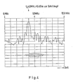
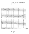
- Fig. 4-9 graphische Darstellungen der Rückstreusignale und
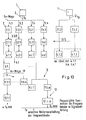
- Fig. 10 ein weiteres Blockschaltdiagramm.
- Zur Herstellung der in den Fig. 4 - 9 dargestellten, zur Weiterverarbeitung bereitgestellten Signale wird die in Fig. 1 dargestellte Schaltung zusammen mit dem in Fig. 2 dargestellten Probengefäß verwendet, wobei der breitbandige Schallkopf die in Fig. 3 dargestellte Leistungscharakteristik aufweist.
- Periodisch wiederholte, elektrische Sendepulse - HF-Bursts - variabler Frequenz fo im Arbeitsbereich fo min...f₀ max (fo min = 0,3 MHz < fo < fo max = 22 MHz) und variabler Bandbreite, gegeben durch die Anzahl n der Sinus-Perioden je Burst: 0,5 < n < 20 mit einstellbarer Amplitude werden von einem Funktionsgenerator 1 erzeugt, der vom zentralen Rechner 15 gesteuert wird. Dieser zentrale Rechner 15 steuert sowohl den Ablauf der Messung als auch deren Auswertung. Der Ausgang 2 des Generators 1 führt zu einem Sende-Empfangs-Schalter 3, der, wie schematisch dargestellt, vom Generator 1 synchronisiert wird. Der S/E Schalter 3 kann auch direkt vom Rechner 15 gesteuert werden. Der Ausgang 2 des S/E Schalters 3 ist mit einem breitbandigen, angepaßten und fokusierten Wandlerelement 4 verbunden. Die besonderen Merkmale dieses Wandlerelementes 4 sind schematisch in Fig. 3 dargestellt. Dieser Wandler weist eine große Breitbandigkeit ohne störende Resonanzen im Arbeitsbereich auf, ferner eine gute elektrische und akustische Impedanzanpassung und eine Transmitter-Mittenfrequenz fT > fo max. Beim beschriebenen Beispiel ist ft = 17 MHz. Dieser Wandler kann auch räumlich und elektrisch getrennte Sende- und Empfangswandlerelemente aufweisen. In diesem Fall wird der S/E Schalter 3 entbehrlich. Mit Vorteil kann zusätzlich ein weiteres Wandlerelement zur Aussendung eines zweiten unabhängigen Hochfrequenzsignals vorgesehen sein.
- Das vom Wandlerelement 4 aufgenommene Signal wird über den umgeschalteten S/E Schalter einem Breitbandvorverstärker 16 zugeführt, dem, bei digitaler Frequenzanalyse, ein Anti-Aliasing-Filter 17 nachgeschaltet ist. Der Breitbandvorverstärker 16 weist eine Bandbreite > fo max auf. Der Filter 17 hat beispielsweise eine Abschneidefrequenz von 10 MHz. Dem Filter 17 ist ein schneller A/D-Wandler nachgeschaltet, in dem das Signal, beispielsweise mit einer Nyquistfrequenz von 12,5 MHz, digitalisiert wird. Die weitere Verarbeitung der Signale erfolgt in einem digitalen Speicheroszilloskop und im zentralen Rechner. Dem A/D Wandler 18 ist ein Plotter 19 nachgeschaltet.
- Fig. 1 zeigt, daß der A/D-Wandler vom Funktionsgenerator 1 getriggert wird.
- Das digitalisierte Signal wird gespeichert und in an sich bekannter Weise weiterverarbeitet. Es steht insbesondere für notwendige Korrekturen zur Verfügung. Vor der A/D-Wandlung kann auch ein Signal abgezweigt werden, das erst nach analoger Weiterverarbeitung digitalisiert wird.
- Fig. 2 zeigt schematisch die Geometrie des Probengefäßes 20, mit dem die im folgenden dargestellten Messergebnisse erzielt wurden.
- Wie Fig. 2 zeigt, ist im Probengefäß 20 der Schallkopf 4 angeordnet. Es handelt sich um einen 17 MHz-Schallkopf, der breitbandig, angepaßt und fokusiert ist. Im Probengefäß 20 befindet sich Wasser. Zwei Folien 21 trennen einen Probenbereich ab, in dem 10 mg Ultraschallkontrastmittel in 3 ml H20 gelöst sind.
- Die im Messbereich zwischen den Folien 21 reflektierten und/oder zurückgestreuten Signale enthalten besondere Anteile, die durch eine Wechselwirkung zwischen dem Sendepuls (bei fo) und dem in das Meßobjekt eingebrachten nichtlinearen Kontrastmittel erhalten wurden.
- Fig. 3 zeigt schematisch das Frequenzband des Wandlerelementes im Schallkopf. Es ist zu erkennen, daß im Arbeitsbereich der Frequenzgang des Schwingers im Schallkopf quasi linear ist. Der Frequenzgang im Arbeitsbereich kann zum Ausgleich eines ähnlichen Frequenzganges im Prüfkörper benutzt werden. Der Frequenzgang im Prüfkörper kann aber auch nachträglich durch eine Gewichtung korrigiert werden.
- Bei der Messung wird im Zeitbereich mittels einer nicht dargestellten, rechnergesteuerten Torschaltung ein interessierender Zeitabschnitt ausgewählt. Es können auch mehrere Zeitabschnitte ausgewählt werden. Mittels einer FFT-Schaltung (Fast Fourier Transformation) wird das zugehörige Spektrum berechnet und Beispiele derartiger Spektren sind in den Fig. 4 - 9 dargestellt. Durch die Wahl einer entsprechenden Zeitfensterlänge kann zwischen optimaler Frequenzauflösung und optimaler Ortsauflösung gewählt werden. In den Fig. 4 - 8 ist jeweils über dem Zeitfenster das Spektrum dargestellt. Um die Spektralkomponenten in diesen Fig. deutlich herauszuheben, wurde ein langes Zeitfenster, d. h. eine schlechte Ortsauflösung gewählt. Fig. 4 veranschaulicht den Zeitverlauf des Sendepulses nach einer Reflektion am Einkoppelfenster ohne Kontrastmittel. fo = 4,0 MHz, + 15 dBm am Schallkopf. Es ist ein deutliches Signal bei 4 MHz zu erkennen. Das im oberen Teil der Fig. 4 dargestellte Signal ist ein gemitteltes Leistungsspektrum, welches hinter dem Tiefpaßfilter mit einer Nyquistfrequenz von 50 MHz erhalten wurde.
- In Fig. 5 ist das Rückstreusignal aus der Probenkammer ohne Ultraschallkontrastmittel dargestellt. Fig. 6 zeigt das Rückstreusignal sieben Minuten nach Zugabe von 10 mg Kontrastmittel in 3 ml H₂O. Es ist ein deutlicher Peak bei 2 x fo zu erkennen.
- Fig. 7 zeigt eine Messung nach 21 Minuten unter den in Fig. 5 dargestellten Bedingungen. Es wurde mit einer Frequenz fo = 3 MHz gearbeitet. Das empfangene Spektrum zeigt deutlich die erste und zweite Harmonische bei 6,0 und 9,0 MHz. Fig. 8 veranschaulicht das Rückstreusignal 15 Minuten nach Zugabe eines Ultraschallkontrastmittels kleinerer Konzentration. Es wurde mit einer Frequenz fo von 4 MHz + 20 dBm am Schallkopf gearbeitet. Das im oberen Teil der Fig. 8 dargestellte Spektrum zeigt mit höherer Frequenzauflösung Subharmonische bei 1/2 fo, Ultraharmonische bei 3/2 fo und die erste Harmonische bei 2 fo.
- Fig. 9 zeigt ein Rückstrahlsignal von linearem Ultraschallkontrastmittel fo = 4 MHz + 15 dBm am Schallkopf. Das Spektrum zeigt nur eine Rückstreuung bei der Anre gungsfrequenz.
- Es ist zu erkennen, daß die dargestellten Spektren deutliche Amplituden in Frequenzbereichen aufweisen, die im Sendespektrum nicht vorkommen, wenn eine Wechselwirkung mit einem nichtlinearen Kontrastmittel erfolgt ist. Es können Spektralveränderungen ausgewertet werden, die durch einen Dopplereffekt bedingt sind. Um die bei den geschilderten Ausführungsbeispielen verwendete Schaltung für bildgebende Ultraschallverfahren zu nutzen, sind zusätzliche Komponenten vorgesehen, falls ein Schallkopf vom Typ "Phased array" oder ein dynamischer fokussierter Schallkopf verwendet werden. Ein derartiges Schaltbild ist in Fig. 10 veranschaulicht.
- Das Sendesignal des Funktionsgenerators 1 (Frequenz fo) wird vom Ausgang 2 dem n-Wege-Signalteiler 5 zugeführt. Die Aufteilung erfolgt auf je einen Zweig pro Wandlerelement. Beim dargestellten Ausführungsbeispiel sind n-Wandler-Elemente 4 vorgesehen. Die Beaufschlagung dieser Wandlerelemente 4.1...4.n erfolgt über die Verzögerungsschaltungen 7.1...7.n und die vom Generator oder Rechner gesteuerten S/E Schalter 3.1...3.n. Die Verzögerungszeiten werden für jedes Wandlerelement vom Rechner so eingestellt, daß bei der gewählten Sendefrequenz die gewünschte Richtcharakteristik am Schallkopf entsteht. Die gleiche Richtcharakteristik wird vom Rechner durch entsprechende Verzögerungen im Empfängerteil eingestellt. Das von den Schallköpfen 4.1...4.n empfangene Signal wird über die S/E Schalter 3.1 Breitbandvorverstärker 6.1, 6.n zugeführt. Jeder Vorverstärker 6.1, ... 6.n beaufschlagt einen m-Wege-Signalteiler 10, dem entsprechend gesteuerte oder eingestellte Verzögerungsschaltungen 11 jeweils nachgeschaltet sind, die Schaltungen 12 zur Frequenzbandselektion speisen. Nachgeschaltet sind Schaltungen zur phasenrichtigen Summation der Frequenzbänder und zur eventuellen Signalaufteilung. Daran schließt sich eine selektive Weiterverarbeitung der einzelnen Frequenzbänder mit den an sich bekannten Verfahren an.
- Insbesondere erfolgt eine Auswertung der Frequenzen, die mit fo nicht identisch sind, beispielsweise 1/2 fo, 2 fo.
- Die Verzögerungsschaltungen können variabel oder fest sein. Die Verteilung der empfangenen Signale auf m-Wege-Signalteiler erzeugt die gewünschte Zahl von Frequenzbändern, deren Lage und Breite mit Bandfiltern eingestellt werden. Alternativ kann die Aufteilung auch so erfolgen, daß das Empfangssignal mit einem vom Sendesignal abgeleiteten, je nach Frequenzband verschiedenen Hilfssignal so gemischt wird, daß die einzelnen Bänder in den Folgestufen mit einheitlichen Komponenten arbeiten können.
- Das Frequenzband um fo liefert die üblichen Ergebnisse, während die anderen Bänder stark frequenzverschobene und nichtlineare Signalanteile aus Wechselwirkungen des Sendesignals mit den nichtlinearen Ultraschallkontrastmitteln enthalten.
- Die weiteren Verarbeitungsschritte und Signalanalysen könnten in jedem beliebigen Frequenzkanal oder in mehreren parallelen Frequenzkanälen nach den bekannten Verfahren erfolgen.
- Um zwei Sendefrequenzen fo und fp zu verwenden, ist der auf der rechten Seite der Fig. 10 dargestellte, zweite Generator vorgesehen, der über Signalteiler und Verzögerungsleitungen 15 an die S/E Schalter 3.1...3.n angeschlossen ist. Der zweite Generator 1 ermöglicht, min destens den Raumbereich im Prüfobjekt zu beschallen, der durch die momentane Richtcharakteristik und das Empfangstor festgelegt wird. Der Aufbau kann derart sein, daß zusätzlich zu den beschriebenen breitbandigen Wandlerelementen sich im Schallkopf noch mindestens ein ebenfalls breitbandiger Sendewandler befindet, der vorzugsweise elektrisch von den übrigen getrennt ist und der von dem zweiten, unabhängigen Sendegenerator 1 gespeist wird. Die beiden Sendesignale können aber auch elektrisch so überlagert werden, daß die gleichen Wandlerelemente benutzt werden können.
Claims (17)
in das zu beschallende Untersuchungsgebiet ein Material eingebracht wird, mit dem in diesem Gebiet nichtlineare Schwingungen durch eingestrahlte Ultraschallwellen erzeugt werden,
ein breitbandiger, akustisch hochbedämpfter, elektrisch angepaßter Ultraschallwandler mit einem oder mehreren, einzeln oder in Gruppen zusammengefaßte ansteuerbare Wandlerelemente, der auf ein Frequenzband anspricht, das, außer der Anregungsfrequenz wenigstens das


und
aus dem vom Ultraschallwandler empfangenen, aus dem Untersuchungsgebiet reflektierten oder aus diesem zurückgestreute Ultraschallsignal die Anregungsfrequenz und/oder mindestens eine von deren


in das zu beschallende Untersuchungsgebiet ein Material eingebracht wird, mit dem in diesem Gebiet nichtlineare Schwingungen durch eingestrahlte Ultraschallwellen erzeugt werden,
ein breitbandig, akustisch hochbedämpfter, elektrisch angepaßter Ultraschallwandler mit einem oder mehreren, einzeln oder in Gruppen zusammengefaßt, ansteuerbaren Wandlerelementen, mittels zweier HF-Bursts angeregt wird, deren jeweilige Anregungsfrequenz voneinander verschieden und kleiner als die Hälfte der Frequenzobergrenze des Arbeitsbereichs ist,
und
aus dem vom Ultraschallwandler empfangenen, aus dem Untersuchungsgebiet reflektierten oder aus diesem zurückgestreuten Ultraschallsignalen Signalkombinationen der beiden Anregungsfrequenzen, insbesondere deren Summenfrequenz ausgewertet werden.
dadurch gekennzeichnet, daß
das Material nichtlineare Schwingungen erzeugende Streukörper enthält.
dadurch gekennzeichnet, daß
das Material ein Ultraschallkontrastmittel in Form einer Lösung, Emulsion oder Suspension ist.
dadurch gekennzeichnet, daß
das Material Mikrobläschen oder Mikrobläschen erzeugende Mittel sind.
dadurch gekennzeichnet, daß
eine Mikrobläschen-Suspension mit einer Konzentration von 10⁻³ Gew% bis 30 Gew% Trockensubstanz im Suspensionsmedium eingebracht wird.
dadurch gekennzeichnet, daß
der Ultraschallwandler mittels mindestens eines Funktionsgenerators angeregt wird, mit dem HF-Bursts einstellbarer Amplitude und einstellbarer Anregungsfrequenz (fo) im Bereich von 0,3 MHz bis 22 MHz, vorzugsweise 1 MHz bis 11 MHz und mit 0,5 bis 20, vorzugsweise 1 bis 5 Perioden erzeugt werden.
dadurch gekennzeichnet, daß
Frequenzen ausgewertet werden, die kleiner sind als die Ultraschallwandler-Mittenfrequenz (fT).
dadurch gekennzeichnet, daß
bei der Auswertung mittels einer rechnergesteuerten Torschaltung wenigstens ein Zeitabschnitt ausgewählt und das zugehörige Frequenzspektrum analog oder digital bestimmt wird.
dadurch gekennzeichnet, daß
die Zeitfensterlänge und Anzahl der Perioden pro Burst je nach gewünschter Frequenzauflösung und Ortsauflösung eingestellt wird.
gekennzeichnet durch
gekennzeichnet durch
dadurch gekennzeichnet, daß
die vom Ultraschallwandler abgestrahlte Schallintensität als Funktion der Frequenz im Frequenzbereich unterhalb der Ultraschallwandler-Mittenfrequenz (fT) eine positive erste Ableitung nach der Frequenz aufweist, die insbesondere im Arbeitsbereich (fo min < fo < fo max < fT) konstant ist oder daß diese Schallintensität in diesem Frequenzbereich einen konstanten Wert hat.
gekennzeichnet durch
dadurch gekennzeichnet, daß
die zwei HF-Bursts von zwei Funktionsgeneratoren erzeugt und entweder einem Ultraschallwandlerelement oder zwei Ultraschallwandlerelementen zugeführt werden, und daß mit jedem Funktionsgenerator HF-Bursts einstellbarer Amplitude und einstellbarer Mittenfrequenz (fo) im Bereich von 0,5 bis 20 MHz, vorzugsweise 1 bis 5 MHz mit 1 bis 25, insbesondere 1 bis 10 Perioden erzeugt werden.
gekennzeichnet durch
einen zweiten Funktionsgenerator der entweder über den S/E Schalter (3) mit dem Eingang eines Ultraschallwandlerelementes oder direkt mit dem Eingang eines zusätzlichen Wandlerelementes verbunden ist.
gekennzeichnet durch
einen zweiten Funktionsgenerator (1), der über einen n-Wege-Signalteiler auf die n Verzögerungsschaltungn (7.1.1-7.n.1) aufschaltbar ist.
Priority Applications (1)
| Application Number | Priority Date | Filing Date | Title |
|---|---|---|---|
| AT89250017T ATE68887T1 (de) | 1988-09-01 | 1989-08-23 | Ultraschallverfahren und schaltungen zu deren durchfuehrung. |
Applications Claiming Priority (2)
| Application Number | Priority Date | Filing Date | Title |
|---|---|---|---|
| DE3829999A DE3829999A1 (de) | 1988-09-01 | 1988-09-01 | Ultraschallverfahren und schaltungen zu deren durchfuehrung |
| DE3829999 | 1988-09-01 |
Publications (2)
| Publication Number | Publication Date |
|---|---|
| EP0357164A1 true EP0357164A1 (de) | 1990-03-07 |
| EP0357164B1 EP0357164B1 (de) | 1991-10-23 |
Family
ID=6362240
Family Applications (1)
| Application Number | Title | Priority Date | Filing Date |
|---|---|---|---|
| EP89250017A Expired - Lifetime EP0357164B1 (de) | 1988-09-01 | 1989-08-23 | Ultraschallverfahren und Schaltungen zu deren Durchführung |
Country Status (13)
| Country | Link |
|---|---|
| US (4) | US6064628A (de) |
| EP (1) | EP0357164B1 (de) |
| JP (1) | JP2677888B2 (de) |
| KR (1) | KR0138901B1 (de) |
| AT (1) | ATE68887T1 (de) |
| AU (1) | AU637059B2 (de) |
| CA (1) | CA1338175C (de) |
| DE (2) | DE3829999A1 (de) |
| DK (1) | DK175571B1 (de) |
| ES (1) | ES2027062T3 (de) |
| GR (1) | GR3003632T3 (de) |
| WO (1) | WO1990002517A1 (de) |
| ZA (1) | ZA896738B (de) |
Cited By (38)
| Publication number | Priority date | Publication date | Assignee | Title |
|---|---|---|---|---|
| US5540909A (en) * | 1994-09-28 | 1996-07-30 | Alliance Pharmaceutical Corp. | Harmonic ultrasound imaging with microbubbles |
| WO1996013213A3 (de) * | 1994-11-01 | 1996-08-01 | Schering Ag | Ultraschallverfahren und schaltungen zur durchführung dieser verfahren |
| US5628322A (en) * | 1995-05-15 | 1997-05-13 | Kabushiki Kaisha Toshiba | Method of ultrasound imaging and diagnostic ultrasound system |
| US5724976A (en) * | 1994-12-28 | 1998-03-10 | Kabushiki Kaisha Toshiba | Ultrasound imaging preferable to ultrasound contrast echography |
| US5833614A (en) * | 1997-07-15 | 1998-11-10 | Acuson Corporation | Ultrasonic imaging method and apparatus for generating pulse width modulated waveforms with reduced harmonic response |
| US5846202A (en) * | 1996-07-30 | 1998-12-08 | Acuson Corporation | Ultrasound method and system for imaging |
| US5860931A (en) * | 1997-10-10 | 1999-01-19 | Acuson Corporation | Ultrasound method and system for measuring perfusion |
| US5873830A (en) * | 1997-08-22 | 1999-02-23 | Acuson Corporation | Ultrasound imaging system and method for improving resolution and operation |
| US5873829A (en) * | 1996-01-29 | 1999-02-23 | Kabushiki Kaisha Toshiba | Diagnostic ultrasound system using harmonic echo imaging |
| US5882306A (en) * | 1997-04-11 | 1999-03-16 | Acuson Corporation | Ultrasound imaging methods and systems |
| US5897500A (en) * | 1997-12-18 | 1999-04-27 | Acuson Corporation | Ultrasonic imaging system and method for displaying composite fundamental and harmonic images |
| US5913823A (en) * | 1997-07-15 | 1999-06-22 | Acuson Corporation | Ultrasound imaging method and system for transmit signal generation for an ultrasonic imaging system capable of harmonic imaging |
| US5924991A (en) * | 1997-08-22 | 1999-07-20 | Acuson Corporation | Ultrasonic system and method for harmonic imaging in three dimensions |
| US5935069A (en) * | 1997-10-10 | 1999-08-10 | Acuson Corporation | Ultrasound system and method for variable transmission of ultrasonic signals |
| US5944666A (en) * | 1997-08-21 | 1999-08-31 | Acuson Corporation | Ultrasonic method for imaging blood flow including disruption or activation of contrast agent |
| US5957845A (en) * | 1997-04-11 | 1999-09-28 | Acuson Corporation | Gated ultrasound imaging apparatus and method |
| US5957852A (en) * | 1998-06-02 | 1999-09-28 | Acuson Corporation | Ultrasonic harmonic imaging system and method |
| US5961460A (en) * | 1997-04-11 | 1999-10-05 | Acuson Corporation | Ultrasound imaging enhancement methods and systems |
| US6005827A (en) * | 1995-03-02 | 1999-12-21 | Acuson Corporation | Ultrasonic harmonic imaging system and method |
| US6009046A (en) * | 1995-03-02 | 1999-12-28 | Acuson Corporation | Ultrasonic harmonic imaging system and method |
| US6023977A (en) * | 1997-08-01 | 2000-02-15 | Acuson Corporation | Ultrasonic imaging aberration correction system and method |
| US6027448A (en) * | 1995-03-02 | 2000-02-22 | Acuson Corporation | Ultrasonic transducer and method for harmonic imaging |
| US6030344A (en) * | 1996-12-04 | 2000-02-29 | Acuson Corporation | Methods and apparatus for ultrasound image quantification |
| US6039690A (en) * | 1997-06-17 | 2000-03-21 | Acuson Corporation | Method and apparatus for frequency control of an ultrasound system |
| US6104670A (en) * | 1995-03-02 | 2000-08-15 | Acuson Corporation | Ultrasonic harmonic imaging system and method |
| US6106465A (en) * | 1997-08-22 | 2000-08-22 | Acuson Corporation | Ultrasonic method and system for boundary detection of an object of interest in an ultrasound image |
| US6122222A (en) * | 1995-03-02 | 2000-09-19 | Acuson Corporation | Ultrasonic transmit and receive system |
| US6132374A (en) * | 1997-08-01 | 2000-10-17 | Acuson Corporation | Ultrasonic imaging method and system |
| US6193659B1 (en) | 1997-07-15 | 2001-02-27 | Acuson Corporation | Medical ultrasonic diagnostic imaging method and apparatus |
| EP0995130A4 (de) * | 1997-07-15 | 2001-03-21 | Acuson | Harmonisches ultraschallbilderzeugungssystem und verfahren |
| US6222948B1 (en) | 1996-02-29 | 2001-04-24 | Acuson Corporation | Multiple ultrasound image registration system, method and transducer |
| US6258339B1 (en) | 1993-07-30 | 2001-07-10 | Alliance Pharmaceutical Corp. | Osmotically stabilized microbubble preparations |
| US6280705B1 (en) | 1993-07-30 | 2001-08-28 | Alliance Pharmaceutical Corp. | Kits & systems for ultrasonic imaging |
| EP0947853A3 (de) * | 1998-03-31 | 2003-01-08 | General Electric Company | Verfahren und Anlage zur verbesserten Ultraschall-B-Bild-Strombilderzeugung |
| EP0770352B1 (de) * | 1995-10-10 | 2004-12-29 | Advanced Technology Laboratories, Inc. | Ultraschall-Bilderzeugung zur Diagnostik mittels Kontrastmitteln |
| US6905467B2 (en) | 1997-08-15 | 2005-06-14 | Acuson Corporation | Ultrasonic harmonic imaging system and method using waveform pre-distortion |
| EP0851241B1 (de) * | 1996-11-26 | 2006-05-24 | ATL Ultrasound, Inc. | Diagnostik-Bilderzeugung mittels Ultraschall unterschiedlicher Sende- und Empfangsfrequenz |
| US8658205B2 (en) | 1998-01-14 | 2014-02-25 | Lantheus Medical Imaging, Inc. | Preparation of a lipid blend and a phospholipid suspension containing the lipid blend |
Families Citing this family (42)
| Publication number | Priority date | Publication date | Assignee | Title |
|---|---|---|---|---|
| DE3829999A1 (de) * | 1988-09-01 | 1990-03-15 | Schering Ag | Ultraschallverfahren und schaltungen zu deren durchfuehrung |
| US20020150539A1 (en) | 1989-12-22 | 2002-10-17 | Unger Evan C. | Ultrasound imaging and treatment |
| US5542935A (en) | 1989-12-22 | 1996-08-06 | Imarx Pharmaceutical Corp. | Therapeutic delivery systems related applications |
| US6088613A (en) | 1989-12-22 | 2000-07-11 | Imarx Pharmaceutical Corp. | Method of magnetic resonance focused surgical and therapeutic ultrasound |
| US6551576B1 (en) | 1989-12-22 | 2003-04-22 | Bristol-Myers Squibb Medical Imaging, Inc. | Container with multi-phase composition for use in diagnostic and therapeutic applications |
| US5585112A (en) | 1989-12-22 | 1996-12-17 | Imarx Pharmaceutical Corp. | Method of preparing gas and gaseous precursor-filled microspheres |
| US5205290A (en) | 1991-04-05 | 1993-04-27 | Unger Evan C | Low density microspheres and their use as contrast agents for computed tomography |
| US5874062A (en) | 1991-04-05 | 1999-02-23 | Imarx Pharmaceutical Corp. | Methods of computed tomography using perfluorocarbon gaseous filled microspheres as contrast agents |
| US5255683A (en) | 1991-12-30 | 1993-10-26 | Sound Science Limited Partnership | Methods of and systems for examining tissue perfusion using ultrasonic contrast agents |
| DE4330148A1 (de) * | 1993-09-07 | 1995-03-09 | Merk Electronic Gmbh | Verfahren zur dreidimensionalen Ultraschall-Druchleuchtung |
| US7083572B2 (en) | 1993-11-30 | 2006-08-01 | Bristol-Myers Squibb Medical Imaging, Inc. | Therapeutic delivery systems |
| US6521211B1 (en) | 1995-06-07 | 2003-02-18 | Bristol-Myers Squibb Medical Imaging, Inc. | Methods of imaging and treatment with targeted compositions |
| CA2252617A1 (en) | 1996-05-01 | 1997-11-06 | Imarx Pharmaceutical Corp. | Methods for delivering compounds into a cell |
| JPH105216A (ja) * | 1996-06-19 | 1998-01-13 | Ge Yokogawa Medical Syst Ltd | 超音波撮像方法および装置並びに造影剤 |
| US6414139B1 (en) | 1996-09-03 | 2002-07-02 | Imarx Therapeutics, Inc. | Silicon amphiphilic compounds and the use thereof |
| US5846517A (en) | 1996-09-11 | 1998-12-08 | Imarx Pharmaceutical Corp. | Methods for diagnostic imaging using a renal contrast agent and a vasodilator |
| US6086539A (en) * | 1996-12-04 | 2000-07-11 | Acuson Corporation | Methods and apparatus for ultrasound image quantification |
| US6090800A (en) | 1997-05-06 | 2000-07-18 | Imarx Pharmaceutical Corp. | Lipid soluble steroid prodrugs |
| US6537246B1 (en) | 1997-06-18 | 2003-03-25 | Imarx Therapeutics, Inc. | Oxygen delivery agents and uses for the same |
| US6120751A (en) | 1997-03-21 | 2000-09-19 | Imarx Pharmaceutical Corp. | Charged lipids and uses for the same |
| US7452551B1 (en) | 2000-10-30 | 2008-11-18 | Imarx Therapeutics, Inc. | Targeted compositions for diagnostic and therapeutic use |
| US6416740B1 (en) | 1997-05-13 | 2002-07-09 | Bristol-Myers Squibb Medical Imaging, Inc. | Acoustically active drug delivery systems |
| US6548047B1 (en) | 1997-09-15 | 2003-04-15 | Bristol-Myers Squibb Medical Imaging, Inc. | Thermal preactivation of gaseous precursor filled compositions |
| JP3976897B2 (ja) * | 1998-01-28 | 2007-09-19 | 株式会社日立メディコ | 超音波装置 |
| US6048316A (en) * | 1998-10-16 | 2000-04-11 | Acuson Corporation | Medical diagnostic ultrasonic imaging system and method for displaying composite fundamental and harmonic images |
| US6400310B1 (en) * | 1998-10-22 | 2002-06-04 | Washington University | Method and apparatus for a tunable high-resolution spectral estimator |
| US6494841B1 (en) * | 2000-02-29 | 2002-12-17 | Acuson Corporation | Medical diagnostic ultrasound system using contrast pulse sequence imaging |
| US6425869B1 (en) * | 2000-07-18 | 2002-07-30 | Koninklijke Philips Electronics, N.V. | Wideband phased-array transducer for uniform harmonic imaging, contrast agent detection, and destruction |
| US6951542B2 (en) | 2002-06-26 | 2005-10-04 | Esaote S.P.A. | Method and apparatus for ultrasound imaging of a biopsy needle or the like during an ultrasound imaging examination |
| US6872180B2 (en) * | 2002-03-28 | 2005-03-29 | Schering Ag | Device and process for quantifying bodies by means of ultrasound |
| AU2003284096A1 (en) | 2002-10-10 | 2004-05-04 | Visualsonics Inc. | High frequency high frame-rate ultrasound imaging system |
| ITFI20030077A1 (it) * | 2003-03-26 | 2004-09-27 | Actis Active Sensors S R L | Metodo per l'indagine ecografica tramite mezzi di contrasto |
| US6960169B2 (en) * | 2003-05-19 | 2005-11-01 | Siemens Medical Solutions Usa, Inc. | Spread spectrum coding for ultrasound contrast agent imaging |
| WO2005104210A2 (en) * | 2004-04-20 | 2005-11-03 | Visualsonics Inc. | Arrayed ultrasonic transducer |
| JP5038289B2 (ja) * | 2005-03-11 | 2012-10-03 | コーニンクレッカ フィリップス エレクトロニクス エヌ ヴィ | 位相収差訂正のためのマイクロバブル生成技術 |
| CA2628100C (en) | 2005-11-02 | 2016-08-23 | Visualsonics Inc. | High frequency array ultrasound system |
| JP5154554B2 (ja) | 2006-08-01 | 2013-02-27 | ボストン サイエンティフィック サイムド,インコーポレイテッド | 非線形イメージングのためのパルスインバージョンシーケンス |
| US8316518B2 (en) * | 2008-09-18 | 2012-11-27 | Visualsonics Inc. | Methods for manufacturing ultrasound transducers and other components |
| US9184369B2 (en) | 2008-09-18 | 2015-11-10 | Fujifilm Sonosite, Inc. | Methods for manufacturing ultrasound transducers and other components |
| US9173047B2 (en) | 2008-09-18 | 2015-10-27 | Fujifilm Sonosite, Inc. | Methods for manufacturing ultrasound transducers and other components |
| KR102052257B1 (ko) * | 2018-01-04 | 2019-12-04 | 재단법인 다차원 스마트 아이티 융합시스템 연구단 | 송수신 가능한 초음파 시스템 및 그 방법 |
| CN116113825A (zh) * | 2020-07-01 | 2023-05-12 | 深视超声科技公司 | 具有光学传感器的声光谐波成像 |
Citations (4)
| Publication number | Priority date | Publication date | Assignee | Title |
|---|---|---|---|---|
| US3640271A (en) * | 1969-06-30 | 1972-02-08 | Ibm | Blood flow pressure measurement technique employing injected bubbled and ultrasonic frequency scanning |
| EP0064399A2 (de) * | 1981-04-30 | 1982-11-10 | Fujitsu Limited | Ultraschallmessmethode |
| EP0072330A2 (de) * | 1981-08-08 | 1983-02-16 | Fujitsu Limited | Druckmesssystem mit Ultraschallwellen |
| EP0147955A2 (de) * | 1983-12-02 | 1985-07-10 | Fujitsu Limited | System zur Messung eines nichtlinearen Parameters mittel Ultraschall |
Family Cites Families (57)
| Publication number | Priority date | Publication date | Assignee | Title |
|---|---|---|---|---|
| US34566A (en) * | 1862-03-04 | Machine for | ||
| US3156110A (en) * | 1962-07-23 | 1964-11-10 | Manfred E Clynes | Ultrasonic detection and visualization of internal structure |
| US3510833A (en) * | 1967-01-09 | 1970-05-05 | Vitro Corp Of America | Frequency conversion imaging system |
| US3444509A (en) * | 1967-07-03 | 1969-05-13 | Gen Dynamics Corp | Sonar system |
| GB1268640A (en) * | 1968-05-31 | 1972-03-29 | Nat Res Dev | Acoustic detection apparatus |
| US3763463A (en) * | 1972-09-21 | 1973-10-02 | Us Navy | Shrapnel sonar |
| US3812454A (en) * | 1973-01-02 | 1974-05-21 | Trw Inc | Low frequency parametric acousto-optical imaging method and apparatus |
| US3964013A (en) * | 1974-10-22 | 1976-06-15 | The United States Of America As Represented By The Secretary Of The Navy | Cavitating parametric underwater acoustic source |
| AU499252B2 (en) * | 1975-05-01 | 1979-04-12 | Commonwealth Of Australia, The | Apparatus for ultrasonic examination |
| US4063549A (en) * | 1975-12-22 | 1977-12-20 | Technicon Instruments Corporation | Ultrasonic method and apparatus for imaging and characterization of bodies |
| US4068521A (en) * | 1976-07-22 | 1978-01-17 | Renal Systems, Inc. | Ultrasonic air and blood foam detector |
| GB1570687A (en) * | 1976-11-04 | 1980-07-09 | Nat Res Dev | Ultrasonic phase array systems |
| US4075599A (en) * | 1976-11-30 | 1978-02-21 | The International Nickel Company, Inc. | Undersea geophysical exploration |
| US4154113A (en) * | 1978-05-24 | 1979-05-15 | General Electric Company | Ultrasonic imaging system |
| FR2441180A1 (fr) * | 1978-11-10 | 1980-06-06 | Thomson Csf | Courantometre doppler pour grands fonds |
| US4276885A (en) | 1979-05-04 | 1981-07-07 | Rasor Associates, Inc | Ultrasonic image enhancement |
| US4265251A (en) * | 1979-06-28 | 1981-05-05 | Rasor Associates, Inc. | Method of determining pressure within liquid containing vessel |
| JPS57203434A (en) * | 1981-06-08 | 1982-12-13 | Tokyo Shibaura Electric Co | Ultrasonic diagnostic apparatus |
| JPS58132677A (ja) * | 1982-02-03 | 1983-08-08 | Hitachi Medical Corp | 超音波撮像装置 |
| US4454884A (en) * | 1982-09-27 | 1984-06-19 | Advanced Technology Laboratories, Inc. | Wide dynamic range ultrasound echo receiver |
| US4572203A (en) * | 1983-01-27 | 1986-02-25 | Feinstein Steven B | Contact agents for ultrasonic imaging |
| US4718433A (en) * | 1983-01-27 | 1988-01-12 | Feinstein Steven B | Contrast agents for ultrasonic imaging |
| JPS59164956A (ja) * | 1983-03-10 | 1984-09-18 | Fujitsu Ltd | 超音波媒体の等価非線形パラメ−タ分布測定装置 |
| US4532812A (en) * | 1983-06-30 | 1985-08-06 | Nl Industries, Inc. | Parametric acoustic flow meter |
| US4747411A (en) | 1984-03-28 | 1988-05-31 | National Biochemical Research Foundation | Three-dimensional imaging system |
| JPS6111025A (ja) * | 1984-06-26 | 1986-01-18 | 株式会社東芝 | 超音波組織診断装置 |
| US4621645A (en) * | 1984-09-14 | 1986-11-11 | General Electric Company | Method of estimating tissue attenuation using wideband ultrasonic pulse and apparatus for use therein |
| JPS61100237A (ja) * | 1984-10-23 | 1986-05-19 | 株式会社東芝 | 超音波診断装置 |
| JPS61228843A (ja) * | 1985-04-04 | 1986-10-13 | アロカ株式会社 | 超音波計測方法及び装置 |
| US4653328A (en) * | 1985-04-24 | 1987-03-31 | North American Philips Corporation | Method and apparatus for echo-ultrasound imaging using compound AM-FM detection with increased dynamic range |
| JPH074364B2 (ja) * | 1986-01-28 | 1995-01-25 | 株式会社東芝 | 超音波診断装置 |
| US4807633A (en) * | 1986-05-21 | 1989-02-28 | Indianapolis Center For Advanced Research | Non-invasive tissue thermometry system and method |
| DE3637926C1 (de) * | 1986-11-05 | 1987-11-26 | Schering Ag | Ultraschall-Manometrieverfahren in einer Fluessigkeit mittels Mikroblaeschen |
| JPS63150683A (ja) * | 1986-12-16 | 1988-06-23 | Fuji Electric Co Ltd | 超音波送受波整合器 |
| US4881549A (en) * | 1987-05-29 | 1989-11-21 | Marquette Electronics | Apparatus and method for obtaining ultrasonic backcatter measurement from tissue |
| JPH01299537A (ja) * | 1988-05-27 | 1989-12-04 | Agency Of Ind Science & Technol | 音響特性測定装置及び測温装置 |
| US4862892A (en) * | 1988-07-18 | 1989-09-05 | Sri International | Ultrasonic reflex transmission imaging method and apparatus with artifact removal |
| US5410516A (en) * | 1988-09-01 | 1995-04-25 | Schering Aktiengesellschaft | Ultrasonic processes and circuits for performing them |
| DE3829999A1 (de) * | 1988-09-01 | 1990-03-15 | Schering Ag | Ultraschallverfahren und schaltungen zu deren durchfuehrung |
| FR2643252B1 (fr) * | 1989-02-21 | 1991-06-07 | Technomed Int Sa | Appareil de destruction selective de cellules incluant les tissus mous et les os a l'interieur du corps d'un etre vivant par implosion de bulles de gaz |
| US5255683A (en) * | 1991-12-30 | 1993-10-26 | Sound Science Limited Partnership | Methods of and systems for examining tissue perfusion using ultrasonic contrast agents |
| US5567415A (en) * | 1993-05-12 | 1996-10-22 | The Board Of Regents Of The University Of Nebraska | Ultrasound contrast agents and methods for their manufacture and use |
| US5526816A (en) * | 1994-09-22 | 1996-06-18 | Bracco Research S.A. | Ultrasonic spectral contrast imaging |
| US5540909A (en) * | 1994-09-28 | 1996-07-30 | Alliance Pharmaceutical Corp. | Harmonic ultrasound imaging with microbubbles |
| US5678553A (en) * | 1994-11-01 | 1997-10-21 | Schering Aktiengesellschaft | Ultrasonic processes and circuits for carrying out those processes |
| US5608690A (en) * | 1995-03-02 | 1997-03-04 | Acuson Corporation | Transmit beamformer with frequency dependent focus |
| US5560364A (en) * | 1995-05-12 | 1996-10-01 | The Board Of Regents Of The University Of Nebraska | Suspended ultra-sound induced microbubble cavitation imaging |
| US5601086A (en) * | 1995-05-12 | 1997-02-11 | The United States Of America As Represented By The Administrator Of The National Aeronautics And Space Administration | Beat frequency ultrasonic microsphere contrast agent detection system |
| JP3865800B2 (ja) * | 1995-05-15 | 2007-01-10 | 株式会社東芝 | 超音波診断装置 |
| US5558092A (en) * | 1995-06-06 | 1996-09-24 | Imarx Pharmaceutical Corp. | Methods and apparatus for performing diagnostic and therapeutic ultrasound simultaneously |
| US5601085A (en) * | 1995-10-02 | 1997-02-11 | Nycomed Imaging As | Ultrasound imaging |
| US5833613A (en) * | 1996-09-27 | 1998-11-10 | Advanced Technology Laboratories, Inc. | Ultrasonic diagnostic imaging with contrast agents |
| JP3580627B2 (ja) * | 1996-01-29 | 2004-10-27 | 株式会社東芝 | 超音波診断装置 |
| US5846202A (en) * | 1996-07-30 | 1998-12-08 | Acuson Corporation | Ultrasound method and system for imaging |
| US5752515A (en) * | 1996-08-21 | 1998-05-19 | Brigham & Women's Hospital | Methods and apparatus for image-guided ultrasound delivery of compounds through the blood-brain barrier |
| US5833614A (en) * | 1997-07-15 | 1998-11-10 | Acuson Corporation | Ultrasonic imaging method and apparatus for generating pulse width modulated waveforms with reduced harmonic response |
| US5860931A (en) * | 1997-10-10 | 1999-01-19 | Acuson Corporation | Ultrasound method and system for measuring perfusion |
-
1988
- 1988-09-01 DE DE3829999A patent/DE3829999A1/de active Granted
-
1989
- 1989-08-23 AT AT89250017T patent/ATE68887T1/de not_active IP Right Cessation
- 1989-08-23 AU AU41824/89A patent/AU637059B2/en not_active Expired
- 1989-08-23 KR KR1019900700928A patent/KR0138901B1/ko not_active Expired - Lifetime
- 1989-08-23 DE DE8989250017T patent/DE58900401D1/de not_active Expired - Lifetime
- 1989-08-23 JP JP1508941A patent/JP2677888B2/ja not_active Expired - Lifetime
- 1989-08-23 EP EP89250017A patent/EP0357164B1/de not_active Expired - Lifetime
- 1989-08-23 ES ES198989250017T patent/ES2027062T3/es not_active Expired - Lifetime
- 1989-08-23 WO PCT/DE1989/000560 patent/WO1990002517A1/de not_active Ceased
- 1989-08-31 CA CA000610016A patent/CA1338175C/en not_active Expired - Lifetime
- 1989-09-01 ZA ZA896738A patent/ZA896738B/xx unknown
-
1991
- 1991-02-22 DK DK199100316A patent/DK175571B1/da not_active IP Right Cessation
-
1992
- 1992-01-23 GR GR910401550T patent/GR3003632T3/el unknown
-
1995
- 1995-06-06 US US08/467,886 patent/US6064628A/en not_active Expired - Lifetime
-
1999
- 1999-01-12 US US09/228,972 patent/US6034922A/en not_active Expired - Fee Related
- 1999-11-02 US US09/432,123 patent/US6221017B1/en not_active Expired - Fee Related
-
2000
- 2000-12-20 US US09/740,054 patent/US6443899B2/en not_active Expired - Fee Related
Patent Citations (4)
| Publication number | Priority date | Publication date | Assignee | Title |
|---|---|---|---|---|
| US3640271A (en) * | 1969-06-30 | 1972-02-08 | Ibm | Blood flow pressure measurement technique employing injected bubbled and ultrasonic frequency scanning |
| EP0064399A2 (de) * | 1981-04-30 | 1982-11-10 | Fujitsu Limited | Ultraschallmessmethode |
| EP0072330A2 (de) * | 1981-08-08 | 1983-02-16 | Fujitsu Limited | Druckmesssystem mit Ultraschallwellen |
| EP0147955A2 (de) * | 1983-12-02 | 1985-07-10 | Fujitsu Limited | System zur Messung eines nichtlinearen Parameters mittel Ultraschall |
Non-Patent Citations (2)
| Title |
|---|
| JOURNAL OF THE ACOUSTICAL SOCIETY OF AMERICA. vol. 69, no. 4, April 1981, NEW YORK US Seiten 1210 - 1212; W.K.Law et al.: "Ultrasonic determination of the nonlinearity parameter B/A for biological media" & "METHODS" * |
| JOURNAL OF THE ACOUSTICAL SOCIETY OF AMERICA. vol. 83, no. 3, März 1988, NEW YORK US Seiten 942 - 949; L.Germain et al.: "Generation and detection of high-order harmonics in liquids using a scanning acoustic microscope" * |
Cited By (70)
| Publication number | Priority date | Publication date | Assignee | Title |
|---|---|---|---|---|
| US6287539B1 (en) | 1993-07-30 | 2001-09-11 | Alliance Pharmaceuticals Corp. | Methods of imaging using osmotically stabilized microbubble preparations |
| US6258339B1 (en) | 1993-07-30 | 2001-07-10 | Alliance Pharmaceutical Corp. | Osmotically stabilized microbubble preparations |
| US6280705B1 (en) | 1993-07-30 | 2001-08-28 | Alliance Pharmaceutical Corp. | Kits & systems for ultrasonic imaging |
| US6280704B1 (en) | 1993-07-30 | 2001-08-28 | Alliance Pharmaceutical Corp. | Ultrasonic imaging system utilizing a long-persistence contrast agent |
| US6939531B2 (en) | 1993-07-30 | 2005-09-06 | Imcor Pharmaceutical Company | Ultrasonic imaging system utilizing a long-persistence contrast agent |
| US6953569B2 (en) | 1993-07-30 | 2005-10-11 | Imcor Pharmaceutical Company | Mixed gas microbubble compositions |
| US6372195B1 (en) | 1993-07-30 | 2002-04-16 | Alliance Pharmaceutical Corp. | Mixed gas microbubble compositions |
| US7005120B2 (en) | 1993-07-30 | 2006-02-28 | Imcor Pharmaceutical Company | Osmotically stabilized microbubble preparations |
| US6706253B2 (en) | 1993-07-30 | 2004-03-16 | Ernest G. Schutt | Osmotically stabilized microbubble preparations |
| US7141235B2 (en) | 1993-07-30 | 2006-11-28 | Imcor Pharmaceutical Co. | Stabilized gas emulsion containing phospholipid for ultrasound contrast enhancement |
| US7374744B2 (en) | 1994-09-28 | 2008-05-20 | Imcor Pharmaceutical Co. | Harmonic ultrasound imaging with microbubbles |
| US5733527A (en) * | 1994-09-28 | 1998-03-31 | Alliance Pharmaceutical Corp. | Methods for harmonic imaging with ultrasound |
| US6056943A (en) * | 1994-09-28 | 2000-05-02 | Alliance Pharmaceutical Corp. | Methods of ultrasound imaging using phospholipid stabilized microbubbles |
| US6036644A (en) * | 1994-09-28 | 2000-03-14 | Alliance Pharmaceutical Corp. | Enhanced methods of ultrasound imaging using multiple frequencies |
| US6019960A (en) * | 1994-09-28 | 2000-02-01 | Alliance Pharmaceutical Corp. | Systems for harmonic ultrasound imaging |
| US5540909A (en) * | 1994-09-28 | 1996-07-30 | Alliance Pharmaceutical Corp. | Harmonic ultrasound imaging with microbubbles |
| WO1996013213A3 (de) * | 1994-11-01 | 1996-08-01 | Schering Ag | Ultraschallverfahren und schaltungen zur durchführung dieser verfahren |
| AU698398B2 (en) * | 1994-11-01 | 1998-10-29 | Bayer Intellectual Property Gmbh | Ultrasonic processes and circuits for carrying out those processes |
| US5724976A (en) * | 1994-12-28 | 1998-03-10 | Kabushiki Kaisha Toshiba | Ultrasound imaging preferable to ultrasound contrast echography |
| US6222795B1 (en) | 1995-03-02 | 2001-04-24 | Acuson Corporation | Ultrasonic harmonic imaging system and method |
| US6027448A (en) * | 1995-03-02 | 2000-02-22 | Acuson Corporation | Ultrasonic transducer and method for harmonic imaging |
| US6104670A (en) * | 1995-03-02 | 2000-08-15 | Acuson Corporation | Ultrasonic harmonic imaging system and method |
| US6005827A (en) * | 1995-03-02 | 1999-12-21 | Acuson Corporation | Ultrasonic harmonic imaging system and method |
| US6009046A (en) * | 1995-03-02 | 1999-12-28 | Acuson Corporation | Ultrasonic harmonic imaging system and method |
| US6122222A (en) * | 1995-03-02 | 2000-09-19 | Acuson Corporation | Ultrasonic transmit and receive system |
| US6226228B1 (en) | 1995-03-02 | 2001-05-01 | Acuson Corporation | Ultrasonic harmonic imaging system and method |
| US5628322A (en) * | 1995-05-15 | 1997-05-13 | Kabushiki Kaisha Toshiba | Method of ultrasound imaging and diagnostic ultrasound system |
| EP0770352B1 (de) * | 1995-10-10 | 2004-12-29 | Advanced Technology Laboratories, Inc. | Ultraschall-Bilderzeugung zur Diagnostik mittels Kontrastmitteln |
| US5873829A (en) * | 1996-01-29 | 1999-02-23 | Kabushiki Kaisha Toshiba | Diagnostic ultrasound system using harmonic echo imaging |
| US6222948B1 (en) | 1996-02-29 | 2001-04-24 | Acuson Corporation | Multiple ultrasound image registration system, method and transducer |
| US6360027B1 (en) * | 1996-02-29 | 2002-03-19 | Acuson Corporation | Multiple ultrasound image registration system, method and transducer |
| US5846202A (en) * | 1996-07-30 | 1998-12-08 | Acuson Corporation | Ultrasound method and system for imaging |
| EP0851241B1 (de) * | 1996-11-26 | 2006-05-24 | ATL Ultrasound, Inc. | Diagnostik-Bilderzeugung mittels Ultraschall unterschiedlicher Sende- und Empfangsfrequenz |
| US6030344A (en) * | 1996-12-04 | 2000-02-29 | Acuson Corporation | Methods and apparatus for ultrasound image quantification |
| US6626831B2 (en) | 1997-04-11 | 2003-09-30 | Acuson Corporation | Gated ultrasound imaging apparatus and method |
| US6110120A (en) * | 1997-04-11 | 2000-08-29 | Acuson Corporation | Gated ultrasound imaging apparatus and method |
| US5957845A (en) * | 1997-04-11 | 1999-09-28 | Acuson Corporation | Gated ultrasound imaging apparatus and method |
| US5882306A (en) * | 1997-04-11 | 1999-03-16 | Acuson Corporation | Ultrasound imaging methods and systems |
| US5961460A (en) * | 1997-04-11 | 1999-10-05 | Acuson Corporation | Ultrasound imaging enhancement methods and systems |
| US6306095B1 (en) | 1997-04-11 | 2001-10-23 | Acuson Corporation | Gated ultrasound imaging apparatus and method |
| US6050944A (en) * | 1997-06-17 | 2000-04-18 | Acuson Corporation | Method and apparatus for frequency control of an ultrasound system |
| US6045505A (en) * | 1997-06-17 | 2000-04-04 | Acuson Corporation | Method and apparatus for frequency control of an ultrasound system |
| US6039690A (en) * | 1997-06-17 | 2000-03-21 | Acuson Corporation | Method and apparatus for frequency control of an ultrasound system |
| US6354997B1 (en) | 1997-06-17 | 2002-03-12 | Acuson Corporation | Method and apparatus for frequency control of an ultrasound system |
| US6193659B1 (en) | 1997-07-15 | 2001-02-27 | Acuson Corporation | Medical ultrasonic diagnostic imaging method and apparatus |
| US6221018B1 (en) | 1997-07-15 | 2001-04-24 | Acuson Corporation | Medical ultrasonic diagnostic imaging method and apparatus |
| EP0995130A4 (de) * | 1997-07-15 | 2001-03-21 | Acuson | Harmonisches ultraschallbilderzeugungssystem und verfahren |
| US5913823A (en) * | 1997-07-15 | 1999-06-22 | Acuson Corporation | Ultrasound imaging method and system for transmit signal generation for an ultrasonic imaging system capable of harmonic imaging |
| US5833614A (en) * | 1997-07-15 | 1998-11-10 | Acuson Corporation | Ultrasonic imaging method and apparatus for generating pulse width modulated waveforms with reduced harmonic response |
| US6401539B1 (en) | 1997-08-01 | 2002-06-11 | Acuson Corporation | Ultrasonic imaging aberration correction system and method |
| US6223599B1 (en) | 1997-08-01 | 2001-05-01 | Acuson Corporation | Ultrasonic imaging aberration correction system and method |
| US6023977A (en) * | 1997-08-01 | 2000-02-15 | Acuson Corporation | Ultrasonic imaging aberration correction system and method |
| US6132374A (en) * | 1997-08-01 | 2000-10-17 | Acuson Corporation | Ultrasonic imaging method and system |
| US6131458A (en) * | 1997-08-01 | 2000-10-17 | Acuson Corporation | Ultrasonic imaging aberration correction system and method |
| US6905467B2 (en) | 1997-08-15 | 2005-06-14 | Acuson Corporation | Ultrasonic harmonic imaging system and method using waveform pre-distortion |
| US5947904A (en) * | 1997-08-21 | 1999-09-07 | Acuson Corporation | Ultrasonic method and system for imaging blood flow including disruption or activation of a contrast agent |
| US5944666A (en) * | 1997-08-21 | 1999-08-31 | Acuson Corporation | Ultrasonic method for imaging blood flow including disruption or activation of contrast agent |
| US5873830A (en) * | 1997-08-22 | 1999-02-23 | Acuson Corporation | Ultrasound imaging system and method for improving resolution and operation |
| US6083168A (en) * | 1997-08-22 | 2000-07-04 | Acuson Corporation | Ultrasound imaging system and method for improving resolution and operation |
| US6106465A (en) * | 1997-08-22 | 2000-08-22 | Acuson Corporation | Ultrasonic method and system for boundary detection of an object of interest in an ultrasound image |
| US5928151A (en) * | 1997-08-22 | 1999-07-27 | Acuson Corporation | Ultrasonic system and method for harmonic imaging in three dimensions |
| US5924991A (en) * | 1997-08-22 | 1999-07-20 | Acuson Corporation | Ultrasonic system and method for harmonic imaging in three dimensions |
| US5935069A (en) * | 1997-10-10 | 1999-08-10 | Acuson Corporation | Ultrasound system and method for variable transmission of ultrasonic signals |
| US5860931A (en) * | 1997-10-10 | 1999-01-19 | Acuson Corporation | Ultrasound method and system for measuring perfusion |
| US5897500A (en) * | 1997-12-18 | 1999-04-27 | Acuson Corporation | Ultrasonic imaging system and method for displaying composite fundamental and harmonic images |
| US8658205B2 (en) | 1998-01-14 | 2014-02-25 | Lantheus Medical Imaging, Inc. | Preparation of a lipid blend and a phospholipid suspension containing the lipid blend |
| US8685441B2 (en) | 1998-01-14 | 2014-04-01 | Lantheus Medical Imaging, Inc. | Preparation of a lipid blend and a phospholipid suspension containing the lipid blend |
| US8747892B2 (en) | 1998-01-14 | 2014-06-10 | Lantheus Medical Imaging, Inc. | Preparation of a lipid blend and a phospholipid suspension containing the lipid blend |
| EP0947853A3 (de) * | 1998-03-31 | 2003-01-08 | General Electric Company | Verfahren und Anlage zur verbesserten Ultraschall-B-Bild-Strombilderzeugung |
| US5957852A (en) * | 1998-06-02 | 1999-09-28 | Acuson Corporation | Ultrasonic harmonic imaging system and method |
Also Published As
| Publication number | Publication date |
|---|---|
| US6443899B2 (en) | 2002-09-03 |
| AU4182489A (en) | 1990-04-02 |
| ZA896738B (en) | 1990-06-27 |
| DE3829999C2 (de) | 1990-06-13 |
| US6221017B1 (en) | 2001-04-24 |
| DE58900401D1 (de) | 1991-11-28 |
| KR900701221A (ko) | 1990-12-01 |
| EP0357164B1 (de) | 1991-10-23 |
| AU637059B2 (en) | 1993-05-20 |
| JPH04501518A (ja) | 1992-03-19 |
| ES2027062T3 (es) | 1992-05-16 |
| DK175571B1 (da) | 2004-12-13 |
| DE3829999A1 (de) | 1990-03-15 |
| CA1338175C (en) | 1996-03-19 |
| ATE68887T1 (de) | 1991-11-15 |
| GR3003632T3 (de) | 1993-03-16 |
| JP2677888B2 (ja) | 1997-11-17 |
| DK31691D0 (da) | 1991-02-22 |
| US6034922A (en) | 2000-03-07 |
| KR0138901B1 (ko) | 1998-04-28 |
| WO1990002517A1 (de) | 1990-03-22 |
| US6064628A (en) | 2000-05-16 |
| DK31691A (da) | 1991-02-22 |
Similar Documents
| Publication | Publication Date | Title |
|---|---|---|
| DE3829999C2 (de) | ||
| EP0789536A2 (de) | Ultraschallverfahren und schaltungen zur durchführung dieser verfahren | |
| DE69830589T2 (de) | Verfahren zur bildgewinnung mittels ultraschall und vorrichtung zur erzeugung pulsbreitenmodulierter signale mit verringerter oberwellenansprechzeit | |
| DE10224234B4 (de) | System und Verfahren zur Phasenumkehr-Ultraschallabbildung | |
| DE19756730B4 (de) | Verfahren, Einrichtung und Anwendungen zur Verknüpfung von Sende-Wellenfunktionen zur Gewinnung einer synthetischen Wellenform in einem Ultraschall-Bildgebungssystem | |
| DE3877045T2 (de) | Generator fuer elastische impulse von vorgegebener gewuenschter form und seine anwendung in medizinischer behandlung oder diagnose. | |
| DE69533059T2 (de) | Ultraschall spektral-kontrastabbildung | |
| DE69923748T2 (de) | Verfahren und Vorrichtung zur Ultraschall- Bilddatenerfassung mit Erhöhung der Bildfrequenz und Bildauflösung | |
| DE60003927T2 (de) | Rekursive ultraschallabbildung | |
| DE68917985T2 (de) | Ultraschallwandler für eine medizinische Abbildungsanordnung. | |
| US5410516A (en) | Ultrasonic processes and circuits for performing them | |
| DE69937422T2 (de) | Ultraschallabbildung mittels kodierter Anregung beim Senden und selektiver Filterung beim Empfang | |
| DE3918815C2 (de) | ||
| DE19913198A1 (de) | Verfahren und Einrichtung zur verbesserten Flußbilderzeugung in B-Modus-Ultraschall | |
| DE112018003501T5 (de) | Ultraschallbildgebung mit spektraler compoundierung zur speckle-reduzierung | |
| DE2401791B2 (de) | Verfahren bzw. Einrichtung zur Erzeugung einer Schallstrahlung vorgegebener Richtcharakteristik und veränderbarer Richtung | |
| DE102004043600A1 (de) | Verfahren und Vorrichtung zur harmonischen Bildgebung von Gewebe mit natürlich (durch Gewebe) decodierter codierter Anregung | |
| DE10351331A1 (de) | Verfahren und Vorrichtung zur Verbesserung eines Kontrastmittel-Gewebe-Verhältisses bei der Ultraschall-Kontrastbildung mit subharmonischer Bildgebung | |
| DE10195735T5 (de) | Ultraschallwandler-System und Verfahren zur Oberwellen-Bildgebung | |
| DE69214023T2 (de) | Filter zur Festechounterdrückung für ein Ultraschalldopplersystem | |
| DE10246353A1 (de) | Empfangsfilterung und Filter für phasen- oder amplitudenkodierte Pulsfolgen | |
| DE2530964C2 (de) | Vorrichtung zur Gewinnung eines ein bewegliches Element charakterisierenden Signals | |
| DE69839062T2 (de) | Vorrichtung zur ultraschall-diagnose | |
| DE2356712B2 (de) | Verfahren zur Bildung eines magnetischen Resonanzspektrums und Spektrometer zu dessen Durchführung | |
| DE3206111A1 (de) | Wandler mit verbesserter aufloesung systeme und verfahren fuer die aussendung und/oder den empfang von durch schwingungen ausgebteiteten wellen |
Legal Events
| Date | Code | Title | Description |
|---|---|---|---|
| PUAI | Public reference made under article 153(3) epc to a published international application that has entered the european phase |
Free format text: ORIGINAL CODE: 0009012 |
|
| AK | Designated contracting states |
Kind code of ref document: A1 Designated state(s): AT BE CH DE ES FR GB GR IT LI LU NL SE |
|
| 17P | Request for examination filed |
Effective date: 19900315 |
|
| 17Q | First examination report despatched |
Effective date: 19900613 |
|
| GRAA | (expected) grant |
Free format text: ORIGINAL CODE: 0009210 |
|
| AK | Designated contracting states |
Kind code of ref document: B1 Designated state(s): AT BE CH DE ES FR GB GR IT LI LU NL SE |
|
| REF | Corresponds to: |
Ref document number: 68887 Country of ref document: AT Date of ref document: 19911115 Kind code of ref document: T |
|
| REF | Corresponds to: |
Ref document number: 58900401 Country of ref document: DE Date of ref document: 19911128 |
|
| ET | Fr: translation filed | ||
| ITF | It: translation for a ep patent filed | ||
| GBT | Gb: translation of ep patent filed (gb section 77(6)(a)/1977) | ||
| REG | Reference to a national code |
Ref country code: ES Ref legal event code: FG2A Ref document number: 2027062 Country of ref document: ES Kind code of ref document: T3 |
|
| PLBE | No opposition filed within time limit |
Free format text: ORIGINAL CODE: 0009261 |
|
| STAA | Information on the status of an ep patent application or granted ep patent |
Free format text: STATUS: NO OPPOSITION FILED WITHIN TIME LIMIT |
|
| 26N | No opposition filed | ||
| REG | Reference to a national code |
Ref country code: GR Ref legal event code: FG4A Free format text: 3003632 |
|
| EPTA | Lu: last paid annual fee | ||
| EAL | Se: european patent in force in sweden |
Ref document number: 89250017.4 |
|
| REG | Reference to a national code |
Ref country code: GB Ref legal event code: IF02 |
|
| REG | Reference to a national code |
Ref country code: CH Ref legal event code: PFA Owner name: SCHERING AKTIENGESELLSCHAFT, BERLIN & BERGKAMEN Free format text: SCHERING AKTIENGESELLSCHAFT, BERLIN & BERGKAMEN#MUELLERSTRASSE 170-178 POSTFACH 65 03 11#D-13303 BERLIN (DE) -TRANSFER TO- SCHERING AKTIENGESELLSCHAFT, BERLIN & BERGKAMEN#MUELLERSTRASSE 170-178 POSTFACH 65 03 11#D-13303 BERLIN (DE) |
|
| PGFP | Annual fee paid to national office [announced via postgrant information from national office to epo] |
Ref country code: LU Payment date: 20080729 Year of fee payment: 20 Ref country code: CH Payment date: 20080717 Year of fee payment: 20 Ref country code: DE Payment date: 20080725 Year of fee payment: 20 Ref country code: ES Payment date: 20080811 Year of fee payment: 20 Ref country code: NL Payment date: 20080718 Year of fee payment: 20 |
|
| PGFP | Annual fee paid to national office [announced via postgrant information from national office to epo] |
Ref country code: FR Payment date: 20080714 Year of fee payment: 20 Ref country code: AT Payment date: 20080710 Year of fee payment: 20 Ref country code: IT Payment date: 20080726 Year of fee payment: 20 |
|
| PGFP | Annual fee paid to national office [announced via postgrant information from national office to epo] |
Ref country code: GB Payment date: 20080722 Year of fee payment: 20 |
|
| PGFP | Annual fee paid to national office [announced via postgrant information from national office to epo] |
Ref country code: BE Payment date: 20080801 Year of fee payment: 20 Ref country code: SE Payment date: 20080716 Year of fee payment: 20 |
|
| REG | Reference to a national code |
Ref country code: CH Ref legal event code: PFA Owner name: BAYER SCHERING PHARMA AKTIENGESELLSCHAFT Free format text: SCHERING AKTIENGESELLSCHAFT, BERLIN & BERGKAMEN#MUELLERSTRASSE 170-178 POSTFACH 65 03 11#D-13303 BERLIN (DE) -TRANSFER TO- BAYER SCHERING PHARMA AKTIENGESELLSCHAFT#MUELLERSTRASSE 178#13353 BERLIN (DE) |
|
| PGFP | Annual fee paid to national office [announced via postgrant information from national office to epo] |
Ref country code: GR Payment date: 20080724 Year of fee payment: 20 |
|
| BE20 | Be: patent expired |
Owner name: *SCHERING A.G. BERLIN UND BERGKAMEN Effective date: 20090823 |
|
| REG | Reference to a national code |
Ref country code: CH Ref legal event code: PL |
|
| REG | Reference to a national code |
Ref country code: GB Ref legal event code: PE20 Expiry date: 20090822 |
|
| EUG | Se: european patent has lapsed | ||
| REG | Reference to a national code |
Ref country code: ES Ref legal event code: FD2A Effective date: 20090824 |
|
| NLV7 | Nl: ceased due to reaching the maximum lifetime of a patent |
Effective date: 20090823 |
|
| PG25 | Lapsed in a contracting state [announced via postgrant information from national office to epo] |
Ref country code: NL Free format text: LAPSE BECAUSE OF EXPIRATION OF PROTECTION Effective date: 20090823 Ref country code: GB Free format text: LAPSE BECAUSE OF EXPIRATION OF PROTECTION Effective date: 20090822 |
|
| PG25 | Lapsed in a contracting state [announced via postgrant information from national office to epo] |
Ref country code: ES Free format text: LAPSE BECAUSE OF EXPIRATION OF PROTECTION Effective date: 20090824 |