EP0357220A1 - Servofrein - Google Patents
Servofrein Download PDFInfo
- Publication number
- EP0357220A1 EP0357220A1 EP89307629A EP89307629A EP0357220A1 EP 0357220 A1 EP0357220 A1 EP 0357220A1 EP 89307629 A EP89307629 A EP 89307629A EP 89307629 A EP89307629 A EP 89307629A EP 0357220 A1 EP0357220 A1 EP 0357220A1
- Authority
- EP
- European Patent Office
- Prior art keywords
- diameter
- power piston
- chamber
- housing
- piston
- Prior art date
- Legal status (The legal status is an assumption and is not a legal conclusion. Google has not performed a legal analysis and makes no representation as to the accuracy of the status listed.)
- Granted
Links
- 238000007789 sealing Methods 0.000 claims abstract description 18
- 239000012530 fluid Substances 0.000 claims description 48
- 238000004891 communication Methods 0.000 claims description 6
- 238000000034 method Methods 0.000 claims description 4
- 238000006243 chemical reaction Methods 0.000 description 7
- 238000005096 rolling process Methods 0.000 description 4
- 238000013461 design Methods 0.000 description 3
- 230000004913 activation Effects 0.000 description 2
- 230000009471 action Effects 0.000 description 1
- 230000008901 benefit Effects 0.000 description 1
- 238000002485 combustion reaction Methods 0.000 description 1
- 238000010276 construction Methods 0.000 description 1
- 230000001419 dependent effect Effects 0.000 description 1
- 229920001971 elastomer Polymers 0.000 description 1
- 239000000806 elastomer Substances 0.000 description 1
- 230000008713 feedback mechanism Effects 0.000 description 1
- 239000000463 material Substances 0.000 description 1
- 230000013011 mating Effects 0.000 description 1
- 230000007246 mechanism Effects 0.000 description 1
- 238000012986 modification Methods 0.000 description 1
- 230000004048 modification Effects 0.000 description 1
- 230000003071 parasitic effect Effects 0.000 description 1
- 230000009467 reduction Effects 0.000 description 1
- 230000004044 response Effects 0.000 description 1
- 238000012546 transfer Methods 0.000 description 1
Images
Classifications
-
- B—PERFORMING OPERATIONS; TRANSPORTING
- B60—VEHICLES IN GENERAL
- B60T—VEHICLE BRAKE CONTROL SYSTEMS OR PARTS THEREOF; BRAKE CONTROL SYSTEMS OR PARTS THEREOF, IN GENERAL; ARRANGEMENT OF BRAKING ELEMENTS ON VEHICLES IN GENERAL; PORTABLE DEVICES FOR PREVENTING UNWANTED MOVEMENT OF VEHICLES; VEHICLE MODIFICATIONS TO FACILITATE COOLING OF BRAKES
- B60T13/00—Transmitting braking action from initiating means to ultimate brake actuator with power assistance or drive; Brake systems incorporating such transmitting means, e.g. air-pressure brake systems
- B60T13/10—Transmitting braking action from initiating means to ultimate brake actuator with power assistance or drive; Brake systems incorporating such transmitting means, e.g. air-pressure brake systems with fluid assistance, drive, or release
- B60T13/24—Transmitting braking action from initiating means to ultimate brake actuator with power assistance or drive; Brake systems incorporating such transmitting means, e.g. air-pressure brake systems with fluid assistance, drive, or release the fluid being gaseous
- B60T13/26—Compressed-air systems
- B60T13/40—Compressed-air systems indirect, i.e. compressed air booster units indirect systems
- B60T13/44—Compressed-air systems indirect, i.e. compressed air booster units indirect systems with two-chamber booster units
Definitions
- This invention relates to a brake booster for vehicle hydraulic braking systems.
- An alternative to the vacuum brake booster is a hydraulic brake booster.
- the hydraulic brake booster offers greater capacity, however, most hydraulic brake boosters require the addition of an electro-hydraulic pump or are parasitic off of the power steering system pump, thus requiring the hydraulic system supporting the brake booster to have an accumulator for additional capacity.
- the cost of the hydraulic system is one of the main factors discouraging the use of hydraulic brake boosters.
- a brake booster in accordance with the present invention is characterised by the features specified in the characterising portion of claim 1.
- the present invention provides a brake booster which can use any pressurized fluid.
- the present inventive brake booster in its preferred embodiment provides a brake booster having a wide range of application in a very small size that can be utilized in cars as well as mid-sized trucks.
- the new brake booster has a very low hysteresis because of its low friction and has no requirement for sliding seals.
- the present inventive brake booster has opposed rolling diaphragms. The rolling diaphragms are advantageous in that with the combination of a check valve the brake booster has its own air reservoir providing braking power after failure of any air supply system for a limited amount of powered braking. Additionally, the inventive brake booster offers a more desirable response than that previously available therefore providing a firmer brake pedal action and faster activation.
- the brake booster including a housing having means of connection with the vehicle and the master cylinder, the housing also having a fluid inlet, a first end being generally sealed, and a second end having a vent, first and second annular flexible diaphragms spaced from one another forming a sealed second chamber within the housing and a sealed first chamber between the first diaphragm and the first end of the housing, the second chamber being in fluid communication with the fluid inlet, a generally annular shaped power piston for connection with the piston of the master cylinder, the power piston being spring biased in a first direction and the power piston exterior being connected with both of the diaphragms, and the power piston having a first fluid passage connecting the second chamber with the power piston interior and a second fluid passage from the interior of the power piston to an area in the second end of the housing, a valve seat sealing surface separating the first and second chamber
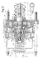
- a brake booster 7 which is a servomechanism designed to multiply the manual pedal force provided by the driver of a vehicle to operate the vehicle brake system via a piston 91 of a master cylinder 90.
- the brake booster 7 is connected between a brake pedal linkage 5 and the piston 91 of the master cylinder 90.
- Pressurized air is the energy transfer medium described below, however, other mediums (for example, hydraulic fluid) may be used with minor modifications.
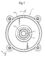
- Figure 1 shows the brake booster 7 in the normal position prior to brake application.
- the brake booster 7 has a housing 50.
- the housing 50 has a first end 51 and a second end 52.
- First end 51 is generally sealed and second end 52 is open to the atmosphere through a vent 53.
- First end 51 also has an inlet 56.
- annular flexible diaphragms 41, 42 which are spaced from one another forming a sealed air storage second chamber 57 or air reservoir.
- the second chamber 57 is in fluid communication with the inlet 56.
- a sealed first chamber 58 Between the first flexible diaphragm 41 and the housing first end 51 is a sealed first chamber 58.
- Sealingly connected with the first 41 and second 42 diaphragms along its exterior is an annular shaped power piston 16.
- the power piston 16 has an inner ring 61, front ring 62, intermediate ring 63 and rearward ring 64.
- the rearward ring 64 mounts first and second diaphragms 41 and 42 respectively.
- Intermediate ring 63 forms a support for second diaphragm 42.
- Front ring 62 is threaded to inner ring 61 and holds intermediate and rearward rings 63 and 64 in place.
- the power piston 16 has a first fluid passage 32 connecting the second chamber 57 with the interior of the power piston.
- First fluid passage 32 is comprised of passage 2 in rearward ring 64 and passage 3 in inner ring 61.
- the power piston 16 is biased in a first direction away from the master cylinder 90 by a spring 46.
- the power piston 16 has a second fluid passage 66 from its interior to an area of the housing second end 52 formed by slots 68 and 69 in front and inner rings 62 and 61 respectively.
- a valve seat insert 67 separating the first 58 and second 57 fluid chambers is threadably connected to the inner ring 61.
- Valve seat insert 67 has a valve seat sealing surface 12 made of a compressible material.
- a control valve 8 has a passage 15 connecting the second 57 and first 58 fluid chambers.
- the inlet valve 11 Slidably mounted within power piston 16 is an inlet valve 11.
- the inlet valve 11 is biased by spring 75.
- the inlet valve 11 has a modulated fluid passage 24 between its interior and exterior.
- the inlet valve 11 also has, at a first larger diameter, a valving surface 10 for contact with the valve seat sealing surface 12 to prevent fluid communication between the first fluid passage 32 and the first chamber 58.
- the inlet valve 11 also has a first exterior sliding surface 71 at the first diameter sealed by an O-ring 29.
- the inlet valve 11 At a second diameter, differing from the first diameter (by being smaller) the inlet valve 11 has a second exterior sealing surface 73 and is sealed by O-ring 26. At the second diameter the inlet valve 11 has an exhaust valve seat 9.
- the control valve 8 is connected with the piston 91 of the master cylinder 90 and the brake pedal linkage 5.
- the control valve 8 is biased by a spring 6 away from power piston 16.
- the control valve 8 is slidably and sealably connected in the first end 51 of the housing 50 and is sealed by a lip (or other type seal) seal 30 at the second diameter.
- control valve 8 has a valving surface 37 for mating with the exhaust valve seat 9 at the second diameter. Movement of the control valve 8 by the brake pedal (via brake pedal linkage 5) causes the valving surface 37 to contact the exhaust valve seat 9 to seal off the interior of the inlet valve 11 from the vent 53.
- Pressurized air from a supply source 47 passes through a check valve 45. The air then passes into the second chamber 57. Connecting passages 2 and 3 form a power piston first fluid passage to admit supply pressurized air to annulus 4. All other areas of the brake booster 7 are at atmospheric pressure.
- the valving surface 37 of the control valve 8 is moved into contact with the exhaust valve seat 9, closing annulus 13 from the atmosphere. Further motion (of control valve 8) moves the valving surface 10 of the inlet valve 11 away from contact with the valve seat sealing surface 12 admitting the supply pressure from second chamber 57 to annulus 13. From annulus 13, supply pressure is admitted to first chamber 58 through passage 15 (formed by a milled slot in control valve 8).
- the imbalance of pressure behind power piston 16 causes a force in the direction of the brake pedal linkage 5 force (towards the master cylinder 90).
- the rolling first and second diaphragms 41 and 42 allow the power piston 16 to move in the direction of the push rod force and to push against a reaction support 18 through a reaction ring 19, through a reaction disc 20, through a master cylinder piston guide 21, and finally against the piston 91 of the conventional hydraulic master cylinder 90, to apply the brakes of the vehicle.
- reaction disc 20 Since the reaction disc 20 is a relatively soft elastomer, the force applied to it tends to displace a portion of its volume through a slidable reaction piston 23 to the end of the control valve 8 and hence through the brake pedal linkage 5 and on to the brake pedal where a force proportional to the area of master cylinder piston guide 21 and the reaction piston 23 and the lever ratio of the pedal is transmitted to the foot of the driver.
- the above-noted mechanism by providing a force directly proportional to that applied to the piston 91, provides the driver with the "feel" necessary to a controlled vehicle stop. Using this feedback mechanism, the driver is able to meter the supply pressure from second chamber 57 to first chamber 58 and is in full control of the modulated pressure in second chamber 58.
- Modulated fluid passage 24 admits modulated air into an annulus 25. Since the diameter at the inside of o-ring 26 is equal to that of the valving surface 37 of the control valve 8, and the pressure on both areas is modulated pressure, it follows that the inlet valve 11 is balanced for any value of modulated pressure. Modulated air in annulus 13 is admitted to first chamber 58 through passage 15. Since the diameter at the inside of lip seal 30 is equal to that of the valving surface 37 of the control valve 8 and the pressure on both areas is modulated pressure, it follows that the control valve 8 is balanced for any value of modulated pressure. The above together with the balancing of the inlet valve 11 (described later) provides for a controlled force between valving surface 37 of the control valve 8 and the face of the exhaust valve seat 9 which is unaffected by modulated pressure.
- the device would tend to self-apply, self-release, or create variable forces for different pressure values dependent on the magnitude and/or direction of the area imbalance.
- the concept of using two opposed rolling diaphragms 41,42 to admit pressurized fluid to the valving area from a stationary housing has the advantage of providing a low friction leak-proof means of transferring pressurized fluid from the stationary housing 50. Also the diaphragms 41,42 in combination with check valve 45 serve as a fluid reservoir for emergency stops when a compressible medium is employed.
- the exterior bolting arrangement provides a of transmitting brake loads from the master cylinder 90 to the support area of the vehicle fire wall 80.
- the above construction eliminates the necessity for heavy booster housing structures to support the brake transmitted loads.
- Four bolts 70 are shown in the present design. However three-bolt or two-bolt configurations are feasible. Other designs utilize bolts for carrying master cylinder loads, however, prior boosters use bolts that pierce the housing walls necessitating expensive seals with additional friction at several points on each bolt.
- the design of the present brake booster 7 uses fully exterior bolts 70 that require no seals of any kind.
- the present invention provides a method of boosting the force exerted by a vehicle occupant on a brake pedal against the piston 91 of a master cylinder 90 the method in combination comprising:
Landscapes
- Engineering & Computer Science (AREA)
- Transportation (AREA)
- Mechanical Engineering (AREA)
- Braking Systems And Boosters (AREA)
Applications Claiming Priority (2)
| Application Number | Priority Date | Filing Date | Title |
|---|---|---|---|
| US239098 | 1981-02-27 | ||
| US07/239,098 US4905571A (en) | 1988-08-31 | 1988-08-31 | Air booster with pressure-balanced valve |
Publications (2)
| Publication Number | Publication Date |
|---|---|
| EP0357220A1 true EP0357220A1 (fr) | 1990-03-07 |
| EP0357220B1 EP0357220B1 (fr) | 1992-10-21 |
Family
ID=22900610
Family Applications (1)
| Application Number | Title | Priority Date | Filing Date |
|---|---|---|---|
| EP89307629A Expired EP0357220B1 (fr) | 1988-08-31 | 1989-07-27 | Servofrein |
Country Status (4)
| Country | Link |
|---|---|
| US (1) | US4905571A (fr) |
| EP (1) | EP0357220B1 (fr) |
| CA (1) | CA1326253C (fr) |
| DE (1) | DE68903256T2 (fr) |
Families Citing this family (11)
| Publication number | Priority date | Publication date | Assignee | Title |
|---|---|---|---|---|
| US5076141A (en) * | 1989-05-12 | 1991-12-31 | Jidosha Kiki Co., Ltd. | Liquid pressure booster |
| US5031404A (en) * | 1989-09-27 | 1991-07-16 | General Motors Corporation | Pressurized air booster |
| US5263399A (en) * | 1992-06-08 | 1993-11-23 | General Motors Corporation | Fluid booster with dual member input valve |
| DE4234041C1 (de) * | 1992-10-09 | 1994-03-17 | Daimler Benz Ag | Bremsdruck-Steuereinrichtung für ein Straßenfahrzeug |
| DE4418584C1 (de) * | 1994-05-27 | 1995-09-21 | Daimler Benz Ag | Bremskraftverstärker |
| DE4427907B4 (de) * | 1994-08-06 | 2008-04-30 | Continental Teves Ag & Co. Ohg | Pneumatischer Bremskraftverstärker für Kraftfahrzeuge |
| US5570622A (en) * | 1995-06-08 | 1996-11-05 | General Motors Corporation | Power booster with guided power piston |
| FR2765174B1 (fr) * | 1997-06-27 | 1999-08-27 | Bosch Sist De Frenado Sl | Servomoteur pneumatique d'assistance au freinage a clapet perfectionne |
| US6006520A (en) * | 1997-10-06 | 1999-12-28 | General Motors Corporation | Pneumatic assisted brake apply system |
| US6006649A (en) * | 1998-09-29 | 1999-12-28 | General Motors Corporation | Dual reaction ratio power booster |
| CN108679117B (zh) * | 2018-06-26 | 2024-12-13 | 国器智眸(重庆)科技有限公司 | 一种制动力控制机构 |
Citations (2)
| Publication number | Priority date | Publication date | Assignee | Title |
|---|---|---|---|---|
| DE1430113B (de) * | Kelsey-Hayes Company, Romulus, Mich. (V.St.A.) | Druckmittelbetätigter Servomotor, insbesondere für Kiraftfahrzeugbremsanlagen | ||
| US2761427A (en) * | 1951-09-20 | 1956-09-04 | Bendix Westinghouse Automotive | Fluid pressure actuator |
Family Cites Families (5)
| Publication number | Priority date | Publication date | Assignee | Title |
|---|---|---|---|---|
| US3013536A (en) * | 1959-01-29 | 1961-12-19 | Bendix Corp | Fluid pressure motor construction |
| US2976850A (en) * | 1959-08-07 | 1961-03-28 | Kelsey Hayes Co | Fluid pressure operated motor |
| US3143926A (en) * | 1960-10-07 | 1964-08-11 | Kelsey Hayes Co | Booster brake mechanism |
| BR8401676A (pt) * | 1983-05-24 | 1985-03-26 | Teves Gmbh Alfred | Dispositivo de reforco de forca de freio a vacuo |
| JPS60157951A (ja) * | 1984-01-28 | 1985-08-19 | Tokico Ltd | 車両ブレ−キ装置 |
-
1988
- 1988-08-31 US US07/239,098 patent/US4905571A/en not_active Expired - Lifetime
-
1989
- 1989-07-27 DE DE8989307629T patent/DE68903256T2/de not_active Expired - Fee Related
- 1989-07-27 EP EP89307629A patent/EP0357220B1/fr not_active Expired
- 1989-08-18 CA CA000608811A patent/CA1326253C/fr not_active Expired - Fee Related
Patent Citations (3)
| Publication number | Priority date | Publication date | Assignee | Title |
|---|---|---|---|---|
| DE1430113B (de) * | Kelsey-Hayes Company, Romulus, Mich. (V.St.A.) | Druckmittelbetätigter Servomotor, insbesondere für Kiraftfahrzeugbremsanlagen | ||
| DE1426459C (de) * | 1972-05-04 | The Bendix Corp., Detroit, Mich. (V.StA.) | Strömungsmitteldruck-Servomotor | |
| US2761427A (en) * | 1951-09-20 | 1956-09-04 | Bendix Westinghouse Automotive | Fluid pressure actuator |
Also Published As
| Publication number | Publication date |
|---|---|
| CA1326253C (fr) | 1994-01-18 |
| EP0357220B1 (fr) | 1992-10-21 |
| US4905571A (en) | 1990-03-06 |
| DE68903256T2 (de) | 1993-03-04 |
| DE68903256D1 (de) | 1992-11-26 |
Similar Documents
| Publication | Publication Date | Title |
|---|---|---|
| EP2762371B1 (fr) | Dispositif de frein électrique | |
| EP0357220B1 (fr) | Servofrein | |
| US3780620A (en) | Pressure differential assist for a servomotor | |
| US3162018A (en) | Split system master cylinder and brake booster | |
| WO1999059854A3 (fr) | Servo-frein a fonction de frein de secours | |
| EP0110740A1 (fr) | Ensemble d'actionnement pour un frein | |
| JP3940960B2 (ja) | ヒステリシスを低減し可変ブースト比を有するブースト式ブレーキ装置 | |
| US4110985A (en) | Dual power brake booster | |
| US4702530A (en) | Hydraulic brake system with fast-fill cylinder | |
| US5031404A (en) | Pressurized air booster | |
| US5263399A (en) | Fluid booster with dual member input valve | |
| JP4207170B2 (ja) | 動的に解除可能な流体反力を備える改良したマスターシリンダ | |
| US4678242A (en) | Hydraulic vehicle brake system with anti-locking | |
| US4232520A (en) | Actuator assemblies for vehicle hydraulic braking systems | |
| US5305606A (en) | Actuating unit for hydraulic brake systems | |
| GB2059526A (en) | Pneumatic ro hydraulic pressure converters for vehicle brake systems | |
| US3109282A (en) | Servomotor construction | |
| JPS5950848A (ja) | 液圧ブレ−キシステム | |
| US4468926A (en) | Vehicle brake booster | |
| US5012647A (en) | Throttle-controlled hydraulic power brake booster | |
| US6606859B1 (en) | Master cylinder | |
| JPS62110556A (ja) | 制動圧ジエネレ−タ | |
| US6195994B1 (en) | Master cylinder with hydraulic reaction operating with developing pressure | |
| EP0613430A1 (fr) | Modificateur d'une force de reaction d'un frein assiste a vide. | |
| US5259666A (en) | Double brake booster |
Legal Events
| Date | Code | Title | Description |
|---|---|---|---|
| PUAI | Public reference made under article 153(3) epc to a published international application that has entered the european phase |
Free format text: ORIGINAL CODE: 0009012 |
|
| AK | Designated contracting states |
Kind code of ref document: A1 Designated state(s): DE FR GB |
|
| 17P | Request for examination filed |
Effective date: 19900501 |
|
| 17Q | First examination report despatched |
Effective date: 19911002 |
|
| GRAA | (expected) grant |
Free format text: ORIGINAL CODE: 0009210 |
|
| AK | Designated contracting states |
Kind code of ref document: B1 Designated state(s): DE FR GB |
|
| REF | Corresponds to: |
Ref document number: 68903256 Country of ref document: DE Date of ref document: 19921126 |
|
| ET | Fr: translation filed | ||
| PLBE | No opposition filed within time limit |
Free format text: ORIGINAL CODE: 0009261 |
|
| STAA | Information on the status of an ep patent application or granted ep patent |
Free format text: STATUS: NO OPPOSITION FILED WITHIN TIME LIMIT |
|
| 26N | No opposition filed | ||
| PGFP | Annual fee paid to national office [announced via postgrant information from national office to epo] |
Ref country code: GB Payment date: 20010618 Year of fee payment: 13 |
|
| PGFP | Annual fee paid to national office [announced via postgrant information from national office to epo] |
Ref country code: FR Payment date: 20010719 Year of fee payment: 13 |
|
| REG | Reference to a national code |
Ref country code: GB Ref legal event code: IF02 |
|
| PG25 | Lapsed in a contracting state [announced via postgrant information from national office to epo] |
Ref country code: GB Free format text: LAPSE BECAUSE OF NON-PAYMENT OF DUE FEES Effective date: 20020727 |
|
| GBPC | Gb: european patent ceased through non-payment of renewal fee |
Effective date: 20020727 |
|
| PG25 | Lapsed in a contracting state [announced via postgrant information from national office to epo] |
Ref country code: FR Free format text: LAPSE BECAUSE OF NON-PAYMENT OF DUE FEES Effective date: 20030331 |
|
| REG | Reference to a national code |
Ref country code: FR Ref legal event code: ST |
|
| PGFP | Annual fee paid to national office [announced via postgrant information from national office to epo] |
Ref country code: DE Payment date: 20050721 Year of fee payment: 17 |
|
| PG25 | Lapsed in a contracting state [announced via postgrant information from national office to epo] |
Ref country code: DE Free format text: LAPSE BECAUSE OF NON-PAYMENT OF DUE FEES Effective date: 20070201 |