EP0357286A2 - Methode und System zum Versorgen eines Reibelementes mit Hydraulikflüssigkeit in einem automatischen Getriebe - Google Patents
Methode und System zum Versorgen eines Reibelementes mit Hydraulikflüssigkeit in einem automatischen Getriebe Download PDFInfo
- Publication number
- EP0357286A2 EP0357286A2 EP89308289A EP89308289A EP0357286A2 EP 0357286 A2 EP0357286 A2 EP 0357286A2 EP 89308289 A EP89308289 A EP 89308289A EP 89308289 A EP89308289 A EP 89308289A EP 0357286 A2 EP0357286 A2 EP 0357286A2
- Authority
- EP
- European Patent Office
- Prior art keywords
- pressure
- regulated output
- source
- fluid
- output pressure
- Prior art date
- Legal status (The legal status is an assumption and is not a legal conclusion. Google has not performed a legal analysis and makes no representation as to the accuracy of the status listed.)
- Granted
Links
Images

Classifications
-
- F—MECHANICAL ENGINEERING; LIGHTING; HEATING; WEAPONS; BLASTING
- F16—ENGINEERING ELEMENTS AND UNITS; GENERAL MEASURES FOR PRODUCING AND MAINTAINING EFFECTIVE FUNCTIONING OF MACHINES OR INSTALLATIONS; THERMAL INSULATION IN GENERAL
- F16H—GEARING
- F16H61/00—Control functions within control units of change-speed- or reversing-gearings for conveying rotary motion ; Control of exclusively fluid gearing, friction gearing, gearings with endless flexible members or other particular types of gearing
- F16H61/04—Smoothing ratio shift
- F16H61/06—Smoothing ratio shift by controlling rate of change of fluid pressure
- F16H61/065—Smoothing ratio shift by controlling rate of change of fluid pressure using fluid control means
-
- F—MECHANICAL ENGINEERING; LIGHTING; HEATING; WEAPONS; BLASTING
- F16—ENGINEERING ELEMENTS AND UNITS; GENERAL MEASURES FOR PRODUCING AND MAINTAINING EFFECTIVE FUNCTIONING OF MACHINES OR INSTALLATIONS; THERMAL INSULATION IN GENERAL
- F16H—GEARING
- F16H59/00—Control inputs to control units of change-speed- or reversing-gearings for conveying rotary motion
- F16H59/68—Inputs being a function of gearing status
- F16H59/72—Inputs being a function of gearing status dependent on oil characteristics, e.g. temperature, viscosity
-
- F—MECHANICAL ENGINEERING; LIGHTING; HEATING; WEAPONS; BLASTING
- F16—ENGINEERING ELEMENTS AND UNITS; GENERAL MEASURES FOR PRODUCING AND MAINTAINING EFFECTIVE FUNCTIONING OF MACHINES OR INSTALLATIONS; THERMAL INSULATION IN GENERAL
- F16H—GEARING
- F16H61/00—Control functions within control units of change-speed- or reversing-gearings for conveying rotary motion ; Control of exclusively fluid gearing, friction gearing, gearings with endless flexible members or other particular types of gearing
- F16H61/04—Smoothing ratio shift
- F16H61/06—Smoothing ratio shift by controlling rate of change of fluid pressure
- F16H61/065—Smoothing ratio shift by controlling rate of change of fluid pressure using fluid control means
- F16H61/067—Smoothing ratio shift by controlling rate of change of fluid pressure using fluid control means using an accumulator
Definitions
- This invention relates to a method and system for supplying hydraulic fluid to a friction element of an automatic transmission.
- the period during which a gearshift is made by an automatic transmission from any forward gear to reverse, or from reverse to a forward gear must extend no longer than five to ten seconds under any condition and should be shorter than that at ambient temperature above 0 o F.
- Such transmissions prevent sudden, harsh gear engagements by controlling the time rate at which pressure rises in a clutch or brake required to complete the gearshift.
- the clutch or brake must engage rapidly to meet operator expectations.
- temperature is low and viscosity of transmission fluid is high, engagements are inherently sluggish because of delay in filling the clutch cylinder due to flow resistance.
- the hydraulic control circuit supplies fluid to the clutch through multiple control valves arranged in parallel and through a shuttle valve where fluid from both control valves combines to produce a single fluid source connected to the cylinder of the clutch.
- One pressure source supplies the control valve of an accumulator used during forward upshifts and low-power reverse engagement at normal ambient temperature.
- the clutch is supplied exclusively from the output of the control valve associated with the accumulator.
- a throttle valve produces high pressure output, which causes a second source of hydraulic pressure, not associated with accumulator operation, to be connected to the shuttle valve and clutch.
- throttle valve pressure is low, the clutch is supplied from the hydraulic circuit that includes the accumulator and its associated control valve. But, when throttle valve pressure is high, the control senses need for rapid engagement of the clutch and connects an auxiliary fluid pressure source to the shuttle valve to avoid delay in engagement.
- the accumulator control valve regulates supply pressure by balancing a control feedback pressure force against a spring force, vents regulated output pressure when feedback pressure is high, and closes the opening to vent when feedback pressure is again low.
- a control feedback pressure force against a spring force
- vents regulated output pressure when feedback pressure is high
- closes the opening to vent when feedback pressure is again low.
- viscosity of hydraulic fluid within the shuttle valve is high. This delays, and may prevent entirely, closure of a shuttle valve port connected to the accumulator control valve. This port remains open while the control valve is regulating.
- the clutch cylinder and shuttle valve are successively opened and closed to vent while the accumulator control valve regulates output pressure.
- a system for supplying hydraulic fluid to a friction element of an automatic transmission comprising, a source of fluid pressure, valve means including feedback control pressure connected to regulated output pressure, a spool having a control pressure surface connected to feedback control pressure and urged by feedback control pressure to close communication between the pressure source and regulated output pressure , and means urging the spool the effect of feedback control pressure to open communication between the pressure source and regulated output pressure, for throttling output of the pressure source and producing regulated output pressure in accordance with the magnitude of regulated output pressure without venting either feedback control pressure or regulated output pressure, and shuttle valve means for opening communication between two members of a group comprising regulated output pressure , the pressure source and the friction element and closing communication between mutually communicating members of said group and the other member of said group.
- a system for supplying hydraulic fluid to a friction element of an automatic transmission comprising, a source of fluid pressure, a vent port, valve means for regulating output of the second pressure source and producing regulated output pressure, including feedback control pressure connected to regulated output pressure, a spool having a control pressure surface connected to feedback control pressure and biased by feedback control pressure to a first position where the pressure source is closed to regulated output pressure, a spring biasing the spool to a second position where the pressure source is open to regulated output pressure, shuttle valve means for opening communication between two members of a group comprising regulated output pressure, the pressure source and the friction element, and closing communication between mutually communicating members of said group and the other member of said group, and means for preventing communication between the vent port and regulated output pressure regardless of the state of the shuttle valve means.
- a method for pressurising a friction element of an automatic transmission through a shuttle valve supplied with pressurised fluid from a source of fluid pressure comprising, regulating output of the pressure source by balancing regulated output pressure against a spring force without venting the pressure source or the regulated output pressure, opening communication between two members of a group comprising regulated output pressure, the pressure source and the friction element, closing communication between mutually communicating members of said group and the other member of said group, preventing fluid flow from the shuttle valve to the regulator valve regardless of the state of the shuttle valve.
- a method for pressurising a friction element of an automatic transmission through a shuttle valve supplied with pressurised fluid from a source of fluid pressure comprising, regulating output of the pressure source by balancing regulated output pressure against a spring force without venting the pressure source or the regulated output pressure, opening communication between two members of a group comprising regulated output pressure, the pressure source and the friction element, closing communication between mutually communicating members of said group and the other member of said group, and defining a first volume located at one side of a piston movable within a cylinder, defining a second volume located at the opposite side of the piston and communicating with regulated output pressure, urging the piston to minimise the first volume, regulating the flow rate of fluid between said regulator valve and said second volume, and preventing fluid flow from the shuttle valve to the regulator valve regardless of the state of the shuttle valve.
- the accumulator control valve performs its normal function of regulating output pressure and controlling the time rate of increase of clutch pressure by expanding a first volume of the accumulator at a rate controlled by the magnitude of control pressure within a second volume of the accumulator, the force of a compression spring biasing an accumulator plunger against this expansion of the first volume, and the flow rate through an orifice of predetermined diameter.
- the clutch is hydraulically actuated when passage 286 is pressurised and disengaged when the passage is vented.
- the clutch is engaged when the transmission operates in third gear, whether the gear be selected manually by the vehicle operator or automatically through operation of a transmission control circuit, fourth gear and reverse gear.
- a gear ratio change and engaging the clutch which is a friction element actuated by a pressurised hydraulic fluid
- a piston movable within a hydraulic cylinder, moves friction discs into driving engagement after closing clearance spaces between the friction discs, a load block, and clutch piston.
- pressure within the clutch cylinder remains relatively low because volume of the clutch cylinder is expanding as clearances are removed.
- the friction element is pressurised through operation of various control valves which connect regulated line pressure to the clutch in accordance with requirements of several control valves. During a shift to reverse drive and while throttle valve pressure is high, a period exists during which several control valves direct pressure to the friction element concurrently.
- These multiple sources of pressurised hydraulic fluid are directed to the clutch through a single hydraulic passage connected to the outlet of a ball shuttle valve.
- passage 168 carries regulated line pressure to an input port of a manual valve 160 controlled by the vehicle operator and moved manually between selected gears and drive ranges the transmission is able to produce.
- Valve 160 connects regulated line pressure to passages 290 and 310 when reverse drive is selected.
- a control valve such as 2-3 shift valve 232, connects passages 290 and 280 when the operator manually selects reverse gear.
- Passage 280 which contains a 0.15 inch diameter orifice 12, connects shift valve 232 to control valve 282 located above accumulator 262.
- the accumulator includes a hydraulic cylinder 14, a plunger 16 movable along the axis of the cylinder, and compression springs 18 urging the plunger to top of the cylinder.
- the plunger defines within the cylinder a first volume 22, whose volume decreases as the plunger moves downward, and a second volume 20, whose size expands as the plunger moves downward. Volume 22 is filled with hydraulic fluid at a first control pressure TVLM supplied through passage 272, which acts with springs 18 to force the plunger to top of the cylinder.
- Control valve 282 includes a spool 24 movable parallel to the axis of the accumulator, a compression spring 27 urging spool 24 upward, a valve land 26 formed on the spool having a feedback control pressure surface 28, and a vent port 30 through which the valve is connected to a low pressure sump.
- the control valve includes several additional ports: an inlet port 32 by which passage 280 is admitted to the valve; a regulated output pressure port 34 through which regulated output pressure exits the valve, and a feedback control port 36 connected by passage 38 to the regulated output pressure passage 40, which carries regulated output pressure to shuttle valve 241.
- the second volume 20 is connected by passage 42 through an orifice 284 of predetermined diameter to regulated output pressure passage 40.
- the length of land 26 maintains vent port 30 closed at all times regardless of position of spool 24.
- Shuttle valve 241 includes regulated pressure input port 44 and port 46, through which the first pressure source, passage 344, enters the shuttle valve.
- Orifice 14 in passage 344 has a diameter of approximately10.040 inches.
- Port 48 through which passage 286 communicates the cylinder of clutch 98 to the interior of the shuttle valve, remains open at all times.
- Shuttle ball 50 which is moved within the valve by flow of hydraulic fluid through the valve, becomes seated on ports 44, 46 and remains seated due to internal pressure within the valve. For example, when port 44 is sealed by ball 50, passages 286 and 344 communicate. When the ball is seated on port 46, passages 286 and 40 communicate. Normally, the ball moves to a seated or sealing position on the port in which lower hydraulic pressure is present.
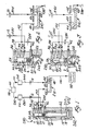
- Figure 1 shows the system at the start of clutch actuation when fluid from both circuits supplies shuttle 241 and clutch 98.
- Control valve 282 regulates pressure at output port 34 by balancing a pressure force on surface 28 against the spring force on the opposite end of spool 24.
- pressure in passage 280 and inlet port 32 is low, the valve is in the position shown in Figure 1, inlet 32 and output 34 are open, and second volume 20 is filled through passage 42 and orifice 284.
- pressure fluid source 280 increases, feedback pressure force on surface 28 increases in relation to the force of spring 27, and valve 282 regulates by throttling pressure in passage 280.
- valve 282 moves upward and downward within the bore of the valve to the position shown in Figure 2, where the valve completely closes inlet port 32 and outlet port 34, momentarily disconnecting flow from valve 282 to valve 241 and causing feedback control pressure momentarily to decrease because of expansion of volume 20, while maintaining vent port 30 closed.
- Valve 282 continues regulation by moving upward due to the effect of the spring and reduced feedback control pressure, thereby opening passage 280 to passage 40 until control feedback pressure produces on pressure surface 28 a force exceeding the spring force, due to increased regulated output pressure.
- fluid entering shuttle valve 241 from passages 40 and 344 through ports 44 and 46 flows to clutch 98.
- volume 20 of accumulator 262 expands against hydraulic pressure within volume 22 and the effect of compression springs 18 at a rate consistent with the pressure drop across orifice 284.
- Figure 3 shows plunger 16 moved to a lower position while filling volume 20 and forcing fluid from the bottom of the accumulator cylinder. At normal operating fluid temperature, the plunger bottoms in about 1.5 seconds.
- FIG. 4 shows, while the cylinder of clutch 98 is filling with fluid through passage 286 from the pocket of shuttle valve 241, both ports of the valve 241 are unsealed by shuttle ball 50 and control valve 282 is forced by spring 27 to the upper end of its bore, thereby opening passage 280 to passage 40.
- Valve 282 includes spool 25 having a shorter land 64 than land 26. As output pressure increases, pressure force resulting from feedback control pressure on surface 28 forces spool 25 downward against compression spring 27 until feedback control pressure is open to exhaust vent 30.
Landscapes
- Engineering & Computer Science (AREA)
- General Engineering & Computer Science (AREA)
- Physics & Mathematics (AREA)
- Fluid Mechanics (AREA)
- Mechanical Engineering (AREA)
- Control Of Transmission Device (AREA)
- Hydraulic Clutches, Magnetic Clutches, Fluid Clutches, And Fluid Joints (AREA)
Applications Claiming Priority (2)
| Application Number | Priority Date | Filing Date | Title |
|---|---|---|---|
| US07/239,379 US4930376A (en) | 1988-09-01 | 1988-09-01 | Minimizing delay in low temperature engagement of automatic transmission clutch or brake |
| US239379 | 1988-09-01 |
Publications (3)
| Publication Number | Publication Date |
|---|---|
| EP0357286A2 true EP0357286A2 (de) | 1990-03-07 |
| EP0357286A3 EP0357286A3 (de) | 1991-07-24 |
| EP0357286B1 EP0357286B1 (de) | 1994-12-14 |
Family
ID=22901911
Family Applications (1)
| Application Number | Title | Priority Date | Filing Date |
|---|---|---|---|
| EP89308289A Expired - Lifetime EP0357286B1 (de) | 1988-09-01 | 1989-08-15 | Methode und System zum Versorgen eines Reibelementes mit Hydraulikflüssigkeit in einem automatischen Getriebe |
Country Status (3)
| Country | Link |
|---|---|
| US (1) | US4930376A (de) |
| EP (1) | EP0357286B1 (de) |
| DE (1) | DE68919944T2 (de) |
Families Citing this family (3)
| Publication number | Priority date | Publication date | Assignee | Title |
|---|---|---|---|---|
| JP2830173B2 (ja) * | 1989-09-30 | 1998-12-02 | アイシン精機株式会社 | 自動変速機の変速制御装置 |
| DE69108335T2 (de) * | 1990-08-28 | 1995-08-31 | Mazda Motor | Gangwechseleinrichtung eines automatischen Getriebes. |
| US5601172A (en) * | 1994-08-01 | 1997-02-11 | Case Corporation | Power take off clutch engagement control system for cold weather starting |
Family Cites Families (19)
| Publication number | Priority date | Publication date | Assignee | Title |
|---|---|---|---|---|
| US3340895A (en) * | 1965-08-27 | 1967-09-12 | Sanders Associates Inc | Modular pressure regulating and transfer valve |
| US3393585A (en) * | 1966-01-05 | 1968-07-23 | Ford Motor Co | Control system for a multiple speed ratio power transmission mechanism and semiautomatic and automatic ratio changing features |
| US3583422A (en) * | 1967-10-19 | 1971-06-08 | Zahnradfabrik Friedrichshafen | Valve construction for controlled pressure buildup in fluid-operated brake or clutch |
| YU33129B (en) * | 1968-07-29 | 1976-04-30 | Zahnradfabrik Friedrichshafen | Hidraulicni uredaj za ukljucivanje stepena prenosa |
| US3541885A (en) * | 1969-01-16 | 1970-11-24 | Ford Motor Co | Power shift transmission for racing vehicles |
| US3613484A (en) * | 1969-12-08 | 1971-10-19 | Ford Motor Co | Ratio shift timing valves for use in a control system for a multiple ratio automatic power transmission mechanism |
| US3714836A (en) * | 1971-02-16 | 1973-02-06 | Ford Motor Co | Automatic transmission controls for an automotive vehicle driveline |
| US3706240A (en) * | 1971-06-17 | 1972-12-19 | Ford Motor Co | Four-speed ratio automatic power transmission mechanism |
| US3820417A (en) * | 1972-08-10 | 1974-06-28 | Caterpillar Tractor Co | Controls for sequentially engaging transmission torque convertor lockup and master clutches |
| JPS5146223B2 (de) * | 1972-10-28 | 1976-12-08 | ||
| US4005620A (en) * | 1975-04-23 | 1977-02-01 | Zahnradfabrik Friedrichshafen Ag | Hydraulic gear-shift control for automotive transmission systems |
| DE2658195C2 (de) * | 1976-12-22 | 1978-12-14 | Zahnradfabrik Friedrichshafen Ag, 7990 Friedrichshafen | Druckmittelkreislauf für ein hydrodynamisch-mechanisches Verbundgetriebe |
| JPS5945864B2 (ja) * | 1977-04-28 | 1984-11-09 | トヨタ自動車株式会社 | 油圧制御装置を有する自動変速機 |
| US4265346A (en) * | 1979-01-04 | 1981-05-05 | Ford Motor Company | Control valve mechanism for hydraulic clutch in a power transmission mechanism |
| JPS5655749A (en) * | 1979-10-15 | 1981-05-16 | Nissan Motor Co Ltd | Speed changing shock reducing device for automatic change gear |
| US4418587A (en) * | 1980-10-27 | 1983-12-06 | General Motors Corporation | Hydraulic system pressure control for a power transmission |
| JPS57137751A (en) * | 1981-02-17 | 1982-08-25 | Nissan Motor Co Ltd | Manual valve for automatic change gear |
| US4637281A (en) * | 1985-07-19 | 1987-01-20 | Ford Motor Company | Control valve system for a four-speed automatic power transmission transaxle |
| US4756213A (en) * | 1987-06-01 | 1988-07-12 | Saturn Corporation | Transmission control with a clutch priority valve |
-
1988
- 1988-09-01 US US07/239,379 patent/US4930376A/en not_active Expired - Fee Related
-
1989
- 1989-08-15 EP EP89308289A patent/EP0357286B1/de not_active Expired - Lifetime
- 1989-08-15 DE DE68919944T patent/DE68919944T2/de not_active Expired - Lifetime
Also Published As
| Publication number | Publication date |
|---|---|
| DE68919944D1 (de) | 1995-01-26 |
| DE68919944T2 (de) | 1995-05-04 |
| EP0357286A3 (de) | 1991-07-24 |
| EP0357286B1 (de) | 1994-12-14 |
| US4930376A (en) | 1990-06-05 |
Similar Documents
| Publication | Publication Date | Title |
|---|---|---|
| US4349088A (en) | Device for controlling a lock-up clutch in an automatic transmission with a lock-up clutch equipped fluid torque converter | |
| US4527448A (en) | Hydraulic control system for electronic transmission control | |
| US7104380B2 (en) | Dual area piston for transmission clutch and sequential control therefor | |
| US4023444A (en) | Pressure control circuit for use in automatic transmission of vehicle | |
| US4106369A (en) | Oil pressure control system for an automatic transmission system | |
| US4541308A (en) | Hydraulic control system for electronic transmission control | |
| US4050332A (en) | Oil pressure control system for an automatic transmission system | |
| JP3032093B2 (ja) | 自動変速機の油圧制御装置の変速バルブ | |
| US4709596A (en) | Control of a vehicle automatic transmission | |
| US3895547A (en) | Transmission control system | |
| US4628771A (en) | Hydraulic clutch pressure control for an electronically controlled transmission | |
| JPS5829418B2 (ja) | 一対のレシオ確立装置用制御装置 | |
| JPH05248526A (ja) | 自動変速機のクラッチ制御方法及び装置 | |
| EP0357286B1 (de) | Methode und System zum Versorgen eines Reibelementes mit Hydraulikflüssigkeit in einem automatischen Getriebe | |
| JP2655260B2 (ja) | 車両用油圧作動式変速機の制御装置 | |
| US4041810A (en) | Transmission shift control device system | |
| KR960016792B1 (ko) | 자동 압력 제어용 모듈레이팅 인칭 밸브 | |
| US4966050A (en) | Control valve for reducing harshness of engagement of an automatic transmission clutch | |
| US4065985A (en) | Oil pressure control system for an automatic transmission system | |
| US6453763B2 (en) | Control apparatus for hydraulically-operated vehicular transmission | |
| JPS5846248A (ja) | 電子制御式油圧制御装置 | |
| JP2000205407A (ja) | 自動変速機の液圧制御装置 | |
| US5117712A (en) | Shift control device for an automatic transmission | |
| US5429560A (en) | Valve and hydraulic system for operating a friction element of an automatic transmission | |
| JPS6030864A (ja) | 直結クラツチ附流体継手の流体制御回路 |
Legal Events
| Date | Code | Title | Description |
|---|---|---|---|
| PUAI | Public reference made under article 153(3) epc to a published international application that has entered the european phase |
Free format text: ORIGINAL CODE: 0009012 |
|
| AK | Designated contracting states |
Kind code of ref document: A2 Designated state(s): DE FR GB |
|
| PUAL | Search report despatched |
Free format text: ORIGINAL CODE: 0009013 |
|
| AK | Designated contracting states |
Kind code of ref document: A3 Designated state(s): DE FR GB |
|
| 17P | Request for examination filed |
Effective date: 19911218 |
|
| 17Q | First examination report despatched |
Effective date: 19930421 |
|
| GRAA | (expected) grant |
Free format text: ORIGINAL CODE: 0009210 |
|
| AK | Designated contracting states |
Kind code of ref document: B1 Designated state(s): DE FR GB |
|
| PG25 | Lapsed in a contracting state [announced via postgrant information from national office to epo] |
Ref country code: FR Effective date: 19941214 |
|
| REF | Corresponds to: |
Ref document number: 68919944 Country of ref document: DE Date of ref document: 19950126 |
|
| EN | Fr: translation not filed | ||
| PLBE | No opposition filed within time limit |
Free format text: ORIGINAL CODE: 0009261 |
|
| STAA | Information on the status of an ep patent application or granted ep patent |
Free format text: STATUS: NO OPPOSITION FILED WITHIN TIME LIMIT |
|
| 26N | No opposition filed | ||
| PGFP | Annual fee paid to national office [announced via postgrant information from national office to epo] |
Ref country code: GB Payment date: 19970808 Year of fee payment: 9 |
|
| PGFP | Annual fee paid to national office [announced via postgrant information from national office to epo] |
Ref country code: DE Payment date: 19970904 Year of fee payment: 9 |
|
| PG25 | Lapsed in a contracting state [announced via postgrant information from national office to epo] |
Ref country code: GB Free format text: LAPSE BECAUSE OF NON-PAYMENT OF DUE FEES Effective date: 19980815 |
|
| PG25 | Lapsed in a contracting state [announced via postgrant information from national office to epo] |
Ref country code: DE Free format text: LAPSE BECAUSE OF THE APPLICANT RENOUNCES Effective date: 19980826 |
|
| GBPC | Gb: european patent ceased through non-payment of renewal fee |
Effective date: 19980815 |