EP0357352B1 - Videosignalaufzeichnungs-/-wiedergabegerät - Google Patents
Videosignalaufzeichnungs-/-wiedergabegerät Download PDFInfo
- Publication number
- EP0357352B1 EP0357352B1 EP19890308650 EP89308650A EP0357352B1 EP 0357352 B1 EP0357352 B1 EP 0357352B1 EP 19890308650 EP19890308650 EP 19890308650 EP 89308650 A EP89308650 A EP 89308650A EP 0357352 B1 EP0357352 B1 EP 0357352B1
- Authority
- EP
- European Patent Office
- Prior art keywords
- signals
- recording
- synchronous
- reproducing
- signal
- Prior art date
- Legal status (The legal status is an assumption and is not a legal conclusion. Google has not performed a legal analysis and makes no representation as to the accuracy of the status listed.)
- Expired - Lifetime
Links
- 230000001360 synchronised effect Effects 0.000 claims description 65
- 238000000926 separation method Methods 0.000 claims description 7
- 230000004044 response Effects 0.000 claims description 2
- 230000001934 delay Effects 0.000 claims 2
- 238000010586 diagram Methods 0.000 description 11
- 238000000034 method Methods 0.000 description 4
- 230000005236 sound signal Effects 0.000 description 4
- 239000004065 semiconductor Substances 0.000 description 3
- 230000006870 function Effects 0.000 description 2
- 230000003321 amplification Effects 0.000 description 1
- 238000010276 construction Methods 0.000 description 1
- 230000006866 deterioration Effects 0.000 description 1
- 238000005516 engineering process Methods 0.000 description 1
- 238000012544 monitoring process Methods 0.000 description 1
- 238000003199 nucleic acid amplification method Methods 0.000 description 1
Images


Classifications
-
- G—PHYSICS
- G11—INFORMATION STORAGE
- G11B—INFORMATION STORAGE BASED ON RELATIVE MOVEMENT BETWEEN RECORD CARRIER AND TRANSDUCER
- G11B27/00—Editing; Indexing; Addressing; Timing or synchronising; Monitoring; Measuring tape travel
- G11B27/02—Editing, e.g. varying the order of information signals recorded on, or reproduced from, record carriers
- G11B27/022—Electronic editing of analogue information signals, e.g. audio or video signals
- G11B27/024—Electronic editing of analogue information signals, e.g. audio or video signals on tapes
-
- G—PHYSICS
- G11—INFORMATION STORAGE
- G11B—INFORMATION STORAGE BASED ON RELATIVE MOVEMENT BETWEEN RECORD CARRIER AND TRANSDUCER
- G11B15/00—Driving, starting or stopping record carriers of filamentary or web form; Driving both such record carriers and heads; Guiding such record carriers or containers therefor; Control thereof; Control of operating function
- G11B15/18—Driving; Starting; Stopping; Arrangements for control or regulation thereof
- G11B15/1808—Driving of both record carrier and head
- G11B15/1875—Driving of both record carrier and head adaptations for special effects or editing
-
- G—PHYSICS
- G11—INFORMATION STORAGE
- G11B—INFORMATION STORAGE BASED ON RELATIVE MOVEMENT BETWEEN RECORD CARRIER AND TRANSDUCER
- G11B15/00—Driving, starting or stopping record carriers of filamentary or web form; Driving both such record carriers and heads; Guiding such record carriers or containers therefor; Control thereof; Control of operating function
- G11B15/18—Driving; Starting; Stopping; Arrangements for control or regulation thereof
- G11B15/46—Controlling, regulating, or indicating speed
- G11B15/467—Controlling, regulating, or indicating speed in arrangements for recording or reproducing wherein both record carriers and heads are driven
- G11B15/473—Controlling, regulating, or indicating speed in arrangements for recording or reproducing wherein both record carriers and heads are driven by controlling the speed of the heads
- G11B15/4731—Controlling, regulating, or indicating speed in arrangements for recording or reproducing wherein both record carriers and heads are driven by controlling the speed of the heads control of headwheel rotation
Definitions
- the present invention relates to a video signal recording/reproducing apparatus, and more particularly to such apparatus having an electronic editing function.
- VTR rotary head type video recorder
- the editing operation in a video tape recorder has been called "Electronic Edit”. This electronic editing operation is carried out in principle by erasing portions of video and audio signals, which have already been recorded on a magnetic tape, and then recording new video and audio signals on the erased region of the magnetic tape.
- phase discontinuity of the video signals causes disturbance of synchronisation and deterioration in the quality of the video image.
- a method to servo-control the rotation phases of the rotary drums may be used so that the phase of a vertical synchronous signal of video signals reproduced by a recording head during the reproducing period before the editing start point substantially coincides with the phase of a vertical synchronous signal of the input video signals to be recorded during editing.
- the timing of the video signals reproduced by the recording heads indicates the rotating phase of the recording heads. If the rotation phase of the rotary drum is servo-controlled so that phases of the vertical synchronous signals from video signals reproduced by the recording heads during the reproduction period before the editing start point becomes almost the same as that of the vertical synchronous signals separated from input video signals, the phases of signals recorded on a magnetic tape before the editing start point and those of signals newly recorded after the editing start point become substantially the same. Therefore, it becomes possible to minimise the disturbance during reproduction of video images before and after the editing start point.
- the method described above is effective on a VTR that is reproducing signals using the recording heads.
- this method is not applicable to those VTRs that do not reproduce signals with the recording heads, that is, a type of VTR which has at least one recording head for recording only and at least one head for reproducing. This is because the timing of video signals reproducing by the reproducing head does not represent rotation phases of the recording head as the recording head and the reproducing head are mounted at staggered positons in the rotation direction of the rotary drum (that is, the recording head and the reproducing head are mounted at different mounting angles on the rotary drum).
- Patent Abstracts of Japan, Vol. 9, no 141, (P-364), 15.06.85 (JP.A-60020348), on which document the preamble of claim 1 is based discloses a VTR with a reproduction head placed behind the recording head on a different height so that a previous track is scanned simultaneously with the recording by the recording head. This allows monitoring as well as phase control of the drum with the phase difference between the synchronisation signals separated from the input and the reproduced signals.
- a video signal recording/reproducing apparatus comprises a rotary drum having at least one recording head thereon for recording input video signals on a video tape and at least one reproducing head thereon for reproducing recorded video signals; first and second synchronous separation means for obtaining synchronous signals from the input and reproduced video signals, respectively; means for detecting the phase difference between the synchronous signals obtained by the first and second synchronous signal separation means; and phase control means which employs the detected phase difference between said synchronous signals to synchronise the synchronous signal of the input signal with the synchronous signal of the recorded signal; characterised by said reproducing head being staggered from the recording head in the direction of rotation of the drum; and by memory means for storing a difference signal representing the angle of stagger between the recording and reproducing heads on the drum, said phase control means also employing the stored difference signal thereby compensating for the phase difference caused by the angle of stagger of the recording and reproducing heads.
- phase continuity of video signals before and after the editing start point on a magnetic tape is obtained at the time of editing in the following manner.
- the relationship between the phases of input video signals and the rotation of the rotary drum is controlled on the basis of synchronous signals separated from video signals reproduced by the reproducing head during the reproduction period before the editing start point and synchronous signals separated from input video signals to be recorded.
- a time difference between when the recording heads and the reproducing heads contact the same position on the magnetic tape is measured and stored. That time difference is attributable to the difference in mounting angles of the recording heads and the reproducing heads, which are inherent in the VTR apparatus.
- This time difference is used to control operation of the phase control means and phases of synchronous signals separated from input video signals are shynchronized with phases of synchronous signals separated from reproduced video signals using the time difference.
- the relationship between the phase of input video signals and the rotation of the rotary drum is optimized. Even on a video signal recording/reproducing apparatus that does not reproduce signals using the recording heads, phase continuity of video signals before and after the editing start point on a magnetic tape is obtainable similar to a VTR which reproduces signals from a magnetic tape by use of the recording heads.
- time difference data In order to store the above-mentioned time difference data in a memory means, when the VTR is in the recording state, video signals are reproduced by the reproducing heads immediately after the signals are recorded on a tape by the recording heads.
- a switching means provided at the input side of the demodulation means selects signals reproduced by the reproducing heads and modulated input video signals and supplies the selected signals to the demodulation means. With this switching operation, signals demodulated from modulated input video signals and video signals demodulated from reproduced signals appear alternately as output signals from the demodulation means. Then, synchronous signals are separated from both these output signals of the demodulation means and supplied to the time difference measuring means. Thus, a time difference between synchronous signals of input video signals and synchronous signals of reproduced video signals is measured and the result is stored.
- FIGURE 1 is a block diagram showing the construction of the invention relative to editing of video signals, which is an essential part of a video signal recording/reproducing apparatus related to the first embodiment of this invention.
- the apparatus of this invention is a helical scanning type VTR so designed that a magnetic tape, the recording medium, is wound round a rotary drum over a range of angle somewhat wider than 180°.
- FM modulated video signals are recorded on this magnetic tape by a pair of recording heads provided at positions opposing each other by 180° on the rotary drum, and signals recorded on a magnetic tape are reproduced by a pair of reproducing heads mounted at positions staggered in the rotating direction from the recording heads on the rotary drum.
- input video signals that were input into the video input terminal 1 are FM modulated in the FM modulation circuit 2. Then, these FM video signals are recorded on the magnetic tape 5 by recording current supplied to the recording heads 4a and 4b through a rotary transformer (not illustrated) from the recording amplifiers 3a and 3b.
- the signals reproduced from the magnetic tape 5 by the reproducing heads 6a and 6b are led to the pre-amplifiers 7a and 7b through the rotary transformer (not illustrated) and after amplification are input into a heads switching circuit 8.
- the heads switching circuit 8 outputs a series of continuous signals by switching output signals from the pre-amplifiers 7a and 7b at very 180°.
- the output signal from the heads switching circuit 8, after compensation of its frequency characteristic by the equalizer 10, is fed to the FM demodulation circuit 11, where it is demodulated into a video signal, and output from the video output terminal 12.
- the synchronous separator 13, the first synchronous separation means separates synchronous signals from the input video signals that are input into the video input terminal 1 and sends then to the editing phase control circuit 15.
- the synchronous separator 14, the second synchronous separation means separates synchronous signals from the reproduced video signal that is demodulated in the modulation circuit 11 and sends it to the editing phase control circuit 15.
- a memory 16 stores in advance data on the time difference (identified as ⁇ T) between when the recording heads 4a (4b) and the reproducing heads 6a (6b) each contact the same position on the magnetic tape 5 at a steady rotational speed of the rotary drum 9.
- This time difference ⁇ T depends on the mounting angle difference ⁇ between the recording heads 4a and the reproducing heads 6a or the recording heads 4b and the reproducing heads 6b to the rotary drum 9 as shown in FIGURE 2.
- the time difference data ⁇ T stored in the memory 16 is given to the editing phase control circuit 15 at the time of the editing as data for correction.
- ROM Read Only Memory
- battery backed up RAM Random Access Memory
- DIP switch can be used for the memory 16.
- FIGURE 3 is a diagram for explaining the editing operation called "assemble editing" that is most often used, and shows the relation between the operation mode of the VTR and areas on a magnetic tape in the respective operation mode of the VTR.
- Assemble editing is an editing method to record video signals and audio signals connected to the input terminal of a VTR successively on the magnetic tape by superposing a portion to be newly recorded on a previously recorded portion.
- the VTR stops the recording and running of the magnetic tape. Then, the point E is selected as the next editing start point and the assemble editing is carried out by repeating the above described similar operation. This operation is controlled based on a count value of a tape timer that is not illustrated.
- the reproducing period from the point B to the point C is called the pre-roll period.
- the editing phase control circuit 13 sends a phase control signal to the rotary drum servo circuit 17 for controlling the rotation of the rotary drum based on synchronous signals from the synchronous separators 13 and 14.
- This phase control signal corresponds to the corrected time difference caused by the mounting angle difference ⁇ between the recording heads and the reproducing heads in the rotary drum 9 as shown in FIGURE 2. This is generated according to the time difference ⁇ T pre-stored in the memory 16.
- the phase control signal sent from the editing control circuit 15 is a signal corresponding to a phase difference t1 + ⁇ T - t2, between t1 + ⁇ T and t2, and the rotating phase of the rotary drum 9 is so controlled that this phase difference becomes 0.
- the rotation of the recording heads 4a and 4b is optimized for input video signals that are input through the video signal input terminal and are to be recorded, that is, the phases of video signals to be newly recorded by the recording heads and that of the already recorded video signals before and after the editing start point B on the magnetic tape 5 shown in FIGURE 3 are so controlled that they become continuous.
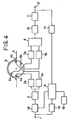
- FIGURE 4 is the block diagram showing the second embodiment of the present invention, with the same numbers assigned to the parts corresponding to those shown in FIGURE 1.
- the second embodiment differs from the first embodiment in that the relationship between input video signals to be recorded and rotation of the rotary drum 9 is controlled by controlling a variable delay circuit provided to delay video signals input to the video signal input terminal 1, and not by changing the rotation of the rotary drum 9. That is, the phase control signal that is output from the editing control circuit 15 is given to the variable delay circuit 18 as a delay time control signal.
- the variable delay circuit 18 is made up, for instance, using a semiconductor memory. Video signals being input are written into the memory after being digitized by, for instance, an A/D converter, and are read and outpt after being converted to analogue signals by a D/A converter. What is necessary in this case is that the editing phase control circuit 15 controls the write timing to a semiconductor memory according to the timing t1 of the synchronous signals separated from the input video signals by the synchronous separator 13 and controls the read timing from, the semiconductor memory according to a timing that is shifted from the timing t1 of the synchronous signals separated from the video signals reproduced from a position immediately before the editing start point by the synchronous separator 14 by the time difference ⁇ T stored in the memory 16. That is, it is sufficient to write video signals at the timing t1 and read at the timing t2 - ⁇ T.
- the embodiment shown in FIGURE 4 is excellent in response speed and phase control accuracy.
- FIGURE 5 is the block diagram showing a third embodiment of the present invention, which includes a means to measure a time difference to be stored in the memory 16.
- the reproduced signal that is output from the heads switching circuit 8 is connected to the "TAPE" side terminal 22 of a switching circuit 21 after compensation of the frequency characteristic is made by the equalizer 10.
- the "EE" side terminal 23 of the switching circuit 21 is connected with the output terminal of the FM modulation circuit 2.
- the operation of the switching circuit 21 is controlled by the measuring control circuit 24.
- the so-called simultaneous reproduction mode i.e., to monitor the recording state at the time of recording
- the "TAPE" side terminal 22 is selected.
- the "EE" side terminal 23 is selected.
- the mesuring control circuit 24 gives a pulse signal, synchronized with the rotary drum 9, to the switching circuit 21.
- the switching circuit 21 selects input video signals to be recorded and reproduced signals alternately and outputs them to the FM demodulation circuit 11.
- the reproduced video signals demodulated in the FM demodulation circuit 11 are sent to the video output terminal 12 and at the same time, input into the synchronous separator 14.
- the synchronous signals separated by the synchronous separator 14 are also supplied to the time difference measuring circuit 25.
- the time difference measuring circuit 25 is made up using a digital counter and measures the time difference between the synchronous signals in the input video signals supplied from the synchronous separator and the synchronous signals in the reproducing video signals based on the control signal and clock signal from the measuring control circuit 24.
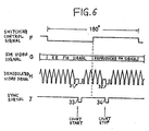
- FIGURE 6 is a timing chart showing the waveforms of the parts having symbols F-J in FIGURE 5 in "Time Difference Measuring Mode".
- F denotes the switching control signal that controls the switching operation of the switching circuit 21
- G denotes the FM video signal that is output from the switching circuit 21
- H denotes the video signal demodulated in the FM demodulation circuit 11
- J denotes the synchronous signals separated by the synchronous separator 13.
- the switching control signal F is a square wave signal of which one period is the time required for the rotary drum 9 to turn 180° and is inversed close to the middle the time between when the recording heads recorded the vertical synchronous signals of input video signal and the reproducing heads reproduced the same vertical synchronous signals.
- the switching control signal F is inversed about 22.5° after the recording heads recorded the vertical synchronous signals.
- the FM video signal G becomes the recorded FM signal (EE-FM) when the switching control signal F is at low level, while it becomes the reproduced FM signal at high level.
- the video signal H is the demodulated FM video signal G, 31 denotes the vertical synchronous signals in the input video signals, and 32 denotes the synchronous signals on the reproduced video signals.
- the synchronous signals J shows the vertical synchronous signals separated from the video signal H. 33 denotes the vertical synchronous signals in the input video signals, and 34 denotes the vertical synchronous signals in the reproduced video signals.
- the time difference measuring circuit 25 measures the time from the fall of the vertical synchronous signals 33 to the fall of the vertical synchronous signals 34 by counting clock signals from the measuring control circuit 24. The time measured in the time difference measuring circuit 25 is sent to the memory 16 and stored there at the fall of the switching control signal F.
- FIGURE 7 is the block diagram showing the fourth embodiment of the present invention and is identical to the embodiment shown in FIGURE 5 except that the relation between the phase of the input video signal to be recorded and the rotating phase of the rotary drum 9 is controlled by controlling the delay time of the variable delay circuit 18 as in the emboidment shown in FIGURE 4.
- time difference data stored in the memory 16 for applications other than phase control at the time of editing. For instance, it may be used for phase adjustment of the tachometer pulse of the rotary drum, control track position adjustment, etc. when adjusting VTR.
- either of the rotation of the rotary drum 9 or the delay time of the variable delay circuit 18 is controlled, but it is also possible to control both of them.
- the present invention it is possible to optimize the phase relation between signals to be recorded and the recording heads in a VTR which has separate record and reproduce heads at the time of editing similar to VTRs that are capable of reproducing signals on a magnetic tape by the recording heads. This helps to reduce discontinuity of the phases of video signals before and after the editing point on a magnetic tape.
Landscapes
- Engineering & Computer Science (AREA)
- Signal Processing (AREA)
- Multimedia (AREA)
- Management Or Editing Of Information On Record Carriers (AREA)
- Television Signal Processing For Recording (AREA)
Claims (9)
- Videosignal-Aufzeichnungs-/Wiedergabe-Gerät mit einer drehbaren Trommel (9), die mindestens einen Aufzeichnungskopf (4) zum Aufzeichnen von Eingangsvideosignalen auf einem Videoband und mindestens einen Wiedergabekopf (6) zum Wiedergeben von aufgezeichneten Videosignalen besitzt; mit ersten und zweiten Synchrontrennmitteln (13, 14) zum Ableiten von Synchronsignalen aus den Eingangsvideosignalen und den wiedergegebenen Videosignalen; mit Mitteln (15) zum Erkennen der Phasendifferenz zwischen den Synchronsignalen, die von den ersten und zweiten Synchronsignal-Trennmitteln erhalten wurden; und mit einem Phasensteuermittel, welches die erkannte Phasendifferenz zwischen den Synchronsignalen einsetzt, um das Synchronsignal des Eingangssignals mit dem Synchronsignal des aufgezeichneten Signals zu synchronisieren, dadurch gekennzeichnet, daß der Wiedergabekopf gegenüber dem Aufzeichnungskopf in Drehrichtung der Trommel versetzt ist; und durch Speichermittel (16) zum Speichern eines Differenzsignals, das den Versatzwinkel zwischen dem Aufzeichnungskopf und dem Wiedergabekopf auf der Trommel darstellt, wobei das Phasensteuermittel außerdem das gespeicherte Differenzsignal heranzieht und dadurch die Phasendifferenz ausgleicht, die durch den Versatzwinkel des Aufzeichnungs- und Wiedergabekopfs verursacht ist.
- Gerät nach Anspruch 1, wobei das Phasensteuermittel die Eingangsvideosignale verzögert.
- Gerät nach Anspruch 1, wobei das Phasensteuermittel die Drehung der drehbaren Trommel steuert.
- Gerät nach Anspruch 1, 2 oder 3, wobei das Speichermittel ein Zeitdifferenzsignal speichert, welches die Zeitverzögerung darstellt, in der eine vorgegebene Stelle auf dem Videoband von dem Wiedergabekopf zu dem Aufnahmekopf läuft.
- Gerät nach einem der vorhergehenden Ansprüche, wobei ein Paar von Aufzeichnungsköpfen um 180° beabstandet ist.
- Gerät nach einem der vorhergehenden Ansprüche, wobei ein Paar von Wiedergabeköpfen um 180° beabstandet ist.
- Gerät nach Anspruch 2, wobei eine variable Verzögerungseinrichtung die Eingangsvideosignale verzögert und wobei das Phasensteuermittel die variable Verzögerungseinrichtung steuert.
- Gerät nach Anspruch 1 mit einem Aufzeichnungsmittel zum Erzeugen von Aufzeichnungssignalen für den Aufzeichnungskopf in Abhängigkeit von den Eingangsvideosignalen; mit einem Demodulationsmittel zum Demodulieren von Signalen, die von dem Wiedergabekopf wiedergegeben werden, um reproduzierte Videosignale zu erzeugen; und mit Schaltmitteln zum selektiven Anlegen der aufgezeichneten Signale und der reproduzierten Signale an das Demoduliermittel, um das Differenzsignal zu messen.
- Gerät nach einem der vorhergehenden Ansprüche, wobei das erste und zweite Synchrontrennmittel die Vertikalsynchronsignale trennt.
Applications Claiming Priority (2)
| Application Number | Priority Date | Filing Date | Title |
|---|---|---|---|
| JP215606/88 | 1988-08-30 | ||
| JP63215606A JPH0264953A (ja) | 1988-08-30 | 1988-08-30 | 映像記録再生装置 |
Publications (3)
| Publication Number | Publication Date |
|---|---|
| EP0357352A2 EP0357352A2 (de) | 1990-03-07 |
| EP0357352A3 EP0357352A3 (de) | 1992-07-29 |
| EP0357352B1 true EP0357352B1 (de) | 1994-06-01 |
Family
ID=16675214
Family Applications (1)
| Application Number | Title | Priority Date | Filing Date |
|---|---|---|---|
| EP19890308650 Expired - Lifetime EP0357352B1 (de) | 1988-08-30 | 1989-08-25 | Videosignalaufzeichnungs-/-wiedergabegerät |
Country Status (3)
| Country | Link |
|---|---|
| EP (1) | EP0357352B1 (de) |
| JP (1) | JPH0264953A (de) |
| DE (1) | DE68915654T2 (de) |
Families Citing this family (1)
| Publication number | Priority date | Publication date | Assignee | Title |
|---|---|---|---|---|
| JP3093255B2 (ja) * | 1990-10-31 | 2000-10-03 | キヤノン株式会社 | ビデオ信号記録装置 |
Family Cites Families (4)
| Publication number | Priority date | Publication date | Assignee | Title |
|---|---|---|---|---|
| US3742132A (en) * | 1970-05-23 | 1973-06-26 | Nippon Electric Co | Drum servo system of a video tape recorder for an electronic editing |
| JPS5669981A (en) * | 1979-11-12 | 1981-06-11 | Sony Corp | Phase servo circuit |
| JPS57164466A (en) * | 1981-04-02 | 1982-10-09 | Sony Corp | Drum servo device of vtr |
| JPS648575A (en) * | 1987-06-30 | 1989-01-12 | Toshiba Corp | Video recording and reproducing device |
-
1988
- 1988-08-30 JP JP63215606A patent/JPH0264953A/ja active Pending
-
1989
- 1989-08-25 EP EP19890308650 patent/EP0357352B1/de not_active Expired - Lifetime
- 1989-08-25 DE DE1989615654 patent/DE68915654T2/de not_active Expired - Fee Related
Also Published As
| Publication number | Publication date |
|---|---|
| EP0357352A3 (de) | 1992-07-29 |
| DE68915654T2 (de) | 1994-09-15 |
| DE68915654D1 (de) | 1994-07-07 |
| EP0357352A2 (de) | 1990-03-07 |
| JPH0264953A (ja) | 1990-03-05 |
Similar Documents
| Publication | Publication Date | Title |
|---|---|---|
| US4237500A (en) | Method of controlling the position of a write-read head and device for carrying out the method | |
| US4739420A (en) | Method and apparatus for recording and reproducing a digital signal on a record medium using a rotary head | |
| GB2097968A (en) | Information signal reproducing apparatus | |
| US4533963A (en) | Video tape recorder for re-recording audio signals | |
| JPH02107079A (ja) | 磁気記録再生装置 | |
| EP0380284A1 (de) | Gerät und Verfahren zur Erzeugung von Spurregelsignalen | |
| US5016120A (en) | Apparatus for recording and reproducing a digitized audio signal on a magnetic tape which has a slant track format including means for detecting a control signal to identify a digitized audio signal on the slant track | |
| US5680499A (en) | Time-lapse video cassette recorder | |
| EP0587320B1 (de) | Signalwiedergabegerät | |
| EP0172441B1 (de) | Spurfolgeregelungssystem für ein Videobandaufnahmegerät | |
| EP0357352B1 (de) | Videosignalaufzeichnungs-/-wiedergabegerät | |
| EP0316954B1 (de) | Wiedergabeverfahren für Bandrekorder mit Drehkopf | |
| US5177649A (en) | Information signal recording apparatus for recording pilot signals on particular areas | |
| US5589997A (en) | Tracking control method and apparatus for video recorder which adds a combined first and second tracking error signal to the next tracking error signal | |
| US4191978A (en) | Method for adjusting rotary head type magnetic video recording and reproducing apparatus | |
| US5029021A (en) | Video recording/reproducing apparatus and method of editing video tape | |
| JPH1011844A (ja) | オートトラッキング装置 | |
| US5978171A (en) | Information signal reproducing apparatus with diverse mode tracking control | |
| JPS61187186A (ja) | 磁気テープの記録方法 | |
| JP3008712B2 (ja) | 磁気記録再生装置 | |
| US7046479B2 (en) | Magnetic recording/reproducing device having position control | |
| KR960001487B1 (ko) | 다이나믹 트래킹 재생장치 | |
| JP2799093B2 (ja) | 磁気記録再生装置 | |
| JPH0158567B2 (de) | ||
| JPH0652604A (ja) | データ記録再生装置 |
Legal Events
| Date | Code | Title | Description |
|---|---|---|---|
| PUAI | Public reference made under article 153(3) epc to a published international application that has entered the european phase |
Free format text: ORIGINAL CODE: 0009012 |
|
| 17P | Request for examination filed |
Effective date: 19890919 |
|
| AK | Designated contracting states |
Kind code of ref document: A2 Designated state(s): DE FR GB |
|
| PUAL | Search report despatched |
Free format text: ORIGINAL CODE: 0009013 |
|
| AK | Designated contracting states |
Kind code of ref document: A3 Designated state(s): DE FR GB |
|
| 17Q | First examination report despatched |
Effective date: 19930719 |
|
| GRAA | (expected) grant |
Free format text: ORIGINAL CODE: 0009210 |
|
| AK | Designated contracting states |
Kind code of ref document: B1 Designated state(s): DE FR GB |
|
| PG25 | Lapsed in a contracting state [announced via postgrant information from national office to epo] |
Ref country code: FR Effective date: 19940601 |
|
| REF | Corresponds to: |
Ref document number: 68915654 Country of ref document: DE Date of ref document: 19940707 |
|
| PGFP | Annual fee paid to national office [announced via postgrant information from national office to epo] |
Ref country code: FR Payment date: 19940809 Year of fee payment: 6 |
|
| EN | Fr: translation not filed | ||
| PLBE | No opposition filed within time limit |
Free format text: ORIGINAL CODE: 0009261 |
|
| STAA | Information on the status of an ep patent application or granted ep patent |
Free format text: STATUS: NO OPPOSITION FILED WITHIN TIME LIMIT |
|
| 26N | No opposition filed | ||
| PGFP | Annual fee paid to national office [announced via postgrant information from national office to epo] |
Ref country code: GB Payment date: 19960816 Year of fee payment: 8 |
|
| PG25 | Lapsed in a contracting state [announced via postgrant information from national office to epo] |
Ref country code: GB Free format text: LAPSE BECAUSE OF NON-PAYMENT OF DUE FEES Effective date: 19970825 |
|
| PGFP | Annual fee paid to national office [announced via postgrant information from national office to epo] |
Ref country code: DE Payment date: 19970901 Year of fee payment: 9 |
|
| GBPC | Gb: european patent ceased through non-payment of renewal fee |
Effective date: 19970825 |
|
| PG25 | Lapsed in a contracting state [announced via postgrant information from national office to epo] |
Ref country code: DE Free format text: LAPSE BECAUSE OF NON-PAYMENT OF DUE FEES Effective date: 19990601 |