EP0357497A2 - Entladungsverfahren in einem elektrophotographischen Gerät - Google Patents
Entladungsverfahren in einem elektrophotographischen Gerät Download PDFInfo
- Publication number
- EP0357497A2 EP0357497A2 EP89402347A EP89402347A EP0357497A2 EP 0357497 A2 EP0357497 A2 EP 0357497A2 EP 89402347 A EP89402347 A EP 89402347A EP 89402347 A EP89402347 A EP 89402347A EP 0357497 A2 EP0357497 A2 EP 0357497A2
- Authority
- EP
- European Patent Office
- Prior art keywords
- unit
- photosensitive member
- deelectrification
- optical
- electrification
- Prior art date
- Legal status (The legal status is an assumption and is not a legal conclusion. Google has not performed a legal analysis and makes no representation as to the accuracy of the status listed.)
- Granted
Links
Images




Classifications
-
- G—PHYSICS
- G03—PHOTOGRAPHY; CINEMATOGRAPHY; ANALOGOUS TECHNIQUES USING WAVES OTHER THAN OPTICAL WAVES; ELECTROGRAPHY; HOLOGRAPHY
- G03G—ELECTROGRAPHY; ELECTROPHOTOGRAPHY; MAGNETOGRAPHY
- G03G21/00—Arrangements not provided for by groups G03G13/00 - G03G19/00, e.g. cleaning, elimination of residual charge
- G03G21/06—Eliminating residual charges from a reusable imaging member
- G03G21/08—Eliminating residual charges from a reusable imaging member using optical radiation
-
- G—PHYSICS
- G03—PHOTOGRAPHY; CINEMATOGRAPHY; ANALOGOUS TECHNIQUES USING WAVES OTHER THAN OPTICAL WAVES; ELECTROGRAPHY; HOLOGRAPHY
- G03G—ELECTROGRAPHY; ELECTROPHOTOGRAPHY; MAGNETOGRAPHY
- G03G15/00—Apparatus for electrographic processes using a charge pattern
- G03G15/02—Apparatus for electrographic processes using a charge pattern for laying down a uniform charge, e.g. for sensitising; Corona discharge devices
- G03G15/0266—Arrangements for controlling the amount of charge
Definitions
- This invention relates to a method of controlling an optical-deelectrification in an electrophotographic recording apparatus, such as a printer, facsimile, or copying machine, having a photosensitive drum which is deelectrified by an optical irradiation thereto.
- This invention also relates to a method of pre-electrification in the same kind of electrophotographic recording apparatus.
- An electrophotgraphic recording apparatus is widely used in various printers, facsimiles, or copying machines, and such an electrophotgraphic recording apparatus includes many processing units, such as a photosensitive drum, a front electrification unit, a developing unit, a photo-depositing unit, a deelectrification unit, and a cleaner, and therefore, such an apparatus must have a large size.
- processing units such as a photosensitive drum, a front electrification unit, a developing unit, a photo-depositing unit, a deelectrification unit, and a cleaner, and therefore, such an apparatus must have a large size.
- processing units such as a photosensitive drum, a front electrification unit, a developing unit, a photo-depositing unit, a deelectrification unit, and a cleaner, and therefore, such an apparatus must have a large size.
- there is a strong demand for a reduction of the size of such an apparatus due to the current trend toward smaller office automation facilities.
- the respective processing units must be made compact and effectively arranged in the apparatus, and in this connection, a deelectrification unit can be more freely arranged than other units. Therefore, there is a demand for a small-sized optical-deelectrification unit. Note, this unit must be sometimes arranged at a position from which an optical-deelectrification beam is not directly irradiated to the photosensitive drum, but is irradiated to the drum via a printing media.
- An object of the present invention is to provide an optical-deelectrification control method in an electrophotographic recording apparatus, in which the voltage on the electrified surface of the photosensitive drum is not changed even if the drum is photo-deelectrified through a printing media, to obtain stable and high quality printed products.
- Another object of the present invention is to provide a method of pre-electrification in the same kind of electrophotographic recording apparatus, in which the voltage on the photosensitive drum can be always maintained at a desired high level.
- a method of controlling an optical-deelectrification in an electrophotographic recording apparatus comprising a rotatable photosensitive drum, a front electrification unit for electrifying the photosensitive drum, a photo-depositing unit for depositing an electrostatic latent image on the photosensitive drum, a developing unit for developing the latent image, a transfer electrification unit for transferring the image to printing media, an optical-deelectrification unit for deelectrifying the photosensitive drum, and a means of defining a passage of the printing media.
- the apparatus is characterized in that the optical deelectrification unit is located at a position opposite said photosensitive drum with respect to the passage of printing media, and an optical deelectrification beam is irradiated from the optical deelectrification unit to said photosensitive drum only when the printing media interrupts an optical path of the deelectrification beam toward the photosensitive drum.
- a pre-electrification method in an electrophotographic recording apparatus comprising a rotatable photosensitive drum and, along a rotational circumferential direction of the the drum, a front electrification unit for electrifying the photosensitive drum, a photo-depositing unit for depositing an electrostatic latent image on the photosensitive drum, a developing unit for developing the latent image, a transfer electrification unit for transferring the image to printing media, and a control means for effecting a printing operation according to a print start signal;
- this method is characterized in that, when the print start signal is received, a period from the time at which a previous printing operation has finished is measured, and if this measured period is larger than a predetermined period, the photosensitive drum is pre-electrified by the front electrification unit for at least one revolution of the photosensitive drum, before the printing operation is started.
- an electrophotographic recording apparatus includes a rotating photosensitive media or member, such as a drum or belt 1 which is electrified by a front electrification unit 2.
- a photodepositing unit 3 has a depositing element, such as a light emission diode (LED), to form on the photosensitive drum 1 an electrostatic latent image which is developed by a developing unit or sleeve 4.
- the toner image on the photosensitive drum 1 is transferred to a printing media or paper PP by a transfer electrification unit 5, and then the photosensitive drum 1 is deelectrified by an optical deelectrification unit 6 having an optical deelectrification element, such as a light emission diode (LED).
- the photosensitive drum 1 is then cleaned by a cleaner 7.
- the optical deelectrification unit 6 could be located at any position, preferably the unit 6 would be arranged at a position, from which a deelectrification laser beam is directly irradiated to the drum 1, to obtain an effective deelectrification.
- the deelectrification unit 6 must be sometimes located at a position of which the unit 6 does not interfere with the other units, such as a position opposite to the printing paper PP, from where a deelectrification laser beam is not directly irradiated to the photosensitive drum 1 but is irradiated to the drum 1 via the printing paper PP, as shown in Fig. 1B.
- a voltage at the surface of the drum 1 is reduced to about 400 V when a deelectrification optical beam is irradiated through the printing paper PP, but on the other hand, a voltage at the surface of the drum 1 is greatly reduced to nearly 0 V when a deelectrification optical beam is directly irradiated to the drum 1 and is not transmitted through the printing paper PP.
- the drum surface has two parts; one at which the voltage is greatly reduced and another at which the voltage is less reduced, as shown in Fig. 1C.
- the voltage on the drum surface to which the deelectrification optical light has been irradiated through the printing paper PP can be raised nearly to a saturated voltage of 600 V.
- the voltage on the drum surface to which the deelectrification optical beam has been directly irradiated is raised only to a value such as 550 V, which is lower than the saturated voltage, as showing in Fig. 1C. Due to such a voltage unbalance on the electrified drum surface, the lower voltage printed areas on the drum surface will be dark and will sometimes be shaded off.
- One method of realizing this is to reduce the intensity of the deelectrification beam from the deelectrification unit itself, by reducing an actuating voltage of small-sized deelectrification lamps (LED) or using LEDs having a lower output power.
- This method is not practical because a reduction of the amount of deelectrification beam is naturally limited to some extent.
- Another method is to reduce the number of deelectrification lamps (LED) from n to m (m ⁇ n), to reduced the total illumination of deelectrification beam. But this method is not preferable in that the amount of beam becomes uneven with respect to the axial direction of the photosensitive drum, if a plurality of such lamps are spacedly arranged along the axial direction thereof.
- Still another method is to remove the deelectrification unit itself, and not conduct such a deelectrification. But, according to the photosensitivity of the drum used for this purpose, the drum may be worn out after long term usage, so that the sensitivity or clearness of the printed products will be reduced.
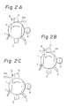
- FIG. 2A to 2C show a principle of this invention.
- a rotating photosensitive drum 1 is electrified by a front electrification unit 2.
- a photo-depositing unit 3 is provided with a depositing element to form on the photosensitive drum 1 an electrostatic latent image which is developed by a developing unit 4.
- the image on the photosensitive drum 1 is transferred to a printing media PP by a transferring unit 5.
- the photosensitive drum 1 is deelectrified by an optical deelectrification unit 6.
- the optical deelectrification unit 6 is located at a position opposite to the photosensitive drum 1 with respect to a passage of the moving printing media PP, as shown in Fig. 2A.
- a sensor (not shown in Figs. 2A-2C) is provided for detecting whether the printing media PP passes through the optical deelectrification unit 6, and the optical deelectrification unit 6 is controlled to irradiate an optical deelectrification beam to deelectrify the photosensitive drum 1 only when the moving printing media PP interferes with an optical path from the optical deelectrification unit 6 to the photosensitive drum 1, as shown in Figs. 2B and 2C.
- FIG. 3 illustrates an embodiment of an electrophotographic recording apparatus according to the present invention, in which the same parts as shown in Fig. 1 are indicated by the same reference numeral.
- a media sensor 8 is provided for detecting the printing media PP, which is picked up by a pickup roller 14 from the hopper 13 and moved by feed rollers 9 in a direction shown by an arrow.
- the printing media PP is then moved through and guided by a transfer guide roller 10 during a transfer operation at the transfer unit 5. Then, the printing media PP is moved through a guide member 11 and the toner image transferred to the printing media PP is fixed by fixing rollers 12.
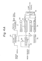
- FIG 4A is a block diagram illustrating a circuit for controlling the optical-deelectrification unit 6 according to this invention. Such a circuit is included as a part of the CPU 41 shown in Fig. 3.
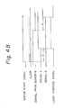
- Figure 4B is a diagram illustrating the wave shapes in various positions.
- a clock generator 20 generate clock signals for actuating step motors to drive the various parts of this electrophotographic recording apparatus, such as the feed rollers 9, the photosensitive drum 1, the developing sleeve 4, the fixing rollers 12, and so on, and a phase changing means 21 changes the phase of the step motors according to the clock signals.
- an AND gate 30 opens to output the clock signal from the clock generator 20, and a first counter 31 counts the clock signal from the AND gate 30.
- a first register 32 is used for registering a first reference value (a) corresponding to a distance A (Fig. 3) from a point C to the left end of the optical-deelectrification unit 6, and a first comparator 33 compares the counted value of the first counter 31 and the first reference value (a) of the first register 32 to output a lamp ON signal (A).
- An inverter 34 inverts the media sensor signal from the media sensor 8.
- an AND gate 35 opens to output the clock signal from the clock generator 20, and a second counter 36 counts the clock signal from the AND gate 35.
- a second register 37 is used for registering a second reference value (b) corresponding to a distance B (Fig. 3) from a point C to the right end of the optical-deelectrification unit 6, and a second comparator 38 compares the counted value of the second counter 36 and the second reference value (b) of the second register 37 to output a lamp OFF signal (B).
- a lamp actuating circuit 39 outputs to the optical-deelectrification unit 6 a lamp actuating signal which is turned ON by the lamp ON signal (A) and OFF by the lamp OFF signal (B).
- the leading end of the printing media PP is detected by the counter 31, register 32, and comparator 33, and the tailing end thereof is detected by the counter 36, register 37, and comparator 38.
- the printing media PP is picked up by a pickup roller 14 from the hopper 13 and detected when it passes through the media sensor 8.
- the clock generator 20 When the leading edge of the printing media PP arrives at a point C in Fig. 2, the printing media PP once stops.
- the clock generator 20 When a motor actuating signal is received, the clock generator 20 generates a clock signal to actuate the step motors via the phase changing means 21, and thus the feed rollers 9 are again driven to further feed the printing media PP.
- the first AND gate 30 opens and the second AND gate 35 is closed, and therefore, the first counter 31 counts a driving clock from the clock generator 20.
- the first comparator 33 compares the counted value of the first counter 31 and the first reference value (a) of the first register 32 corresponding to a distance A.
- the distance A is a distance through which the printing media PP travels from the feed rollers 9 to the optical-deelectrification unit 6, so that only an optical-deelectrification beam transmitted through the printing media PP is irradiated to the photosensitive drum 1.
- a lamp ON signal (A) is output from the first comparator 33 to the lamp actuating circuit 39, which outputs a lamp driving signal to turn ON the LED of the optical-deelectrification unit 6.
- a media detection signal is turned OFF to close the AND gate 30 and open the AND gate 35, and thus the second counter 36 counts a driving clock from the clock generator 20.
- the second comparator 38 compares the counted value of the second counter 36 and the second reference value (b) of the second register 37 corresponding to a distance B.
- This distance B is a distance through which the tailing end of the printing media PP travels from the media sensor 8 to a position just before the optical-deelectrification unit 6. Therefore, the optical-deelectrification beam is irradiated until just before the tailing end of the printing media PP reaches the optical-deelectrification unit 6.
- a lamp OFF signal (B) is output from the second comparator 38 to the lamp actuating circuit 39 to turn OFF the lamp driving signal and stop the irradiation from the optical-deelectrification unit 6.
- the front electrification unit 2 electrifies the photosensitive drum 1 and an image is deposited on the drum 1 by the photo-depositing unit 3.
- the developing sleeve 4 develop a toner image, which is transferred to the printing media PP by the transfer electrification unit 5 and then fixed by the fixing rollers 12.
- the optical-deelectrification unit 6 is controlled so that the optical-deelectrification beam is not directly irradiated to the photosensitive drum 1, but is irradiated thereto only through the printing media PP, because the clock signal from the clock generator 20 for driving the step motors is counted by the counters 31 and 36, and the leading and tailing edges of the printing media PP (i.e., the distance through which the printing media PP travels from the point C) are detected.
- the optical-deelectrification beam is not directly irradiated to the photosensitive drum 1 and thus an excess reduction of the voltage on the surface of the photosensitive drum 1 is prevented, so that the photosensitive drum 1 can easily be raised to a saturated voltage (such as, 600 V) when electrified by the front electrification unit 2. Therefore, the voltage of the electrified drum 1 becomes uniform over the entire surface thereof, and good quality printed products can be obtained.
- a saturated voltage such as, 600 V
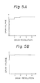
- Figures 5A and 5B show the relationships between the revolutional number of a photosensitive drum and a voltage on a surface of the drum which is electrified by a front electrification unit. If the apparatus has no deelectrification unit, or if the photosensitive drum cannot be fully deelectrified by a deelectrification unit, the voltage on the surface of the drum just before the front electrification unit is not always reduced to a required value. For example, if a print start signal is received a short time after the previous printing operations is finished, the voltage of the drum just before the front electrification unit is relatively high.
- the dru:a cannot reach a saturated voltage even if the drum is once electrified (one revolution), and the voltage thereof, must be raised step by step during several revolutions of the drum, as shown in Fig. 5A. If, however, the voltage of the drum is relatively high, the drum can reach almost a saturated voltage when the drum is once electrified (one revolution), as shown in Fig. 5B.
- Figure 6A illustrates a principle of an embodiment of this invention.
- the same reference numerals as used in Figs. 2A-2C indicate the same parts of the apparatus, except that this embodiment is provided with a control means 40.
- a print start signal is received, a check is carried out to detect whether or not a certain period has expired after the previous printing operation is finished. If a certain period has not expired since the previous printing operation, a pre-electrification is conducted before the printing operation is again started.
- the photosensitive drum 1 is rotated for one or more revolutions without conducting a printing operation, and is only pre-electrified by the front electrification unit 2 for at least one revolution of the drum 1.
- the printing operation is started after the voltage of the photosensitive drum 1 is fully raised to a saturated value (such as 600 V).
- the control means 40 comprises a processor (CPU) 41, having a timer T and a flag FL, for controlling the various parts of this electrophotographic recording apparatus by programs.
- a read memory (ROM) 42 memories the parameters or programs necessary for operating the CPU 41. Signals from the sensors 8 and 8a are input to an inlet/outlet port 43, which is also connected to the above-mentioned CPU 41 and a printer controller 45.
- a drive circuit 44 drives the front electrification unit 2, the photo-depositing unit 3, the developing sleeve 4, the motor MT, the transfer electrification unit 5, the optical deelectrification unit 6, and the fixing rollers 12 according to instructions from the CPU 20.
- Figure 7A is a flow chart for conducting a main process according to the present invention
- Fig. 7B is a flow chart for conducting a sub-process or pre-electrification process.
- the CPU 41 checks whether or not a print start signal has been received from the printer controller 45. After receiving a print command and print data, the controller 45 develops the print data to form print patterns and generates a print start signal when the preparation for printing is finished. After receiving the print start Signals the CPU 41 checks the flag FL.
- step (2) if the flag FL is ON, i.e., if a relatively long period has expired since the previous printing operation, the CPU 41 conducts a pre-electrification process as shown in Fig. 7B.
- the CPU turns on the motor driver of the drive circuit 44 to drive the motor MT, and thus the photosensitive drum 1, the developing sleeve 4, and so on are rotated.
- the CPU turns on the front electrification unit 2 via the drive circuit 44 to conduct a pre-electrification process and turns on the bias for developing, whereby the photosensitive drum 1 is pre-electrified by the front electrification unit 2.
- the CPU 41 checks whether the step number of the step motor MT has reached N, i.e., whether the photosensitive drum 1 has been rotated for a certain number of (for example, two) revolutions. After two revolutions of the drum 1, the CPU turns off the bias for developing and turns off the front electrification unit 2. Also, the motor driver is turned off to stop the motor MT to finish the pre-electrification process.
- the actuator 44 turns on the motor driver to rotate the motor MT.
- a clutch (not shown) of the hopper 13 is turned on, so that only the pickup roller 14 of the hopper is rotated by the motor MT to pickup the printing pattern from the hopper 13 and feed it to the feed roller 9.
- the CPU 41 checks whether the output signal form the sensor 8 is ON or OFF. If the signal is ON, i.e., if the printing paper has been fed to the feed roller 9 (at a waiting position), a set for printing paper is finished and thus the motor driver is turned off to stop the motor MT.
- the CPU 41 outputs to the printer controller 45, via the in/out port 43, a ready signal instructing that a preparation for printing is finished.
- the printer controller 45 outputs the print instructions and print pattern data to the CPU 41 via the in/out port 43.
- the CPU 41 turns on the motor driver of the actuator 44 to drive the motor MT to rotate the photosensitive drum 1, the developing unit 4, the feed rollers 9, and the fixing rollers 12.
- the front electrification unit 2 is turned on and the bias for developing, the transfer electrification unit 5, the optical deelectrification unit 6 and the fixing rollers 12 are turned on.
- the photo-depositing unit 3 is driven according to the print pattern data to form a toner image on the photosensitive drum 1, which is then transferred to the printing media PP fed by the feed rollers 9 and fixed at the fixing rollers 12 as a usual printing operation.
- the CPU 41 stops the actuator 44 to stop various parts of this printing apparatus, and thus the printing operations is finished.
- step (5) when the motor driver of the actuator 44 is turned off, the CPU 41 sets a predetermined time to the timer T and actuates the timer T.
- step (6) after the timer T is actuated, the CPU 41 checks whether a print start signal has been received from the printer controller 45. If such a signal has been received, the CPU 41 stops checking the timer and returns to step (3).
- step (7) contrary to the above, if such a signal has not been received, the CPU 41 checks whether the timer T has become 0. If the timer T has not become 0, the CPU 41 returns to step (6). On the other hand, if the timer T has become 0, the CPU 41 sets the flag FL to return to step (1).
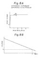
- Figures 8A and 8B are diagrams for explaining how to determine a set time t of the timer T.
- a voltage difference is small between one revolution and two or more revolutions of the photosensitive drum 1, as shown in Fig. 5B. But if such a voltage difference is larger than B, as shown in Figs. 5A or 8B, some problems will arise, such as the printed area will be dark and sometimes shaded off.
- a critical voltage difference B can be determined by experiment, and thus an initial voltage A also can be determined. Before the photosensitive drum 1 is electrified by the front electrification unit 2, if an initial voltage of the drum 1 is lower than A, the voltage difference B will be large and causes difficulties. On the other hand, if the initial voltage of the photosensitive drum 1 is higher than A, the voltage difference B will be small and no problems will arise.
- the dark attenuation characteristics of the photosensitive drum 1 can be measured and represented as Fig. 8B.
- the time T during which the voltage of the photosensitive drum 1 which has been initially electrified to a certain voltage is gradually reduced to A can be determined.
- such a time T depends on the conditions in use of an individual photosensitive drum, particularly a life thereof or a humidity of the environment. Therefore, it would be preferable to determine the time T in a humid condition with an old photosensitive drum near to an end of its life, so that as small as possible a set time t of the timer T can be obtained.
- a sensor 50 (Fig.3) is provided for detecting a voltage on the photosensitive drum 1 before the photosensitive drum 1 is electrified by the front electrification unit 2. If the measured voltage is lower than a predetermined value, i.e., if the voltage on the surface of the photosensitive drum 1 is reduced by more than a predetermined value, the photosensitive member 1 is pre-electrified by the front electrification unit 2 for at least one revolution of the photosensitive member, in the same manner as above.
Landscapes
- Physics & Mathematics (AREA)
- General Physics & Mathematics (AREA)
- Engineering & Computer Science (AREA)
- Plasma & Fusion (AREA)
- Health & Medical Sciences (AREA)
- Toxicology (AREA)
- Control Or Security For Electrophotography (AREA)
- Electrostatic Charge, Transfer And Separation In Electrography (AREA)
- Discharging, Photosensitive Material Shape In Electrophotography (AREA)
- Laser Beam Printer (AREA)
- Combination Of More Than One Step In Electrophotography (AREA)
Applications Claiming Priority (4)
| Application Number | Priority Date | Filing Date | Title |
|---|---|---|---|
| JP214391/88 | 1988-08-29 | ||
| JP21439188A JP2507551B2 (ja) | 1988-08-29 | 1988-08-29 | 電子写真装置の除電光制御方法 |
| JP217700/88 | 1988-08-31 | ||
| JP63217700A JP2510690B2 (ja) | 1988-08-31 | 1988-08-31 | 電子写真装置の予備帯電方法 |
Publications (3)
| Publication Number | Publication Date |
|---|---|
| EP0357497A2 true EP0357497A2 (de) | 1990-03-07 |
| EP0357497A3 EP0357497A3 (de) | 1991-07-24 |
| EP0357497B1 EP0357497B1 (de) | 1994-10-26 |
Family
ID=26520297
Family Applications (1)
| Application Number | Title | Priority Date | Filing Date |
|---|---|---|---|
| EP89402347A Expired - Lifetime EP0357497B1 (de) | 1988-08-29 | 1989-08-28 | Entladungsverfahren in einem elektrophotographischen Gerät |
Country Status (4)
| Country | Link |
|---|---|
| US (1) | US4985730A (de) |
| EP (1) | EP0357497B1 (de) |
| CA (1) | CA1327830C (de) |
| DE (1) | DE68919034T2 (de) |
Families Citing this family (4)
| Publication number | Priority date | Publication date | Assignee | Title |
|---|---|---|---|---|
| US5307121A (en) * | 1992-11-23 | 1994-04-26 | Eastman Kodak Company | Bi-functional charge neutralizer for electrostatographic copier/printer |
| US5530524A (en) * | 1993-03-09 | 1996-06-25 | Mita Industrial Co., Ltd. | Electrophotographic apparatus with photosensitive drum requiring multiple rotations for production of a copy image on one sheet and method of operating same |
| JP6260476B2 (ja) * | 2013-10-10 | 2018-01-17 | 京セラドキュメントソリューションズ株式会社 | 画像形成装置 |
| CN105739273B (zh) * | 2014-12-24 | 2019-01-04 | 株式会社理光 | 图像形成装置 |
Family Cites Families (13)
| Publication number | Priority date | Publication date | Assignee | Title |
|---|---|---|---|---|
| JPS5543564A (en) * | 1978-09-22 | 1980-03-27 | Ricoh Co Ltd | Electrophotographic copying method |
| JPS55151652A (en) * | 1979-05-17 | 1980-11-26 | Canon Inc | Electrophotographic apparatus |
| JPS55157756A (en) * | 1979-05-29 | 1980-12-08 | Canon Inc | Surface potential control unit |
| US4511240A (en) * | 1981-01-13 | 1985-04-16 | Canon Kabushiki Kaisha | Electrostatic recording apparatus |
| JPS59146082A (ja) * | 1983-02-09 | 1984-08-21 | Sharp Corp | 電子写真複写装置 |
| US4512652A (en) * | 1983-08-24 | 1985-04-23 | Xerox Corporation | Control scheme compensating for changing characteristics of a photoconductive member used in an electrophotographic printing machine |
| US4641158A (en) * | 1984-02-13 | 1987-02-03 | Canon Kabushiki Kaisha | Electrophotographic apparatus |
| DE3507312C2 (de) * | 1984-03-02 | 1990-06-21 | Sharp K.K., Osaka | Fotokopiergerät |
| JPS61221776A (ja) * | 1985-03-19 | 1986-10-02 | Sharp Corp | クリ−ニング前の除電装置 |
| JPS62187365A (ja) * | 1986-02-13 | 1987-08-15 | Ricoh Co Ltd | カラ−複写機 |
| JPS62226176A (ja) * | 1986-03-26 | 1987-10-05 | Toshiba Corp | 電子写真装置 |
| US4785324A (en) * | 1986-03-26 | 1988-11-15 | Kabushiki Kaisha Toshiba | Electrophotographic apparatus and method for preventing the lowering of a charging voltage at a photoreceptor |
| JPH0722675Y2 (ja) * | 1986-07-17 | 1995-05-24 | 三洋電機株式会社 | 電子写真装置 |
-
1989
- 1989-08-18 CA CA000608838A patent/CA1327830C/en not_active Expired - Fee Related
- 1989-08-22 US US07/396,877 patent/US4985730A/en not_active Expired - Lifetime
- 1989-08-28 DE DE68919034T patent/DE68919034T2/de not_active Expired - Lifetime
- 1989-08-28 EP EP89402347A patent/EP0357497B1/de not_active Expired - Lifetime
Also Published As
| Publication number | Publication date |
|---|---|
| US4985730A (en) | 1991-01-15 |
| DE68919034D1 (de) | 1994-12-01 |
| DE68919034T2 (de) | 1995-02-23 |
| EP0357497A3 (de) | 1991-07-24 |
| EP0357497B1 (de) | 1994-10-26 |
| CA1327830C (en) | 1994-03-15 |
Similar Documents
| Publication | Publication Date | Title |
|---|---|---|
| JPH03503575A (ja) | 調整される電子写真プロセスを有する電子写真印刷装置 | |
| US4534641A (en) | Charge erase device for copying or reproduction machines and printers | |
| US4696562A (en) | Multifunctional copying machine | |
| US5291225A (en) | Device for determining paper size based on time data | |
| EP0357497B1 (de) | Entladungsverfahren in einem elektrophotographischen Gerät | |
| US4561761A (en) | Charge erase device for copying or reproduction machines and printers | |
| US5210583A (en) | Electrophotographic printer which positions the leading edge of a recording sheet | |
| US4383753A (en) | Image formation apparatus | |
| US5512927A (en) | Image forming apparatus having a photosensitive drum rotatable at different speeds | |
| JP2005031431A (ja) | 画像形成装置 | |
| US4462679A (en) | Electronic copying machine | |
| KR100199474B1 (ko) | 전자사진 프린터의 장치의 용지 배면 오염 방지 제어방법 | |
| US4519697A (en) | Image forming apparatus | |
| JP3357470B2 (ja) | 画像形成方法及びその装置 | |
| JPS6241134A (ja) | 画像形成装置 | |
| JP2753380B2 (ja) | 電子写真装置 | |
| JP2782771B2 (ja) | 作像装置の異常検出装置 | |
| JPH0757654B2 (ja) | 記録装置及び画像の位置合せ方法 | |
| JPH08328437A (ja) | 電子写真装置 | |
| KR0174610B1 (ko) | 전자사진 현상방식을 이용하는 장치의 잼 제거방법 | |
| JP2898449B2 (ja) | 複写機用像担持体の位置検出装置 | |
| JPH04347870A (ja) | 画像形成装置および濃度検出器出力レベル調整方法 | |
| JPH0895433A (ja) | 画像形成装置 | |
| JP2524651B2 (ja) | 給紙搬送装置 | |
| JPS6193463A (ja) | 電子写真装置における黒枠除去方法 |
Legal Events
| Date | Code | Title | Description |
|---|---|---|---|
| PUAI | Public reference made under article 153(3) epc to a published international application that has entered the european phase |
Free format text: ORIGINAL CODE: 0009012 |
|
| AK | Designated contracting states |
Kind code of ref document: A2 Designated state(s): DE FR GB IT |
|
| PUAL | Search report despatched |
Free format text: ORIGINAL CODE: 0009013 |
|
| AK | Designated contracting states |
Kind code of ref document: A3 Designated state(s): DE FR GB IT |
|
| 17P | Request for examination filed |
Effective date: 19910910 |
|
| 17Q | First examination report despatched |
Effective date: 19921019 |
|
| ITF | It: translation for a ep patent filed | ||
| GRAA | (expected) grant |
Free format text: ORIGINAL CODE: 0009210 |
|
| AK | Designated contracting states |
Kind code of ref document: B1 Designated state(s): DE FR GB IT |
|
| REF | Corresponds to: |
Ref document number: 68919034 Country of ref document: DE Date of ref document: 19941201 |
|
| ET | Fr: translation filed | ||
| PLBE | No opposition filed within time limit |
Free format text: ORIGINAL CODE: 0009261 |
|
| STAA | Information on the status of an ep patent application or granted ep patent |
Free format text: STATUS: NO OPPOSITION FILED WITHIN TIME LIMIT |
|
| 26N | No opposition filed | ||
| REG | Reference to a national code |
Ref country code: GB Ref legal event code: IF02 |
|
| REG | Reference to a national code |
Ref country code: GB Ref legal event code: 732E |
|
| REG | Reference to a national code |
Ref country code: FR Ref legal event code: TP |
|
| PGFP | Annual fee paid to national office [announced via postgrant information from national office to epo] |
Ref country code: DE Payment date: 20080912 Year of fee payment: 20 |
|
| PGFP | Annual fee paid to national office [announced via postgrant information from national office to epo] |
Ref country code: FR Payment date: 20080818 Year of fee payment: 20 Ref country code: IT Payment date: 20080827 Year of fee payment: 20 |
|
| PGFP | Annual fee paid to national office [announced via postgrant information from national office to epo] |
Ref country code: GB Payment date: 20080903 Year of fee payment: 20 |
|
| REG | Reference to a national code |
Ref country code: GB Ref legal event code: PE20 Expiry date: 20090827 |
|
| PG25 | Lapsed in a contracting state [announced via postgrant information from national office to epo] |
Ref country code: GB Free format text: LAPSE BECAUSE OF EXPIRATION OF PROTECTION Effective date: 20090827 |