EP0357584A1 - Zapfwellengetriebe,insbesondere für die Frontzapfwelle von Ackerschleppern od. dgl. - Google Patents
Zapfwellengetriebe,insbesondere für die Frontzapfwelle von Ackerschleppern od. dgl. Download PDFInfo
- Publication number
- EP0357584A1 EP0357584A1 EP89890165A EP89890165A EP0357584A1 EP 0357584 A1 EP0357584 A1 EP 0357584A1 EP 89890165 A EP89890165 A EP 89890165A EP 89890165 A EP89890165 A EP 89890165A EP 0357584 A1 EP0357584 A1 EP 0357584A1
- Authority
- EP
- European Patent Office
- Prior art keywords
- wheel
- shaft
- pto
- output
- gear
- Prior art date
- Legal status (The legal status is an assumption and is not a legal conclusion. Google has not performed a legal analysis and makes no representation as to the accuracy of the status listed.)
- Granted
Links
- 238000009313 farming Methods 0.000 title 1
- 230000005540 biological transmission Effects 0.000 claims description 12
- 238000000926 separation method Methods 0.000 description 5
- 230000009977 dual effect Effects 0.000 description 2
- 238000004519 manufacturing process Methods 0.000 description 2
- 238000010276 construction Methods 0.000 description 1
- 230000007812 deficiency Effects 0.000 description 1
- 230000002349 favourable effect Effects 0.000 description 1
- 238000009434 installation Methods 0.000 description 1
- 230000007704 transition Effects 0.000 description 1
Images



Classifications
-
- B—PERFORMING OPERATIONS; TRANSPORTING
- B60—VEHICLES IN GENERAL
- B60K—ARRANGEMENT OR MOUNTING OF PROPULSION UNITS OR OF TRANSMISSIONS IN VEHICLES; ARRANGEMENT OR MOUNTING OF PLURAL DIVERSE PRIME-MOVERS IN VEHICLES; AUXILIARY DRIVES FOR VEHICLES; INSTRUMENTATION OR DASHBOARDS FOR VEHICLES; ARRANGEMENTS IN CONNECTION WITH COOLING, AIR INTAKE, GAS EXHAUST OR FUEL SUPPLY OF PROPULSION UNITS IN VEHICLES
- B60K25/00—Auxiliary drives
- B60K25/02—Auxiliary drives directly from an engine shaft
-
- F—MECHANICAL ENGINEERING; LIGHTING; HEATING; WEAPONS; BLASTING
- F16—ENGINEERING ELEMENTS AND UNITS; GENERAL MEASURES FOR PRODUCING AND MAINTAINING EFFECTIVE FUNCTIONING OF MACHINES OR INSTALLATIONS; THERMAL INSULATION IN GENERAL
- F16H—GEARING
- F16H3/00—Toothed gearings for conveying rotary motion with variable gear ratio or for reversing rotary motion
- F16H3/02—Toothed gearings for conveying rotary motion with variable gear ratio or for reversing rotary motion without gears having orbital motion
- F16H3/20—Toothed gearings for conveying rotary motion with variable gear ratio or for reversing rotary motion without gears having orbital motion exclusively or essentially using gears that can be moved out of gear
- F16H3/22—Toothed gearings for conveying rotary motion with variable gear ratio or for reversing rotary motion without gears having orbital motion exclusively or essentially using gears that can be moved out of gear with gears shiftable only axially
- F16H3/30—Toothed gearings for conveying rotary motion with variable gear ratio or for reversing rotary motion without gears having orbital motion exclusively or essentially using gears that can be moved out of gear with gears shiftable only axially with driving and driven shafts not coaxial
- F16H3/32—Toothed gearings for conveying rotary motion with variable gear ratio or for reversing rotary motion without gears having orbital motion exclusively or essentially using gears that can be moved out of gear with gears shiftable only axially with driving and driven shafts not coaxial and an additional shaft
Definitions
- the invention relates to a PTO gearbox, in particular for the front PTO of agricultural tractors or the like, with an input shaft that can be coupled to the drive motor, an output shaft that forms the PTO shaft stub and rotationally fixedly arranged input and output wheels on the input and output shafts.
- front and rear PTOs have mostly been driven in the same direction, namely clockwise rotation in the direction of travel, which can be carried out with the least technical effort, but requires a reversing gearbox when using attachments alternately on the rear or front with the resulting change in drive direction.
- the invention is therefore based on the object to eliminate these deficiencies and to provide a PTO transmission of the type described, which allows the drive of a PTO stub with different directions of rotation and different speeds, as well as a complete mechanical separation from the drive motor, and which is also relatively small Construction and design effort and especially characterized by its short overall length.
- the invention solves this problem in that the input shaft receives a sliding wheel as a drive wheel, that the output shaft carries two driven gears located next to each other, that a double wheel loosely mounted on an intermediate shaft meshes with one of the driven gears and that the sliding wheel is shifted from one exemption in two Switching positions can be shifted, in one of which it engages in the free driven wheel and in the other one it engages in the free wheel of the double wheel.
- the PTO stub can be driven clockwise or counterclockwise by simply moving the sliding wheel, or it can be completely mechanically separated from the input shaft in the release position. Depending on the equipment and choice of gear sizes, the desired speed of the PTO stub can be freely selected for both directions of rotation.
- the two driven wheels can be arranged directly next to one another on the output shaft, so that despite the switching option, the distance from the gear flange surface to the stub end remains minimal and the The short overall length required for the desired tight mounting position of the attachment results in which narrow mounting position results in a more favorable front axle load, a better overview and a lower device overhang.
- the double gear meshes with the driven gear which is farther from the PTO shaft stub and overlaps the other driven gear adjacent to the stub, the sliding gear preferably being in its release between the wheel of the dual gear assigned to it and the driven gear assigned to it, since so the double wheel extends from the rear driven wheel to the PTO stub towards the front, making the transmission particularly short.
- a further idler gear is mounted on the double gear, which meshes with the driven gear assigned to the sliding gear and into which the sliding gear engages in its one switching position instead of in the driving gear, the PTO shaft stub can be driven counterclockwise in two speeds, which was also previously not possible.
- a front PTO shaft gear 1 which has an input shaft 2 which can be coupled to the tractor drive motor and an output shaft 4 which forms the PTO shaft stub 3.
- a sliding wheel 5, which serves as a drive wheel is seated in a rotationally fixed manner and can be displaced into an exemption and two switching positions via a switching device 6.
- the output shaft 4 receives two output gears 7, 8 arranged directly next to one another, which can be of different dimensions and, on the one hand, can be directly connected to the sliding wheel 5 via a double wheel 9.
- the double wheel 9 is loosely supported by its two individual wheels 10, 11 on an intermediate shaft 12, one wheel 10 of the double wheel 9 constantly meshing with the driven wheel 8 which is farther from the PTO shaft stub 3 and the other wheel 11 of the double wheel 9 overlapping the sliding wheel 5 in one of the Switch positions with the sliding wheel 5 comes into engagement. In the other switching position, the sliding wheel 5 engages directly in the driven wheel 7 adjacent to the PTO stub 3, the release of the sliding wheel 5 being located between these two switching positions.
- a further idler gear 13 can be mounted on the double gear 9, which in turn meshes constantly with the driven gear 7 and instead of this driven gear 7 is assigned to the sliding gear 5 in the one switching position, so that the sliding gear 5 with none of the Output wheels 7, 8 meshes more directly, but in one switching position with one wheel 11 of the double wheel 9 and in the other switching position with the idler gear 13, whereby two different speed levels can be switched while the direction of rotation of the output shaft 4 remains the same.
- the front PTO transmission 1 can be offered in different design variants, the components remaining essentially the same except for the gears to be dimensioned differently.
- the PTO shaft 1 is simply designed for a PTO shaft that rotates clockwise in the direction of travel and can be driven at a specific speed, preferably 1000 rpm.
- the gearbox only needs to be equipped with the sliding wheel 5 itself and a single driven wheel 7, the sliding wheel and driven wheel giving the desired reduction and the sliding wheel 5 being switchable from one switch position to the release for the complete mechanical separation of the drive train.
- the PTO shaft stub 3 can be driven at a speed, preferably 1000 rpm, clockwise or counterclockwise, for which purpose the PTO shaft 1 comprises two drive wheels 7, 8 of the same size and a corresponding double wheel 9 in addition to the sliding wheel 5.
- the direction of rotation of the PTO shaft stub 3 is changed by switching the sliding wheel 5 from one to the other switching position at a constant speed.
- driven gears 7, 8a and a double gear 9a matched to the sliding wheel 5 so that in one shift position the PTO stub 3 rotates clockwise at a higher speed, for example 1000 rpm, and in the other shift position counterclockwise at lower speed, for example 540 rpm, is driven.
- the PTO transmission 1 illustrated in FIG. 7 has a PTO stub 3 which only rotates to the left and accordingly has only one output gear 8a which meshes with the wheel 10a of the double gear 9a, the desired speed, for example 1000 rpm or 540 rpm, being provided by suitable dimensioning of the wheels. min, can be selected.
- the sliding wheel 5 can only be brought into a switching position in which it meshes with the free wheel 11 of the double wheel 9a.
- Fig. 8 shows a PTO transmission 1, which has a left-rotating PTO stub 3 which can be driven at two different speeds, preferably 1000 rpm and 540 rpm, for which purpose it also has the sliding wheel 5, the two driven wheels 7, 8a and the double wheel 9a the idler gear 13 mounted on the double gear 9a.
- the two differently sized output gears 7, 8a mesh on the one hand with the one wheel 10a of the double wheel 9a, on the other hand with the idler gear 13 and the sliding wheel 5 can be in its two switching positions once with the idler gear 13, the other time with the free gear 11 of the dual gear 9 engage so that there is a left turn of the PTO stub at a speed determined by the switching positions.
- the release of the sliding wheel 5 entails a complete mechanical separation of the PTO stub 3 from the drive motor.
- the PTO transmission according to the invention is characterized by its wide range of applications and can be adapted to the most varied of requirements in the most economical manner. This results in a relatively low manufacturing effort and, above all, a very short overall length.
Landscapes
- Engineering & Computer Science (AREA)
- General Engineering & Computer Science (AREA)
- Mechanical Engineering (AREA)
- Chemical & Material Sciences (AREA)
- Combustion & Propulsion (AREA)
- Transportation (AREA)
- Arrangement And Driving Of Transmission Devices (AREA)
Abstract
Description
- Die Erfindung bezieht sich auf ein Zapfwellengetriebe, insbesondere für die Frontzapfwelle von Ackerschleppern od.dgl., mit einer an den Antriebsmotor ankuppelbaren Eingangswelle, einer den Zapfwellenstummel bildenden Ausgangswelle und drehfest auf den Ein- und Ausgangswellen angeordneten An- und Abtriebsrädern.
- Bisher werden Front- und Heckzapfwellen meist gleichsinnig, nämlich in Fahrtrichtung rechtsrehend angetrieben, was zwar mit geringstem technischem Aufwand durchführbar ist, aber bei wechselweisem heck- oder frontseitigem Einsatz von Anbaugeräten mit der dabei auftretenden Änderung der Antriebsrichtung ein Umkehrgetriebe verlangt. Zur Vermeidung dieser Umkehrgetriebe gehen nun Normierungsbestrebungen dahin, Antriebsrichtung und Drehzahl der Frontzapfwellen zu vereinheitlichen und neben einer in Fahrtrichtung mit 540 U/min oder 1000 U/min rechtsdrehenden Heckzapfwelle (gültige DIN-Norm) eine in Fahrtrichtung mit 1000 U/min linksdrehende Frontzapfwelle (vorgeschlagene DIN-Norm) vorzusehen, so daß zumindest in der Übergangszeit, bis die Vereinheitlichung erreicht ist, die Zapfwellengetriebe aus wirtschaftlichen Gründen verschiedene Anforderungen erfüllen und je nach Bedarf rechts- oder linksdrehende Zapfwellenstummel mit ein oder zwei Drehzahlstufen bieten sollten. Um dies zu erreichen, ist es bisher notwendig, Zapfwellengetriebe mit zwei gegensinnig drehenden Zapfwellenstummeln zu bauen, wobei auch die Drehzahlen der beiden Stummeln unterschiedlich sein können, ein Umschalten aber zur Änderung der Drehzahlen nicht möglich ist, da der Einbau einer Schalteinrichtung zu aufwendig und platzraubend wäre. Hiezu kommt noch, daß bei den bekannten Zapfwellenantrieben für eine vollständige mechanische Trennung des Antreibsstranges eine außerhalb des Zapfwellengetriebes angeordnete zusätzliche Schiebemuffe od.dgl. vorgesehen sein muß. Diese mechanische Trennung ist deshalb erwünscht, weil das Zapfwellengetriebe vorwiegend über eine Lamellenkupplung mit dem Antriebsmotor in Verbindung steht und über diese Lamellenkupplungen auch im ausgekuppelten Zustand noch ein gewisses Restmoment übertragen wird, das beispielsweise ein Starten mit angekuppeltem Gerät vor allem in kalter Jahreszeit be- oder gar verhindert.
- Der Erfindung liegt daher die Aufgabe zugrunde, diese Mängel zu beseitigen und ein Zapfwellengetriebe der eingangs geschilderten Art zu schaffen, das den Antrieb eines Zapfwellenstummels mit unterschiedlichem Drehsinn und unterschiedlicher Drehzahl sowie eine vollständige mechanische Trennung vom Antriebsmotor erlaubt und das sich darüber hinaus durch seinen verhältnismäßig geringen Bau- und Konstruktionsaufwand und vor allem auch durch seine geringe Baulänge auszeichnet.
- Die Erfindung löst diese Aufgabe dadurch, daß die Eingangswelle ein Schieberad als Antriebsrad aufnimmt, daß die Ausgangswelle zwei nebeneinander sitzende Abtriebsräder trägt, daß ein auf einer Zwischenwelle lose gelagertes Doppelrad mit einem der Abtriebsräder kämmt und daß das Schieberad über eine Schalteinrichtung aus einer Freistellung in zwei Schaltstellungen verschiebbar ist, in deren einer es in das freie Abtriebsrad und in deren anderer es in das freie Rad des Doppelrades eingreift. Durch ein einfaches Verschieben des Schieberades läßt sich der Zapfwellenstummel rechtslaufend oder linkslaufend antreiben oder in der Freistellung vollständig mechanisch von der Eingangswelle trennen. Je nach Ausstattung und Wahl der Zahnradgrößen ist dabei die gewünschte Drehzahl des Zapfwellenstummels für beide Drehrichtungen frei vorwählbar. Da das Schieberad auf der Eingangswelle sitzt, können die beiden Abtriebsräder auf der Ausgangswelle unmittelbar nebeneinander angeordnet sein, so daß trotz der Schaltmöglichkeit der Abstand von der Getriebeflanschfläche bis zum Stummelende minimal bleibt und sich die für die gewünschte enge Anbaulage des Anbaugerätes erforderliche kurze Baulänge ergibt, welche enge Anbaulage eine günstigere Vorderachsbelastung, eine bessere Übersichtlichkeit und einen geringeren Geräteüberstand mit sich bringt. Das Freistellen des Schieberades erübrigt den Einbau einer zusätzlichen mechanischen Trennkupplung und trotz der Schaltbarkeit und den verschiedensten Ausführungsvarianten des Getriebes bietet sich die Möglichkeit einer sehr wirtschaftlichen Fertigung, da für alle wählbaren Varianten viele Gleichteile, wie Gehäuse, Gehäusedeckel, Eingangswelle, Ausgangswelle, Zwischenwelle, Schalteinrichtung u.dgl. vorhanden sind und nur jeweils das Schieberad, die beiden Abtriebsräder und das Doppelrad auf die einzelnen Varianten speziell abgestimmt sein müssen.
- Besonders vorteilhaft ist es auch, wenn erfindungsgemäß das Doppelrad mit dem vom Zapfwellenstummel entfernteren Abtriebsrad kämmt und das dem Stummel benachbarte andere Abtriebsrad übergreift, wobei vorzugsweise das Schieberad in seiner Freistellung zwischen dem ihm zugeordneten Rad des Doppelrades und dem ihm zugeordneten Abtriebsrad liegt, da sich so das Doppelrad vom hinteren Abtriebsrad zum Zapfwellenstummel hin nach vorne erstreckt und das Getriebe dadurch besonders kurz baut.
- Ist nach einer zweckmäßigen Ausgestaltung der Erfindung auf dem Doppelrad ein weiteres Losrad gelagert, das mit dem dem Schieberad zugeordneten Abtriebsrad kämmt und in das statt in das Antriebsrad auch das Schieberad in seiner einen Schaltstellung eingreift, kann der Zapfwellenstummel linksdrehend in zwei Drehzahlstufen angetrieben werden, was bisher ebenfalls nicht möglich war.
- In der Zeichnung ist der Erfindungsgegenstand schematisch veranschaulicht, und zwar zeigen
- Fig. 1 ein erfindungsgemäßes Zapfwellengetriebe im Axialschnitt nach der Linie I-I der Fig. 2,
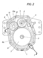
- Fig. 2 eine Stirnansicht dieses Getriebes ohne Deckel,
- Fig. 3 eine Ausführungsvariante des erfindungsgemäßen Zapfwellengetriebes im Axialschnitt entsprechend Fig. 1, die
- Fig. 4 bis 7 vier Ausführungsschemata des Getriebes nach Fig. 1 und 2 und
- Fig. 8 ein Ausführungsschema des Getriebes gemäß Fig. 3.
- Um einen nicht weiter dargestellten Ackerschlepper mit einer wahlweise nach beiden Drehrichtungen und mit verschiedenen Drehzahlen antreibbaren Frontzapfwelle ausrüsten zu können, ist ein Frontzapfwellengetriebe 1 vorgesehen, das eine an den Schlepperantriebsmotor ankuppelbare Eingangswelle 2 und eine den Zapfwellenstummel 3 bildende Ausgangswelle 4 aufweist. Auf der Eingangswelle 2 sitzt drehfest ein als Antriebsrad dienendes Schieberad 5, das über eine Schalteinrichtung 6 in eine Freistellung und zwei Schaltstellungen verschiebbar ist. Die Ausgangswelle 4 nimmt zwei unmittelbar nebeneinander angeordnete Abtriebsräder 7, 8 auf, die unterschiedlich dimensioniert sein können und einerseits direkt, anderseits über ein Doppelrad 9 mit dem Schieberad 5 antriebsverbindbar sind. Das Doppelrad 9 lagert mit seinen beiden Einzelrädern 10, 11 lose auf einer Zwischenwelle 12, wobei das eine Rad 10 des Doppelrades 9 ständig mit dem vom Zapfwellenstummel 3 entfernteren Abtriebsrad 8 kämmt und das andere Rad 11 des das Schieberad 5 übergreifenden Doppelrades 9 in einer der Schaltstellungen mit dem Schieberad 5 in Eingriff kommt. In der anderen Schaltstellung greift das Schieberad 5 direkt in das dem Zapfwellenstummel 3 benachbarte Abtriebsrad 7 ein, wobei sich zwischen diesen beiden Schaltstellungen die Freistellung des Schieberades 5 befindet.
- Wie in Fig. 3 angedeutet, kann auf dem Doppelrad 9 ein weiteres Losrad 13 gelagert sein, das seinerseits ständig mit dem Abtriebsrad 7 kämmt und statt dieses Abtriebsrades 7 in der einen Schaltstellung dem Schieberad 5 zugeordnet ist, so daß das Schieberad 5 mit keinem der Abtriebsräder 7, 8 mehr direkt kämmt, sondern in der einen Schaltstellung mit dem einen Rad 11 des Doppelrades 9 und in der anderen Schaltstellung mit dem Losrad 13 kämmt, wodurch sich bei gleichbleibender Drehrichtung der Ausgangswelle 4 zwei unterschiedliche Drehzahlstufen schalten lassen.
- Das Frontzapfwellengetriebe 1 kann in unterschiedlichen Ausführungsvarianten angeboten werden, wobei im wesentlichen bis auf die entsprechend unterschiedlich zu dimensionierenden Zahnräder die Bauteile gleichbleiben.
- Gemäß Fig. 4 ist das Zapfwellengetriebe 1 einfach für eine in Fahrtrichtung rechtsdrehende, mit einer bestimmten Drehzahl, vorzugsweise 1000 U/min, antreibbare Zapfwelle ausgelegt. Dazu braucht das Getriebe nur mit dem Schieberad 5 selbst und einem einzigen Abtriebsrad 7 ausgerüstet zu werden, wobei Schieberad und Abtriebsrad die gewünschte Untersetzung ergeben und das Schieberad 5 aus der einen Schaltstellung in die Freistellung zur vollständigen mechanischen Trennung des Antriebsstranges schaltbar ist.
- Beim Zapfwellengetriebe gemäß Fig. 5 läßt sich der Zapfwellenstummel 3 mit einer Drehzahl, vorzugsweise 1000 U/min, rechtsdrehend oder linksdrehend antreiben, wozu das Zapfwellengetriebe 1 neben dem Schieberad 5 zwei Antriebsräder 7, 8 gleicher Größe und ein entsprechendes Doppelrad 9 umfaßt. Neben der Freistellung des Schieberades 5 wird durch Umschalten des Schieberades 5 von der einen in die andere Schaltstellung bei gleichbleibender Drehzahl die Drehrichtung des Zapfwellenstummels 3 geändert.
- Beim Getriebe nach Fig. 6 gibt es dem Schieberad 5 zugeordnete unterschiedlich dimensionierte Abtriebsräder 7, 8a und ein darauf abgestimmtes Doppelrad 9a, so daß in der einen Schaltstellung der Zapfwellenstummel 3 rechtsdrehend mit höherer Drehzahl, beispielsweise 1000 U/min, und in der anderen Schaltstellung linksdrehend mit geringerer Drehzahl, beispielsweise 540 U/min, angetrieben wird.
- Das in Fig. 7 veranschaulichte Zapfwellengetriebe 1 bietet einen nur linksdrehenden Zapfwellenstummel 3 und weist dementsprechend nur ein mit dem Rad 10a des Doppelrades 9a kämmendes Abtriebsrad 8a auf, wobei durch geeignete Dimensionierung der Räder die gewünschte Drehzahl, beispielsweise 1000 U/min oder 540 U/min, gewählt werden kann. Das Schieberad 5 läßt sich hier neben seiner Freistellung nur in eine Schaltstellung bringen, in der es mit dem freien Rad 11 des Doppelrades 9a kämmt.
- Fig. 8 zeigt ein Zapfwellengetriebe 1, das einen mit zwei verschiedenen Drehzahlen, vorzugsweise 1000 U/min und 540 U/min, antreibbaren linksdrehenden Zapfwellenstummel 3 besitzt, wozu es außer dem Schieberad 5, den beiden Abtriebsrädern 7, 8a und dem Doppelrad 9a noch das auf dem Doppelrad 9a gelagerte Losrad 13 gibt. Die beiden unterschiedlich großen Abtriebsräder 7, 8a kämmen einerseits mit dem einen Rad 10a des Doppelrades 9a, anderseits mit dem Losrad 13 und das Schieberad 5 läßt sich in seinen beiden Schaltstellungen einmal mit dem Losrad 13, das andere Mal mit dem freien Rad 11 des Doppelrades 9 in Eingriff bringen, so daß es jeweils zu einer Linksdrehung des Zapfwellenstummels mit einer durch die Schaltstellungen bestimmten Drehzahl kommt. Auch hier bringt selbstverständlich, wie in allen anderen Varianten auch, die Freistellung des Schieberades 5 eine vollständige mechanische Trennung des Zapfwellenstummels 3 vom Antriebsmotor mit sich.
- Das erfindungsgemäße Zapfwellengetriebe zeichnet sich durch seinen breiten Anwendungsbereich aus und läßt sich in wirtschaftlichster Weise den verschiedensten Anforderungen anpassen. Dabei kommt es zu einem verhältnismäßig geringen Herstellungsaufwand und vor allem auch zu einer recht kurzen Baulänge.
Claims (3)
daß die Eingangswelle (2) ein Schieberad (5) als Antriebsrad aufnimmt,
daß die Ausgangswelle (4) zwei nebeneinander sitzende Abtriebsräder (7, 8, 8a) trägt,
daß ein auf einer Zwischenwelle (12) lose gelagertes Doppelrad (9, 9a) mit einem der Abtriebsräder (8, 8a) kämmt und
daß das Schieberad (5) über eine Schalteinrichtung (6) aus einer Freistellung in zwei Schaltstellungen verschiebbar ist, in deren einer es in das freie Abtriebsrad (7) und in deren anderer es in das freie Rad (11) des Doppelrades (9, 9a) eingreift.
Applications Claiming Priority (2)
| Application Number | Priority Date | Filing Date | Title |
|---|---|---|---|
| AT156388A AT399316B (de) | 1988-06-16 | 1988-06-16 | Zapfwellengetriebe, insbesondere für die frontzapfwelle von ackerschleppern od. dgl. |
| AT1563/88 | 1988-06-16 |
Publications (2)
| Publication Number | Publication Date |
|---|---|
| EP0357584A1 true EP0357584A1 (de) | 1990-03-07 |
| EP0357584B1 EP0357584B1 (de) | 1992-04-15 |
Family
ID=3516110
Family Applications (1)
| Application Number | Title | Priority Date | Filing Date |
|---|---|---|---|
| EP19890890165 Expired - Lifetime EP0357584B1 (de) | 1988-06-16 | 1989-06-15 | Zapfwellengetriebe,insbesondere für die Frontzapfwelle von Ackerschleppern od. dgl. |
Country Status (3)
| Country | Link |
|---|---|
| EP (1) | EP0357584B1 (de) |
| AT (1) | AT399316B (de) |
| DE (1) | DE58901155D1 (de) |
Cited By (10)
| Publication number | Priority date | Publication date | Assignee | Title |
|---|---|---|---|---|
| RU2137620C1 (ru) * | 1997-03-27 | 1999-09-20 | Общество с ограниченной ответственностью "КОМ" | Коробка отбора мощности |
| RU2348846C1 (ru) * | 2007-06-08 | 2009-03-10 | Государственное учреждение Всероссийский научно-исследовательский институт птицеперерабатывающей промышленности (ГУ ВНИИПП) | Кулачковый пространственный механизм |
| RU2381915C2 (ru) * | 2004-06-18 | 2010-02-20 | СКАНИА СВ АБ (пабл) | Способ и система для получения определенного передаточного отношения, а также держатель опоры |
| CN102927218A (zh) * | 2012-11-02 | 2013-02-13 | 无锡华联科技集团有限公司 | 管子倒角机传动箱机构 |
| CN102943848A (zh) * | 2012-11-12 | 2013-02-27 | 江苏省无锡探矿机械总厂有限公司 | 回转器变速机构 |
| CN103195882A (zh) * | 2013-04-16 | 2013-07-10 | 李章民 | 一种给量变速箱 |
| CN103195883A (zh) * | 2013-04-23 | 2013-07-10 | 山东常林农业装备股份有限公司 | 一种四驱后轮转向花生收获机用直接安装在变速箱后部的分动箱总成 |
| CN103291857A (zh) * | 2013-06-13 | 2013-09-11 | 广西宜州玉柴农业装备有限公司 | 小型拖拉机变速箱 |
| CN103486205A (zh) * | 2013-09-19 | 2014-01-01 | 封新初 | 一种新颖农机动力变速箱总成 |
| CN105345671A (zh) * | 2015-12-07 | 2016-02-24 | 重庆大江工业有限责任公司 | 一种地面抛丸机传动系统 |
Families Citing this family (3)
| Publication number | Priority date | Publication date | Assignee | Title |
|---|---|---|---|---|
| DE4244321A1 (de) * | 1992-12-28 | 1994-06-30 | Kloeckner Humboldt Deutz Ag | Zapfwellenanordnung für einen Traktor |
| DE102008002590B4 (de) * | 2008-06-24 | 2021-02-18 | Zf Friedrichshafen Ag | Getriebe mit einem Nebenabtrieb |
| DE102010050073A1 (de) | 2009-11-16 | 2011-05-19 | Schaeffler Technologies Gmbh & Co. Kg | Mehrstufiges Getriebe |
Citations (3)
| Publication number | Priority date | Publication date | Assignee | Title |
|---|---|---|---|---|
| GB582860A (en) * | 1944-08-07 | 1946-11-29 | Austin Motor Co Ltd | Improvements in means for taking off power from the drive transmission of motor vehicles |
| US2636390A (en) * | 1949-05-06 | 1953-04-28 | Robert W Wagner | Power take-off |
| DE937868C (de) * | 1953-06-06 | 1956-01-19 | Zahnradfabrik Friedrichshafen | Fahrzeugtriebwerk fuer Ackerschlepper |
Family Cites Families (2)
| Publication number | Priority date | Publication date | Assignee | Title |
|---|---|---|---|---|
| JPS569921U (de) * | 1979-07-02 | 1981-01-28 | ||
| AT372046B (de) * | 1980-02-29 | 1983-08-25 | Steyr Daimler Puch Ag | Nebenabtrieb fuer kraftfahrzeug-wechselgetriebe |
-
1988
- 1988-06-16 AT AT156388A patent/AT399316B/de not_active IP Right Cessation
-
1989
- 1989-06-15 DE DE8989890165T patent/DE58901155D1/de not_active Expired - Fee Related
- 1989-06-15 EP EP19890890165 patent/EP0357584B1/de not_active Expired - Lifetime
Patent Citations (3)
| Publication number | Priority date | Publication date | Assignee | Title |
|---|---|---|---|---|
| GB582860A (en) * | 1944-08-07 | 1946-11-29 | Austin Motor Co Ltd | Improvements in means for taking off power from the drive transmission of motor vehicles |
| US2636390A (en) * | 1949-05-06 | 1953-04-28 | Robert W Wagner | Power take-off |
| DE937868C (de) * | 1953-06-06 | 1956-01-19 | Zahnradfabrik Friedrichshafen | Fahrzeugtriebwerk fuer Ackerschlepper |
Cited By (14)
| Publication number | Priority date | Publication date | Assignee | Title |
|---|---|---|---|---|
| RU2137620C1 (ru) * | 1997-03-27 | 1999-09-20 | Общество с ограниченной ответственностью "КОМ" | Коробка отбора мощности |
| RU2381915C2 (ru) * | 2004-06-18 | 2010-02-20 | СКАНИА СВ АБ (пабл) | Способ и система для получения определенного передаточного отношения, а также держатель опоры |
| RU2348846C1 (ru) * | 2007-06-08 | 2009-03-10 | Государственное учреждение Всероссийский научно-исследовательский институт птицеперерабатывающей промышленности (ГУ ВНИИПП) | Кулачковый пространственный механизм |
| CN102927218B (zh) * | 2012-11-02 | 2015-03-18 | 无锡华联科技集团有限公司 | 管子倒角机传动箱机构 |
| CN102927218A (zh) * | 2012-11-02 | 2013-02-13 | 无锡华联科技集团有限公司 | 管子倒角机传动箱机构 |
| CN102943848A (zh) * | 2012-11-12 | 2013-02-27 | 江苏省无锡探矿机械总厂有限公司 | 回转器变速机构 |
| CN103195882A (zh) * | 2013-04-16 | 2013-07-10 | 李章民 | 一种给量变速箱 |
| CN103195882B (zh) * | 2013-04-16 | 2016-02-03 | 李章民 | 一种给量变速箱 |
| CN103195883A (zh) * | 2013-04-23 | 2013-07-10 | 山东常林农业装备股份有限公司 | 一种四驱后轮转向花生收获机用直接安装在变速箱后部的分动箱总成 |
| CN103195883B (zh) * | 2013-04-23 | 2015-11-25 | 山东常林农业装备股份有限公司 | 一种四驱后轮转向花生收获机用直接安装在变速箱后部的分动箱总成 |
| CN103291857A (zh) * | 2013-06-13 | 2013-09-11 | 广西宜州玉柴农业装备有限公司 | 小型拖拉机变速箱 |
| CN103291857B (zh) * | 2013-06-13 | 2016-03-23 | 广西宜州玉柴农业装备有限公司 | 小型拖拉机变速箱 |
| CN103486205A (zh) * | 2013-09-19 | 2014-01-01 | 封新初 | 一种新颖农机动力变速箱总成 |
| CN105345671A (zh) * | 2015-12-07 | 2016-02-24 | 重庆大江工业有限责任公司 | 一种地面抛丸机传动系统 |
Also Published As
| Publication number | Publication date |
|---|---|
| ATA156388A (de) | 1994-09-15 |
| DE58901155D1 (de) | 1992-05-21 |
| AT399316B (de) | 1995-04-25 |
| EP0357584B1 (de) | 1992-04-15 |
Similar Documents
| Publication | Publication Date | Title |
|---|---|---|
| EP2916044B1 (de) | Schaltgetriebeanordnung | |
| DE3822330C2 (de) | ||
| DE69211558T2 (de) | Antriebsrad mit elektromotor, insbesondere für fahrräder, und mit eingebauter gangschaltung | |
| EP0357584B1 (de) | Zapfwellengetriebe,insbesondere für die Frontzapfwelle von Ackerschleppern od. dgl. | |
| DE3639097C2 (de) | ||
| DE102016216120A1 (de) | Zweistufiger Planetentrieb für ein Verteilergetriebe und Verteilergetriebe | |
| EP0683065A1 (de) | Indirekt-Schaltgetriebe für geländegängige Kraftfahrzeuge | |
| EP4384731B1 (de) | Radsatzanordnung und fahrradgetriebe | |
| EP0151711A2 (de) | Getriebeanordnung | |
| WO1987003661A1 (fr) | Boite de changement a echelonnement multiple de vitesses | |
| EP0560202A1 (de) | Mehrgängiges Wechselgetriebe für Kraftfahrzeuge | |
| DE19624857B4 (de) | Kurzbauendes Sechsganggetriebe | |
| EP0064678B1 (de) | Getriebeaggregat für Fahrzeuge, insbesondere für Kraftfahrzeuge mit Frontantrieb | |
| DE4238025A1 (de) | Getriebe mit mehreren schaltbaren Gängen | |
| EP0552673A1 (de) | Kraftfahrzeuggetriebe | |
| DE4409224A1 (de) | Allradantrieb | |
| AT4607U1 (de) | Verteilergetriebe für kraftfahrzeuge mit geländegang und versetztem abtrieb | |
| DE3445531C2 (de) | ||
| DE102014225337A1 (de) | Verteilergetriebe | |
| EP1301368B1 (de) | Verteilergetriebe für kraftfahrzeuge mit geländegang | |
| EP0026853B1 (de) | Planetenrad-Wechselgetriebe, insbesondere für Kraftfahrzeuge | |
| EP3211270A1 (de) | Doppelkupplungsgetriebe für kraftfahrzeuge | |
| DE3326328C2 (de) | Vorrichtung zum Antrieb eines Kraftfahrzeuges für wahlweisen Zweirad- oder Vierrad-Antrieb | |
| DE69730726T2 (de) | Rückwärtsgang-schaltmechanismus in einem querliegenden vorderradgetriebe | |
| DE1455885B2 (de) | Getriebeanordnung fuer kraftfahrzeuge mit mehrachsantrieb |
Legal Events
| Date | Code | Title | Description |
|---|---|---|---|
| PUAI | Public reference made under article 153(3) epc to a published international application that has entered the european phase |
Free format text: ORIGINAL CODE: 0009012 |
|
| 17P | Request for examination filed |
Effective date: 19891011 |
|
| AK | Designated contracting states |
Kind code of ref document: A1 Designated state(s): CH DE FR GB IT LI |
|
| 17Q | First examination report despatched |
Effective date: 19910125 |
|
| GRAA | (expected) grant |
Free format text: ORIGINAL CODE: 0009210 |
|
| ITF | It: translation for a ep patent filed | ||
| AK | Designated contracting states |
Kind code of ref document: B1 Designated state(s): CH DE FR GB IT LI |
|
| REF | Corresponds to: |
Ref document number: 58901155 Country of ref document: DE Date of ref document: 19920521 |
|
| GBT | Gb: translation of ep patent filed (gb section 77(6)(a)/1977) | ||
| ET | Fr: translation filed | ||
| PLBE | No opposition filed within time limit |
Free format text: ORIGINAL CODE: 0009261 |
|
| STAA | Information on the status of an ep patent application or granted ep patent |
Free format text: STATUS: NO OPPOSITION FILED WITHIN TIME LIMIT |
|
| 26N | No opposition filed | ||
| PGFP | Annual fee paid to national office [announced via postgrant information from national office to epo] |
Ref country code: GB Payment date: 19940516 Year of fee payment: 6 Ref country code: CH Payment date: 19940516 Year of fee payment: 6 |
|
| PG25 | Lapsed in a contracting state [announced via postgrant information from national office to epo] |
Ref country code: GB Effective date: 19950615 |
|
| PG25 | Lapsed in a contracting state [announced via postgrant information from national office to epo] |
Ref country code: LI Effective date: 19950630 Ref country code: CH Effective date: 19950630 |
|
| GBPC | Gb: european patent ceased through non-payment of renewal fee |
Effective date: 19950615 |
|
| REG | Reference to a national code |
Ref country code: CH Ref legal event code: PL |
|
| PGFP | Annual fee paid to national office [announced via postgrant information from national office to epo] |
Ref country code: FR Payment date: 19990512 Year of fee payment: 11 |
|
| PGFP | Annual fee paid to national office [announced via postgrant information from national office to epo] |
Ref country code: DE Payment date: 19990525 Year of fee payment: 11 |
|
| PG25 | Lapsed in a contracting state [announced via postgrant information from national office to epo] |
Ref country code: FR Free format text: LAPSE BECAUSE OF NON-PAYMENT OF DUE FEES Effective date: 20010228 |
|
| REG | Reference to a national code |
Ref country code: FR Ref legal event code: ST |
|
| PG25 | Lapsed in a contracting state [announced via postgrant information from national office to epo] |
Ref country code: DE Free format text: LAPSE BECAUSE OF NON-PAYMENT OF DUE FEES Effective date: 20010403 |
|
| PG25 | Lapsed in a contracting state [announced via postgrant information from national office to epo] |
Ref country code: IT Free format text: LAPSE BECAUSE OF NON-PAYMENT OF DUE FEES;WARNING: LAPSES OF ITALIAN PATENTS WITH EFFECTIVE DATE BEFORE 2007 MAY HAVE OCCURRED AT ANY TIME BEFORE 2007. THE CORRECT EFFECTIVE DATE MAY BE DIFFERENT FROM THE ONE RECORDED. Effective date: 20050615 |