EP0357584A1 - Engrenage de prise de force particulièrement pour un arbre de prise de force avant de tracteur agricole - Google Patents
Engrenage de prise de force particulièrement pour un arbre de prise de force avant de tracteur agricole Download PDFInfo
- Publication number
- EP0357584A1 EP0357584A1 EP89890165A EP89890165A EP0357584A1 EP 0357584 A1 EP0357584 A1 EP 0357584A1 EP 89890165 A EP89890165 A EP 89890165A EP 89890165 A EP89890165 A EP 89890165A EP 0357584 A1 EP0357584 A1 EP 0357584A1
- Authority
- EP
- European Patent Office
- Prior art keywords
- wheel
- shaft
- pto
- output
- gear
- Prior art date
- Legal status (The legal status is an assumption and is not a legal conclusion. Google has not performed a legal analysis and makes no representation as to the accuracy of the status listed.)
- Granted
Links
- 238000009313 farming Methods 0.000 title 1
- 230000005540 biological transmission Effects 0.000 claims description 12
- 238000000926 separation method Methods 0.000 description 5
- 230000009977 dual effect Effects 0.000 description 2
- 238000004519 manufacturing process Methods 0.000 description 2
- 238000010276 construction Methods 0.000 description 1
- 230000007812 deficiency Effects 0.000 description 1
- 230000002349 favourable effect Effects 0.000 description 1
- 238000009434 installation Methods 0.000 description 1
- 230000007704 transition Effects 0.000 description 1
Images



Classifications
-
- B—PERFORMING OPERATIONS; TRANSPORTING
- B60—VEHICLES IN GENERAL
- B60K—ARRANGEMENT OR MOUNTING OF PROPULSION UNITS OR OF TRANSMISSIONS IN VEHICLES; ARRANGEMENT OR MOUNTING OF PLURAL DIVERSE PRIME-MOVERS IN VEHICLES; AUXILIARY DRIVES FOR VEHICLES; INSTRUMENTATION OR DASHBOARDS FOR VEHICLES; ARRANGEMENTS IN CONNECTION WITH COOLING, AIR INTAKE, GAS EXHAUST OR FUEL SUPPLY OF PROPULSION UNITS IN VEHICLES
- B60K25/00—Auxiliary drives
- B60K25/02—Auxiliary drives directly from an engine shaft
-
- F—MECHANICAL ENGINEERING; LIGHTING; HEATING; WEAPONS; BLASTING
- F16—ENGINEERING ELEMENTS AND UNITS; GENERAL MEASURES FOR PRODUCING AND MAINTAINING EFFECTIVE FUNCTIONING OF MACHINES OR INSTALLATIONS; THERMAL INSULATION IN GENERAL
- F16H—GEARING
- F16H3/00—Toothed gearings for conveying rotary motion with variable gear ratio or for reversing rotary motion
- F16H3/02—Toothed gearings for conveying rotary motion with variable gear ratio or for reversing rotary motion without gears having orbital motion
- F16H3/20—Toothed gearings for conveying rotary motion with variable gear ratio or for reversing rotary motion without gears having orbital motion exclusively or essentially using gears that can be moved out of gear
- F16H3/22—Toothed gearings for conveying rotary motion with variable gear ratio or for reversing rotary motion without gears having orbital motion exclusively or essentially using gears that can be moved out of gear with gears shiftable only axially
- F16H3/30—Toothed gearings for conveying rotary motion with variable gear ratio or for reversing rotary motion without gears having orbital motion exclusively or essentially using gears that can be moved out of gear with gears shiftable only axially with driving and driven shafts not coaxial
- F16H3/32—Toothed gearings for conveying rotary motion with variable gear ratio or for reversing rotary motion without gears having orbital motion exclusively or essentially using gears that can be moved out of gear with gears shiftable only axially with driving and driven shafts not coaxial and an additional shaft
Definitions
- the invention relates to a PTO gearbox, in particular for the front PTO of agricultural tractors or the like, with an input shaft that can be coupled to the drive motor, an output shaft that forms the PTO shaft stub and rotationally fixedly arranged input and output wheels on the input and output shafts.
- front and rear PTOs have mostly been driven in the same direction, namely clockwise rotation in the direction of travel, which can be carried out with the least technical effort, but requires a reversing gearbox when using attachments alternately on the rear or front with the resulting change in drive direction.
- the invention is therefore based on the object to eliminate these deficiencies and to provide a PTO transmission of the type described, which allows the drive of a PTO stub with different directions of rotation and different speeds, as well as a complete mechanical separation from the drive motor, and which is also relatively small Construction and design effort and especially characterized by its short overall length.
- the invention solves this problem in that the input shaft receives a sliding wheel as a drive wheel, that the output shaft carries two driven gears located next to each other, that a double wheel loosely mounted on an intermediate shaft meshes with one of the driven gears and that the sliding wheel is shifted from one exemption in two Switching positions can be shifted, in one of which it engages in the free driven wheel and in the other one it engages in the free wheel of the double wheel.
- the PTO stub can be driven clockwise or counterclockwise by simply moving the sliding wheel, or it can be completely mechanically separated from the input shaft in the release position. Depending on the equipment and choice of gear sizes, the desired speed of the PTO stub can be freely selected for both directions of rotation.
- the two driven wheels can be arranged directly next to one another on the output shaft, so that despite the switching option, the distance from the gear flange surface to the stub end remains minimal and the The short overall length required for the desired tight mounting position of the attachment results in which narrow mounting position results in a more favorable front axle load, a better overview and a lower device overhang.
- the double gear meshes with the driven gear which is farther from the PTO shaft stub and overlaps the other driven gear adjacent to the stub, the sliding gear preferably being in its release between the wheel of the dual gear assigned to it and the driven gear assigned to it, since so the double wheel extends from the rear driven wheel to the PTO stub towards the front, making the transmission particularly short.
- a further idler gear is mounted on the double gear, which meshes with the driven gear assigned to the sliding gear and into which the sliding gear engages in its one switching position instead of in the driving gear, the PTO shaft stub can be driven counterclockwise in two speeds, which was also previously not possible.
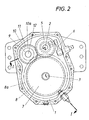
- a front PTO shaft gear 1 which has an input shaft 2 which can be coupled to the tractor drive motor and an output shaft 4 which forms the PTO shaft stub 3.
- a sliding wheel 5, which serves as a drive wheel is seated in a rotationally fixed manner and can be displaced into an exemption and two switching positions via a switching device 6.
- the output shaft 4 receives two output gears 7, 8 arranged directly next to one another, which can be of different dimensions and, on the one hand, can be directly connected to the sliding wheel 5 via a double wheel 9.
- the double wheel 9 is loosely supported by its two individual wheels 10, 11 on an intermediate shaft 12, one wheel 10 of the double wheel 9 constantly meshing with the driven wheel 8 which is farther from the PTO shaft stub 3 and the other wheel 11 of the double wheel 9 overlapping the sliding wheel 5 in one of the Switch positions with the sliding wheel 5 comes into engagement. In the other switching position, the sliding wheel 5 engages directly in the driven wheel 7 adjacent to the PTO stub 3, the release of the sliding wheel 5 being located between these two switching positions.
- a further idler gear 13 can be mounted on the double gear 9, which in turn meshes constantly with the driven gear 7 and instead of this driven gear 7 is assigned to the sliding gear 5 in the one switching position, so that the sliding gear 5 with none of the Output wheels 7, 8 meshes more directly, but in one switching position with one wheel 11 of the double wheel 9 and in the other switching position with the idler gear 13, whereby two different speed levels can be switched while the direction of rotation of the output shaft 4 remains the same.
- the front PTO transmission 1 can be offered in different design variants, the components remaining essentially the same except for the gears to be dimensioned differently.
- the PTO shaft 1 is simply designed for a PTO shaft that rotates clockwise in the direction of travel and can be driven at a specific speed, preferably 1000 rpm.
- the gearbox only needs to be equipped with the sliding wheel 5 itself and a single driven wheel 7, the sliding wheel and driven wheel giving the desired reduction and the sliding wheel 5 being switchable from one switch position to the release for the complete mechanical separation of the drive train.
- the PTO shaft stub 3 can be driven at a speed, preferably 1000 rpm, clockwise or counterclockwise, for which purpose the PTO shaft 1 comprises two drive wheels 7, 8 of the same size and a corresponding double wheel 9 in addition to the sliding wheel 5.
- the direction of rotation of the PTO shaft stub 3 is changed by switching the sliding wheel 5 from one to the other switching position at a constant speed.
- driven gears 7, 8a and a double gear 9a matched to the sliding wheel 5 so that in one shift position the PTO stub 3 rotates clockwise at a higher speed, for example 1000 rpm, and in the other shift position counterclockwise at lower speed, for example 540 rpm, is driven.
- the PTO transmission 1 illustrated in FIG. 7 has a PTO stub 3 which only rotates to the left and accordingly has only one output gear 8a which meshes with the wheel 10a of the double gear 9a, the desired speed, for example 1000 rpm or 540 rpm, being provided by suitable dimensioning of the wheels. min, can be selected.
- the sliding wheel 5 can only be brought into a switching position in which it meshes with the free wheel 11 of the double wheel 9a.
- Fig. 8 shows a PTO transmission 1, which has a left-rotating PTO stub 3 which can be driven at two different speeds, preferably 1000 rpm and 540 rpm, for which purpose it also has the sliding wheel 5, the two driven wheels 7, 8a and the double wheel 9a the idler gear 13 mounted on the double gear 9a.
- the two differently sized output gears 7, 8a mesh on the one hand with the one wheel 10a of the double wheel 9a, on the other hand with the idler gear 13 and the sliding wheel 5 can be in its two switching positions once with the idler gear 13, the other time with the free gear 11 of the dual gear 9 engage so that there is a left turn of the PTO stub at a speed determined by the switching positions.
- the release of the sliding wheel 5 entails a complete mechanical separation of the PTO stub 3 from the drive motor.
- the PTO transmission according to the invention is characterized by its wide range of applications and can be adapted to the most varied of requirements in the most economical manner. This results in a relatively low manufacturing effort and, above all, a very short overall length.
Landscapes
- Engineering & Computer Science (AREA)
- General Engineering & Computer Science (AREA)
- Mechanical Engineering (AREA)
- Chemical & Material Sciences (AREA)
- Combustion & Propulsion (AREA)
- Transportation (AREA)
- Arrangement And Driving Of Transmission Devices (AREA)
Applications Claiming Priority (2)
| Application Number | Priority Date | Filing Date | Title |
|---|---|---|---|
| AT156388A AT399316B (de) | 1988-06-16 | 1988-06-16 | Zapfwellengetriebe, insbesondere für die frontzapfwelle von ackerschleppern od. dgl. |
| AT1563/88 | 1988-06-16 |
Publications (2)
| Publication Number | Publication Date |
|---|---|
| EP0357584A1 true EP0357584A1 (fr) | 1990-03-07 |
| EP0357584B1 EP0357584B1 (fr) | 1992-04-15 |
Family
ID=3516110
Family Applications (1)
| Application Number | Title | Priority Date | Filing Date |
|---|---|---|---|
| EP19890890165 Expired - Lifetime EP0357584B1 (fr) | 1988-06-16 | 1989-06-15 | Engrenage de prise de force particulièrement pour un arbre de prise de force avant de tracteur agricole |
Country Status (3)
| Country | Link |
|---|---|
| EP (1) | EP0357584B1 (fr) |
| AT (1) | AT399316B (fr) |
| DE (1) | DE58901155D1 (fr) |
Cited By (10)
| Publication number | Priority date | Publication date | Assignee | Title |
|---|---|---|---|---|
| RU2137620C1 (ru) * | 1997-03-27 | 1999-09-20 | Общество с ограниченной ответственностью "КОМ" | Коробка отбора мощности |
| RU2348846C1 (ru) * | 2007-06-08 | 2009-03-10 | Государственное учреждение Всероссийский научно-исследовательский институт птицеперерабатывающей промышленности (ГУ ВНИИПП) | Кулачковый пространственный механизм |
| RU2381915C2 (ru) * | 2004-06-18 | 2010-02-20 | СКАНИА СВ АБ (пабл) | Способ и система для получения определенного передаточного отношения, а также держатель опоры |
| CN102927218A (zh) * | 2012-11-02 | 2013-02-13 | 无锡华联科技集团有限公司 | 管子倒角机传动箱机构 |
| CN102943848A (zh) * | 2012-11-12 | 2013-02-27 | 江苏省无锡探矿机械总厂有限公司 | 回转器变速机构 |
| CN103195882A (zh) * | 2013-04-16 | 2013-07-10 | 李章民 | 一种给量变速箱 |
| CN103195883A (zh) * | 2013-04-23 | 2013-07-10 | 山东常林农业装备股份有限公司 | 一种四驱后轮转向花生收获机用直接安装在变速箱后部的分动箱总成 |
| CN103291857A (zh) * | 2013-06-13 | 2013-09-11 | 广西宜州玉柴农业装备有限公司 | 小型拖拉机变速箱 |
| CN103486205A (zh) * | 2013-09-19 | 2014-01-01 | 封新初 | 一种新颖农机动力变速箱总成 |
| CN105345671A (zh) * | 2015-12-07 | 2016-02-24 | 重庆大江工业有限责任公司 | 一种地面抛丸机传动系统 |
Families Citing this family (3)
| Publication number | Priority date | Publication date | Assignee | Title |
|---|---|---|---|---|
| DE4244321A1 (de) * | 1992-12-28 | 1994-06-30 | Kloeckner Humboldt Deutz Ag | Zapfwellenanordnung für einen Traktor |
| DE102008002590B4 (de) * | 2008-06-24 | 2021-02-18 | Zf Friedrichshafen Ag | Getriebe mit einem Nebenabtrieb |
| DE102010050073A1 (de) | 2009-11-16 | 2011-05-19 | Schaeffler Technologies Gmbh & Co. Kg | Mehrstufiges Getriebe |
Citations (3)
| Publication number | Priority date | Publication date | Assignee | Title |
|---|---|---|---|---|
| GB582860A (en) * | 1944-08-07 | 1946-11-29 | Austin Motor Co Ltd | Improvements in means for taking off power from the drive transmission of motor vehicles |
| US2636390A (en) * | 1949-05-06 | 1953-04-28 | Robert W Wagner | Power take-off |
| DE937868C (de) * | 1953-06-06 | 1956-01-19 | Zahnradfabrik Friedrichshafen | Fahrzeugtriebwerk fuer Ackerschlepper |
Family Cites Families (2)
| Publication number | Priority date | Publication date | Assignee | Title |
|---|---|---|---|---|
| JPS569921U (fr) * | 1979-07-02 | 1981-01-28 | ||
| AT372046B (de) * | 1980-02-29 | 1983-08-25 | Steyr Daimler Puch Ag | Nebenabtrieb fuer kraftfahrzeug-wechselgetriebe |
-
1988
- 1988-06-16 AT AT156388A patent/AT399316B/de not_active IP Right Cessation
-
1989
- 1989-06-15 DE DE8989890165T patent/DE58901155D1/de not_active Expired - Fee Related
- 1989-06-15 EP EP19890890165 patent/EP0357584B1/fr not_active Expired - Lifetime
Patent Citations (3)
| Publication number | Priority date | Publication date | Assignee | Title |
|---|---|---|---|---|
| GB582860A (en) * | 1944-08-07 | 1946-11-29 | Austin Motor Co Ltd | Improvements in means for taking off power from the drive transmission of motor vehicles |
| US2636390A (en) * | 1949-05-06 | 1953-04-28 | Robert W Wagner | Power take-off |
| DE937868C (de) * | 1953-06-06 | 1956-01-19 | Zahnradfabrik Friedrichshafen | Fahrzeugtriebwerk fuer Ackerschlepper |
Cited By (14)
| Publication number | Priority date | Publication date | Assignee | Title |
|---|---|---|---|---|
| RU2137620C1 (ru) * | 1997-03-27 | 1999-09-20 | Общество с ограниченной ответственностью "КОМ" | Коробка отбора мощности |
| RU2381915C2 (ru) * | 2004-06-18 | 2010-02-20 | СКАНИА СВ АБ (пабл) | Способ и система для получения определенного передаточного отношения, а также держатель опоры |
| RU2348846C1 (ru) * | 2007-06-08 | 2009-03-10 | Государственное учреждение Всероссийский научно-исследовательский институт птицеперерабатывающей промышленности (ГУ ВНИИПП) | Кулачковый пространственный механизм |
| CN102927218B (zh) * | 2012-11-02 | 2015-03-18 | 无锡华联科技集团有限公司 | 管子倒角机传动箱机构 |
| CN102927218A (zh) * | 2012-11-02 | 2013-02-13 | 无锡华联科技集团有限公司 | 管子倒角机传动箱机构 |
| CN102943848A (zh) * | 2012-11-12 | 2013-02-27 | 江苏省无锡探矿机械总厂有限公司 | 回转器变速机构 |
| CN103195882A (zh) * | 2013-04-16 | 2013-07-10 | 李章民 | 一种给量变速箱 |
| CN103195882B (zh) * | 2013-04-16 | 2016-02-03 | 李章民 | 一种给量变速箱 |
| CN103195883A (zh) * | 2013-04-23 | 2013-07-10 | 山东常林农业装备股份有限公司 | 一种四驱后轮转向花生收获机用直接安装在变速箱后部的分动箱总成 |
| CN103195883B (zh) * | 2013-04-23 | 2015-11-25 | 山东常林农业装备股份有限公司 | 一种四驱后轮转向花生收获机用直接安装在变速箱后部的分动箱总成 |
| CN103291857A (zh) * | 2013-06-13 | 2013-09-11 | 广西宜州玉柴农业装备有限公司 | 小型拖拉机变速箱 |
| CN103291857B (zh) * | 2013-06-13 | 2016-03-23 | 广西宜州玉柴农业装备有限公司 | 小型拖拉机变速箱 |
| CN103486205A (zh) * | 2013-09-19 | 2014-01-01 | 封新初 | 一种新颖农机动力变速箱总成 |
| CN105345671A (zh) * | 2015-12-07 | 2016-02-24 | 重庆大江工业有限责任公司 | 一种地面抛丸机传动系统 |
Also Published As
| Publication number | Publication date |
|---|---|
| ATA156388A (de) | 1994-09-15 |
| DE58901155D1 (de) | 1992-05-21 |
| AT399316B (de) | 1995-04-25 |
| EP0357584B1 (fr) | 1992-04-15 |
Similar Documents
| Publication | Publication Date | Title |
|---|---|---|
| EP2916044B1 (fr) | Système d'engrenage | |
| DE3822330C2 (fr) | ||
| DE69211558T2 (de) | Antriebsrad mit elektromotor, insbesondere für fahrräder, und mit eingebauter gangschaltung | |
| EP0357584B1 (fr) | Engrenage de prise de force particulièrement pour un arbre de prise de force avant de tracteur agricole | |
| DE3639097C2 (fr) | ||
| DE102016216120A1 (de) | Zweistufiger Planetentrieb für ein Verteilergetriebe und Verteilergetriebe | |
| EP0683065A1 (fr) | Boîte de vitesses pour véhicule tout-terrains | |
| EP4384731B1 (fr) | Ensemble train d'engrenages et système d'engrenage de bicyclette | |
| EP0151711A2 (fr) | Agencement pour une transmission | |
| WO1987003661A1 (fr) | Boite de changement a echelonnement multiple de vitesses | |
| EP0560202A1 (fr) | Transmission à vitesses multiples pour véhicules automobiles | |
| DE19624857B4 (de) | Kurzbauendes Sechsganggetriebe | |
| EP0064678B1 (fr) | Ensemble de transmission pour véhicule, en particulier pour véhicule à moteur avec traction avant | |
| DE4238025A1 (de) | Getriebe mit mehreren schaltbaren Gängen | |
| EP0552673A1 (fr) | Boîte de vitesse pour véhicule à moteur | |
| DE4409224A1 (de) | Allradantrieb | |
| AT4607U1 (de) | Verteilergetriebe für kraftfahrzeuge mit geländegang und versetztem abtrieb | |
| DE3445531C2 (fr) | ||
| DE102014225337A1 (de) | Verteilergetriebe | |
| EP1301368B1 (fr) | Boite de vitesses intermediaire pour vehicules automobiles comportant un rapport tout terrain | |
| EP0026853B1 (fr) | Engrenage planétaire, notamment pour véhicules automobiles | |
| EP3211270A1 (fr) | Boîte de vitesses à double embrayage pour véhicules automobiles | |
| DE3326328C2 (de) | Vorrichtung zum Antrieb eines Kraftfahrzeuges für wahlweisen Zweirad- oder Vierrad-Antrieb | |
| DE69730726T2 (de) | Rückwärtsgang-schaltmechanismus in einem querliegenden vorderradgetriebe | |
| DE1455885B2 (de) | Getriebeanordnung fuer kraftfahrzeuge mit mehrachsantrieb |
Legal Events
| Date | Code | Title | Description |
|---|---|---|---|
| PUAI | Public reference made under article 153(3) epc to a published international application that has entered the european phase |
Free format text: ORIGINAL CODE: 0009012 |
|
| 17P | Request for examination filed |
Effective date: 19891011 |
|
| AK | Designated contracting states |
Kind code of ref document: A1 Designated state(s): CH DE FR GB IT LI |
|
| 17Q | First examination report despatched |
Effective date: 19910125 |
|
| GRAA | (expected) grant |
Free format text: ORIGINAL CODE: 0009210 |
|
| ITF | It: translation for a ep patent filed | ||
| AK | Designated contracting states |
Kind code of ref document: B1 Designated state(s): CH DE FR GB IT LI |
|
| REF | Corresponds to: |
Ref document number: 58901155 Country of ref document: DE Date of ref document: 19920521 |
|
| GBT | Gb: translation of ep patent filed (gb section 77(6)(a)/1977) | ||
| ET | Fr: translation filed | ||
| PLBE | No opposition filed within time limit |
Free format text: ORIGINAL CODE: 0009261 |
|
| STAA | Information on the status of an ep patent application or granted ep patent |
Free format text: STATUS: NO OPPOSITION FILED WITHIN TIME LIMIT |
|
| 26N | No opposition filed | ||
| PGFP | Annual fee paid to national office [announced via postgrant information from national office to epo] |
Ref country code: GB Payment date: 19940516 Year of fee payment: 6 Ref country code: CH Payment date: 19940516 Year of fee payment: 6 |
|
| PG25 | Lapsed in a contracting state [announced via postgrant information from national office to epo] |
Ref country code: GB Effective date: 19950615 |
|
| PG25 | Lapsed in a contracting state [announced via postgrant information from national office to epo] |
Ref country code: LI Effective date: 19950630 Ref country code: CH Effective date: 19950630 |
|
| GBPC | Gb: european patent ceased through non-payment of renewal fee |
Effective date: 19950615 |
|
| REG | Reference to a national code |
Ref country code: CH Ref legal event code: PL |
|
| PGFP | Annual fee paid to national office [announced via postgrant information from national office to epo] |
Ref country code: FR Payment date: 19990512 Year of fee payment: 11 |
|
| PGFP | Annual fee paid to national office [announced via postgrant information from national office to epo] |
Ref country code: DE Payment date: 19990525 Year of fee payment: 11 |
|
| PG25 | Lapsed in a contracting state [announced via postgrant information from national office to epo] |
Ref country code: FR Free format text: LAPSE BECAUSE OF NON-PAYMENT OF DUE FEES Effective date: 20010228 |
|
| REG | Reference to a national code |
Ref country code: FR Ref legal event code: ST |
|
| PG25 | Lapsed in a contracting state [announced via postgrant information from national office to epo] |
Ref country code: DE Free format text: LAPSE BECAUSE OF NON-PAYMENT OF DUE FEES Effective date: 20010403 |
|
| PG25 | Lapsed in a contracting state [announced via postgrant information from national office to epo] |
Ref country code: IT Free format text: LAPSE BECAUSE OF NON-PAYMENT OF DUE FEES;WARNING: LAPSES OF ITALIAN PATENTS WITH EFFECTIVE DATE BEFORE 2007 MAY HAVE OCCURRED AT ANY TIME BEFORE 2007. THE CORRECT EFFECTIVE DATE MAY BE DIFFERENT FROM THE ONE RECORDED. Effective date: 20050615 |