EP0357778B1 - Verfahren zur regelung der geschwindigkeit für servomotoren - Google Patents
Verfahren zur regelung der geschwindigkeit für servomotoren Download PDFInfo
- Publication number
- EP0357778B1 EP0357778B1 EP89900306A EP89900306A EP0357778B1 EP 0357778 B1 EP0357778 B1 EP 0357778B1 EP 89900306 A EP89900306 A EP 89900306A EP 89900306 A EP89900306 A EP 89900306A EP 0357778 B1 EP0357778 B1 EP 0357778B1
- Authority
- EP
- European Patent Office
- Prior art keywords
- acceleration
- speed
- machine
- deceleration
- sampling
- Prior art date
- Legal status (The legal status is an assumption and is not a legal conclusion. Google has not performed a legal analysis and makes no representation as to the accuracy of the status listed.)
- Expired - Lifetime
Links
Images


Classifications
-
- G—PHYSICS
- G05—CONTROLLING; REGULATING
- G05B—CONTROL OR REGULATING SYSTEMS IN GENERAL; FUNCTIONAL ELEMENTS OF SUCH SYSTEMS; MONITORING OR TESTING ARRANGEMENTS FOR SUCH SYSTEMS OR ELEMENTS
- G05B19/00—Program-control systems
- G05B19/02—Program-control systems electric
- G05B19/18—Numerical control [NC], i.e. automatically operating machines, in particular machine tools, e.g. in a manufacturing environment, so as to execute positioning, movement or co-ordinated operations by means of program data in numerical form
- G05B19/416—Numerical control [NC], i.e. automatically operating machines, in particular machine tools, e.g. in a manufacturing environment, so as to execute positioning, movement or co-ordinated operations by means of program data in numerical form characterised by control of velocity, acceleration or deceleration
-
- G—PHYSICS
- G05—CONTROLLING; REGULATING
- G05B—CONTROL OR REGULATING SYSTEMS IN GENERAL; FUNCTIONAL ELEMENTS OF SUCH SYSTEMS; MONITORING OR TESTING ARRANGEMENTS FOR SUCH SYSTEMS OR ELEMENTS
- G05B2219/00—Program-control systems
- G05B2219/30—Nc systems
- G05B2219/42—Servomotor, servo controller kind till VSS
- G05B2219/42256—Sampling the signal
-
- G—PHYSICS
- G05—CONTROLLING; REGULATING
- G05B—CONTROL OR REGULATING SYSTEMS IN GENERAL; FUNCTIONAL ELEMENTS OF SUCH SYSTEMS; MONITORING OR TESTING ARRANGEMENTS FOR SUCH SYSTEMS OR ELEMENTS
- G05B2219/00—Program-control systems
- G05B2219/30—Nc systems
- G05B2219/43—Speed, acceleration, deceleration control ADC
- G05B2219/43013—Ramp signal from division of sum of registers
-
- G—PHYSICS
- G05—CONTROLLING; REGULATING
- G05B—CONTROL OR REGULATING SYSTEMS IN GENERAL; FUNCTIONAL ELEMENTS OF SUCH SYSTEMS; MONITORING OR TESTING ARRANGEMENTS FOR SUCH SYSTEMS OR ELEMENTS
- G05B2219/00—Program-control systems
- G05B2219/30—Nc systems
- G05B2219/43—Speed, acceleration, deceleration control ADC
- G05B2219/43062—Maximum acceleration, limit
Definitions
- the present invention relates to a method for an acceleration and deceleration control of servomotors.
- a required number of servomotors mounted thereon are employed to drive operating sections of the respective machine along or around corresponding control axes.
- acceleration/deceleration control of the servomotor is automatically performed to prevent the machine from undergoing overload or vibration.
- a movement command value per unit time i.e., a commanded speed Pa
- a computer or an interpolation and distribution control unit (not shown).
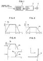
- an acceleration/deceleration control unit 1 receiving a first pulse train which corresponds to the commanded speed Pa after interpolation (indicated by the dashed line)
- the time constant T with which the acceleration/deceleration control is carried out is preset to such a value that the machine is operated at the maximum allowable acceleration when the commanded speed Pa assumes its maximum value.
- the time constant is invariable regardless of whether the commanded speed Pa is large (FIG. 2) or small (FIG. 3).
- the machine is operated at the maximum allowable acceleration only when the maximum commanded speed is generated, and in other cases, the acceleration at which the machine is operated becomes smaller with a decrease of the commanded speed.
- the maximum operating capability of the machine cannot be used and the operating time required (cycle time) increases.
- an operating section of a machine such as a tool provided in a machine tool, work point of a robot, etc.
- its actual movement path is rounded and displaced from the commanded movement path.
- an X-axis direction movement command of the speed Pa and a Y-axis movement command of the speed Pa are applied in the mentioned order, as indicated by the dashed lines in FIG.
- the acceleration/deceleration control unit 1 delivers a commanded speed Pb for the X axis and that for the Y axis in sequence, as indicated by the solid lines in FIG. 4.
- the machine operating section is accelerated in the Y-axis direction while it is decelerated in the X-axis direction, and accordingly its movement path is rounded, as indicated by the solid line in FIG. 5.
- the radius of the round becomes greater as the time constant T increases.
- a known acceleration/deceleration control method is disclosed in EP-A-0,139,010.
- a servomotor commanded speed is sampled at predetermined intervals, and acceleration/deceleration control is carried out in accordance with the sampled commanded speed over an acceleration/deceleration period. Change in velocity is decreased, and vibrations are prevented, by connecting a low-pass filter at the output side of an acceleration/deceleration control system.
- EP-A-0,191,103 discloses a method of controlling a multi-joint robot so that the shortest acceleration time and deceleration time can be attained with all of the torques applied to motors and decelerators driving first and second arms of the robot within tolerance limits.
- a method according to the present invention is capable of utilising at all times the maximum operating capability of various machines equipped with servomotors. It is also capable of moving operating sections of various machines equipped with servomotors, exactly along a commanded path.
- each of at least two servomotors mounted to a machine are controlled with the time constant determined by dividing the speed command value by the maximum allowable acceleration of the machine, it is possible to make the best use of the operating capability of various machines such as robots, machine tools and the like, and thus the required operating time of the machines can be shortened. Furthermore, the curvature of the movement path of the machine operating section such as a work point of a robot, tool of a machine tool, etc., which is created when the operating section is moved along a corner, can be reduced, whereby the machine operating section can be controlled to move accurately along the commanded path.
- a machine such as a robot, NC machine tool or the like (not shown) to which a method for acceleration and deceleration control of servomotors according to the present invention is applied, comprises a control system (not shown), which consists of a microcomputer, for example.
- the control system is constructed in a manner similar to that of a conventional one.
- the control system of the present invention is so arranged that its memory is stored with a maximum allowable acceleration Am for the machine, preferably, for a respective control axis associated with each operating section of the machine, the maximum allowable acceleration being determined in dependence on the type of the machine, as distinct from the conventional control system in which a time constant T for acceleration/deceleration control is stored in its memory.
- a central processing unit of the microcomputer having similar functions to those of the acceleration/deceleration control unit 1 of FIG. 1, reads out a speed command from a machine operation control program (Step S1 in FIG. 8).
- the value F may be divided by the product of the values Am and ⁇ .
- the central processing unit executes an acceleration/deceleration process shown in FIG. 9, in each commanded speed sampling period ⁇ .
- the acceleration/deceleration process will be described for one of the control axes of the machine corresponding to the speed command.
- the central processing unit adds together the commanded speed Pa for the control axis concerned, obtained by an interpolation as conventionally known, and values R1 to Rn-1 sampled at the previous sampling to an n th sampling preceding the current one for this control axis, respectively, and stored in the first to (n-1)th registers of the central processing unit at the current sampling, respectively, and divides the sum (Pa + R1 + R2 + ...
- Step S11 The commanded speed Pb is sent to a servo-circuit (not shown) associated with the above control axis and corresponding to the servo control unit 2 in FIG. 1 (Step S12).
- the central processing unit transfers the values Rn-2 to R1, stored respectively in the (n-2)th through the first registers, to the (n-1)th through the second registers, respectively (Step S13), and stores the value Pa in the first register (Step S14), thereby completing the acceleration/deceleration process of the current commanded speed sampling for one control axis.
- step S11 will now be described in more detail.
- the commanded speed Pa for one of the control axes corresponding to the above speed command is 100 and the number of times of sampling, n , is 5, for example.
- the command speeds Pb for the third to fifth sampling periods are 60, 80 and 100, respectively.
- the commanded speed Pb after acceleration/deceleration process is maintained at 100 as far as the commanded speed Pa is 100, and in which case the servomotor corresponding to the servomotor 3 of FIG. 1 is operated at a constant speed.
- the command speeds Pb for the subsequent four sampling periods are 60, 40, 20 and 0, respectively, so that a decelerated operation is carried out. Thereafter, the commanded speed Pb is maintained at "0" as far as the commanded speed Pa is "0".
- linear acceleration/deceleration control is described, but the present invention is not limited to this type control alone.
- exponential acceleration and deceleration control may be used.
Landscapes
- Engineering & Computer Science (AREA)
- Human Computer Interaction (AREA)
- Manufacturing & Machinery (AREA)
- Physics & Mathematics (AREA)
- General Physics & Mathematics (AREA)
- Automation & Control Theory (AREA)
- Numerical Control (AREA)
- Manipulator (AREA)
- Control Of Electric Motors In General (AREA)
Claims (4)
- Verfahren zur Beschleunigungs- und Verzögerungs-Regelung von Servomotoren (3), das Schritte umfaßt zum(a) Abtasten einer Soll-Geschwindigkeit (Pa) für zumindest einen Servomotor, der an einer Maschine montiert ist, in vorbestimmten Intervallen (τ) und(b) Ausführen einer Beschleunigungs/Verzögerungs-Regelung in Übereinstimmung mit der abgetasteten Soll-Geschwindigkeit (Pa) über eine Beschleunigungs/Verzögerungs-Periode hinweg,dadurch gekennzeichnet, daß
die Beschleunigungs/Verzögerungs-Periode gemäß Schritt (b) als eine Zeitkonstante (T) bestimmt ist, über welche hinweg die Beschleunigungs/Verzögerungs-Regelung durch Dividieren eines Werts eines Geschwindigkeitsbefehls (Pa) durch eine zuvor eingestellte maximal zulässige Beschleunigung (Am) der Maschine ausgeführt wird, wenn der Geschwindigkeitsbefehl (Pa) aus einem Programm ausgelesen ist. - Verfahren zur Beschleunigungs- und Verzögerungs-Regelung von Servomotoren (3) nach Anspruch 1, bei dem das Abtasten der Soll-Geschwindigkeit (Pa) in Schritt (a) für zumindest zwei Servomotoren (3) ausgeführt wird.
- Verfahren zur Beschleunigungs- und Verzögerungs-Regelung von Servomotoren (3) nach Anspruch 1 oder 2, bei dem die Maschine zumindest einen Arbeitsabschnitt hat, der in bezug auf zumindest eine Steuerachse getrieben wird, und die maximal zulässige Beschleunigung (Am) eine maximal zulässige Beschleunigung für eine Steuerachse unter den Steuerachsen oder die zumindest eine Steuerachse ist, der die Soll-Geschwindigkeit (Pa) zugeordnet ist, und abgetastet wird.
- Verfahren zur Beschleunigungs- und Verzögerungs-Regelung von Servomotoren (3) nach einem der vorhergehenden Ansprüche, bei dem die Beschleunigungs/Verzögerungs-Regelung in Schritt (b) während der Periode der Zeitkonstanten (T) in Übereinstimmung mit einer Reihe von ansteigenden oder abfallenden Soll-Geschwindigkeitswerten (Pb), die für Abtastzeitpunkte berechnet sind, während der Periode der Zeitkonstanten (T) ausgeführt wird, die in den vorbestimmten Abtastintervallen (τ) auftritt, wobei die Anzahl (n) solcher Abtastzeitpunkte durch Dividieren der Periode der Zeitkonstanten (T) durch das vorbestimmte Abtastintervall (τ) gewonnen wird und jeder Soll-Geschwindigkeitswert (Pb) für einen einzelnen Abtastzeitpunkt während der Periode der Zeitkonstanten (T) durch Dividieren der Summe der abgetasteten Soll-Geschwindigkeiten (Pa) für den augenblicklichen Abtastzeitpunkt und vorhergehende (n-1) Abtastzeitpunkte durch die Gesamtanzahl (n) von Abtastzeitpunkten in der Periode der Zeitkonstanten (T) gewonnen wird.
Applications Claiming Priority (3)
| Application Number | Priority Date | Filing Date | Title |
|---|---|---|---|
| JP62321496A JPH01164280A (ja) | 1987-12-21 | 1987-12-21 | 加減速制御方式 |
| JP321496/87 | 1987-12-21 | ||
| PCT/JP1988/001241 WO1989006066A1 (fr) | 1987-12-21 | 1988-12-09 | Procede de commande de vitesse pour servomoteur |
Publications (3)
| Publication Number | Publication Date |
|---|---|
| EP0357778A1 EP0357778A1 (de) | 1990-03-14 |
| EP0357778A4 EP0357778A4 (en) | 1992-03-04 |
| EP0357778B1 true EP0357778B1 (de) | 1995-07-26 |
Family
ID=18133205
Family Applications (1)
| Application Number | Title | Priority Date | Filing Date |
|---|---|---|---|
| EP89900306A Expired - Lifetime EP0357778B1 (de) | 1987-12-21 | 1988-12-09 | Verfahren zur regelung der geschwindigkeit für servomotoren |
Country Status (5)
| Country | Link |
|---|---|
| US (1) | US5004968A (de) |
| EP (1) | EP0357778B1 (de) |
| JP (1) | JPH01164280A (de) |
| DE (1) | DE3854233T2 (de) |
| WO (1) | WO1989006066A1 (de) |
Families Citing this family (17)
| Publication number | Priority date | Publication date | Assignee | Title |
|---|---|---|---|---|
| JP2935713B2 (ja) * | 1989-08-22 | 1999-08-16 | ファナック株式会社 | 数値制御装置 |
| EP0477412A1 (de) * | 1990-09-27 | 1992-04-01 | Siemens Aktiengesellschaft | Verfahren zur Filterung digitaler Signale |
| US5396160A (en) * | 1991-03-11 | 1995-03-07 | General Motors Corporation | Method of real-time machine path planning from a math model |
| JP3083870B2 (ja) * | 1991-05-10 | 2000-09-04 | ファナック株式会社 | 数値制御装置 |
| US5254920A (en) * | 1991-06-14 | 1993-10-19 | Western Digital (Singapore) Pte. Ltd. | Seek system for sector servo disk drive |
| JPH05324046A (ja) * | 1992-05-18 | 1993-12-07 | Mitsubishi Electric Corp | 多系統数値制御方法及びその装置 |
| JPH07200031A (ja) * | 1993-12-28 | 1995-08-04 | Sony Corp | 数値制御方法と数値制御装置 |
| JPH08137524A (ja) * | 1994-11-09 | 1996-05-31 | Fanuc Ltd | ロボットの軌道計画時における時定数の設定方法 |
| US5740327A (en) * | 1994-12-27 | 1998-04-14 | Nec Corporation | Method of and apparatus for robot tip trajectory control |
| DE69605640T2 (de) * | 1995-08-23 | 2000-04-13 | Fanuc Ltd., Yamanashi | Numerische verschnellungs-/verzogerungs steuergerat und verfahren |
| US6289256B1 (en) * | 1997-01-16 | 2001-09-11 | Matsushita Electric Industrial Co., Ltd. | Method and apparatus for mounting parts |
| JP5499865B2 (ja) * | 2010-04-19 | 2014-05-21 | パナソニック株式会社 | 多関節型ロボットの速度指令プロファイルの生成方法 |
| CN102236338B (zh) * | 2010-04-22 | 2013-11-13 | 上海微电子装备有限公司 | 四阶定值发生器的实现方法 |
| US8700190B2 (en) | 2011-08-05 | 2014-04-15 | Mitsubishi Electric Research Labs. | Method for generating trajectories for motor controlled actuators |
| JP5838681B2 (ja) * | 2011-09-16 | 2016-01-06 | いすゞ自動車株式会社 | アクチュエータの制御方法及びアクチュエータの制御装置 |
| DE102014207072A1 (de) * | 2014-04-11 | 2015-10-15 | Kuka Roboter Gmbh | Verfahren zum Betreiben einer Bremse und zugehörige Maschine, insbesondere Roboter |
| CN110647120B (zh) * | 2019-09-26 | 2021-01-01 | 北京机电工程研究所 | 一种适用于极端应用条件的运动控制方法 |
Citations (1)
| Publication number | Priority date | Publication date | Assignee | Title |
|---|---|---|---|---|
| JPS619180A (ja) * | 1984-06-20 | 1986-01-16 | Matsushita Electric Ind Co Ltd | サ−ボモ−タの加減速制御方法 |
Family Cites Families (15)
| Publication number | Priority date | Publication date | Assignee | Title |
|---|---|---|---|---|
| DE2643148A1 (de) * | 1976-09-24 | 1978-03-30 | Siemens Ag | Steuereinrichtung bei einer rechnergefuehrten steuerung einer numerisch gesteuerten werkzeugmaschine |
| JPS6047836B2 (ja) * | 1977-12-07 | 1985-10-23 | 沖電気工業株式会社 | 位置決め制御方法 |
| DE3277245D1 (en) * | 1981-03-04 | 1987-10-15 | Hitachi Ltd | Method for controlling angular position and apparatus therefor |
| JPS5835607A (ja) * | 1981-08-27 | 1983-03-02 | Fanuc Ltd | 数値制御装置 |
| JPS58151885A (ja) * | 1982-03-03 | 1983-09-09 | Hitachi Ltd | モ−タの位置制御方法 |
| JPS58172709A (ja) * | 1982-04-02 | 1983-10-11 | Toko Inc | 自動加減速制御回路 |
| JPS58211211A (ja) * | 1982-06-01 | 1983-12-08 | Fanuc Ltd | 数値制御方式 |
| FR2530173B1 (fr) * | 1982-07-14 | 1987-08-14 | Kuka Schweissanlagen & Roboter | Procede et montage pour freiner une partie de machine et pour l'arreter |
| JPS5962909A (ja) * | 1982-10-01 | 1984-04-10 | Fanuc Ltd | 加減速装置 |
| JPS59168513A (ja) * | 1983-03-16 | 1984-09-22 | Fanuc Ltd | 加減速制御方式 |
| JPS6020209A (ja) * | 1983-07-14 | 1985-02-01 | Matsushita Electric Ind Co Ltd | ロボツトの補間制御方法 |
| JPH0799486B2 (ja) * | 1984-04-27 | 1995-10-25 | 松下電器産業株式会社 | 角加速度制御方法 |
| JPS6118009A (ja) * | 1984-07-04 | 1986-01-25 | Fanuc Ltd | 加減速制御方式 |
| US4815007A (en) * | 1984-12-20 | 1989-03-21 | Seiko Epson Corporation | Apparatus for controlling a robot |
| JPS61157909A (ja) * | 1984-12-29 | 1986-07-17 | Fanuc Ltd | ロボツトの経路誤差補正方式 |
-
1987
- 1987-12-21 JP JP62321496A patent/JPH01164280A/ja active Pending
-
1988
- 1988-12-09 US US07/381,396 patent/US5004968A/en not_active Expired - Lifetime
- 1988-12-09 DE DE3854233T patent/DE3854233T2/de not_active Expired - Fee Related
- 1988-12-09 WO PCT/JP1988/001241 patent/WO1989006066A1/ja not_active Ceased
- 1988-12-09 EP EP89900306A patent/EP0357778B1/de not_active Expired - Lifetime
Patent Citations (1)
| Publication number | Priority date | Publication date | Assignee | Title |
|---|---|---|---|---|
| JPS619180A (ja) * | 1984-06-20 | 1986-01-16 | Matsushita Electric Ind Co Ltd | サ−ボモ−タの加減速制御方法 |
Also Published As
| Publication number | Publication date |
|---|---|
| EP0357778A4 (en) | 1992-03-04 |
| DE3854233T2 (de) | 1995-12-14 |
| EP0357778A1 (de) | 1990-03-14 |
| WO1989006066A1 (fr) | 1989-06-29 |
| US5004968A (en) | 1991-04-02 |
| DE3854233D1 (de) | 1995-08-31 |
| JPH01164280A (ja) | 1989-06-28 |
Similar Documents
| Publication | Publication Date | Title |
|---|---|---|
| EP0357778B1 (de) | Verfahren zur regelung der geschwindigkeit für servomotoren | |
| EP0187864B1 (de) | Regelsystem für beschleunigung-verlangsamung | |
| EP0207997B1 (de) | Fehlerkorrektur im wege eines roboters | |
| EP0417312B1 (de) | Vorrichtung zur offenen steuerung für einen servomotor | |
| EP0378708A1 (de) | Vorrichtung zur regelung der beschleunigung und verzögerung für servoregelung | |
| KR880001647B1 (ko) | 로보트 제어장치 | |
| EP0299080B1 (de) | Geschwindigkeitsregelvorrichtung in einem servolenksystem | |
| KR910002446B1 (ko) | 속도 제어장치 | |
| US5986422A (en) | Control mode changing over method for servo control system | |
| US5218281A (en) | Acceleration/deceleration control method for a numerical control device | |
| US5708342A (en) | Method of controlling acceleration/deceleration time constants for robot | |
| US5371452A (en) | Adjustable time constant control and method system for a servomotor | |
| KR910002317B1 (ko) | 수치제어장치 | |
| JPS63318240A (ja) | 加減速制御装置 | |
| US5473542A (en) | Method for a time-optimal, true-to-path braking of axle drives of numerically controlled machines | |
| JPH07210225A (ja) | 数値制御装置 | |
| KR970009980A (ko) | 공작 기계의 작업 영역 제어방법 | |
| JP3242190B2 (ja) | 数値制御装置 | |
| WO1989001388A1 (en) | Axis switching device | |
| JPH11194813A (ja) | 産業用機械の動作指令作成方法 | |
| JP3188396B2 (ja) | 数値制御における送り速度制御方法および装置 | |
| JP2694638B2 (ja) | 数値制御装置 | |
| JP2687119B2 (ja) | 数値制御装置 | |
| JP2779797B2 (ja) | 数値制御装置 | |
| EP0362393A1 (de) | Gerät zur pulsinterpolation von hoher genauigkeit |
Legal Events
| Date | Code | Title | Description |
|---|---|---|---|
| PUAI | Public reference made under article 153(3) epc to a published international application that has entered the european phase |
Free format text: ORIGINAL CODE: 0009012 |
|
| 17P | Request for examination filed |
Effective date: 19890725 |
|
| AK | Designated contracting states |
Kind code of ref document: A1 Designated state(s): DE FR GB |
|
| RIN1 | Information on inventor provided before grant (corrected) |
Inventor name: HARA, RYUICHI, ROOM 7-206, FANUC MANSHONHARIMOMI Inventor name: MIZUNO, TORU, ROOM 901 |
|
| A4 | Supplementary search report drawn up and despatched |
Effective date: 19920116 |
|
| AK | Designated contracting states |
Kind code of ref document: A4 Designated state(s): DE FR GB |
|
| 17Q | First examination report despatched |
Effective date: 19930908 |
|
| GRAA | (expected) grant |
Free format text: ORIGINAL CODE: 0009210 |
|
| AK | Designated contracting states |
Kind code of ref document: B1 Designated state(s): DE FR GB |
|
| PG25 | Lapsed in a contracting state [announced via postgrant information from national office to epo] |
Ref country code: FR Effective date: 19950726 |
|
| REF | Corresponds to: |
Ref document number: 3854233 Country of ref document: DE Date of ref document: 19950831 |
|
| PG25 | Lapsed in a contracting state [announced via postgrant information from national office to epo] |
Ref country code: GB Effective date: 19951209 |
|
| EN | Fr: translation not filed | ||
| PLBE | No opposition filed within time limit |
Free format text: ORIGINAL CODE: 0009261 |
|
| STAA | Information on the status of an ep patent application or granted ep patent |
Free format text: STATUS: NO OPPOSITION FILED WITHIN TIME LIMIT |
|
| 26N | No opposition filed | ||
| GBPC | Gb: european patent ceased through non-payment of renewal fee |
Effective date: 19951209 |
|
| PGFP | Annual fee paid to national office [announced via postgrant information from national office to epo] |
Ref country code: DE Payment date: 20051202 Year of fee payment: 18 |
|
| PG25 | Lapsed in a contracting state [announced via postgrant information from national office to epo] |
Ref country code: DE Free format text: LAPSE BECAUSE OF NON-PAYMENT OF DUE FEES Effective date: 20070703 |