EP0357782A1 - Dispositif de commande pour compresseurs a capacite variable - Google Patents
Dispositif de commande pour compresseurs a capacite variable Download PDFInfo
- Publication number
- EP0357782A1 EP0357782A1 EP89901314A EP89901314A EP0357782A1 EP 0357782 A1 EP0357782 A1 EP 0357782A1 EP 89901314 A EP89901314 A EP 89901314A EP 89901314 A EP89901314 A EP 89901314A EP 0357782 A1 EP0357782 A1 EP 0357782A1
- Authority
- EP
- European Patent Office
- Prior art keywords
- pressure
- chamber
- control
- valve
- driving shaft
- Prior art date
- Legal status (The legal status is an assumption and is not a legal conclusion. Google has not performed a legal analysis and makes no representation as to the accuracy of the status listed.)
- Granted
Links
Images

Classifications
-
- F—MECHANICAL ENGINEERING; LIGHTING; HEATING; WEAPONS; BLASTING
- F04—POSITIVE - DISPLACEMENT MACHINES FOR LIQUIDS; PUMPS FOR LIQUIDS OR ELASTIC FLUIDS
- F04B—POSITIVE-DISPLACEMENT MACHINES FOR LIQUIDS; PUMPS
- F04B27/00—Multi-cylinder pumps specially adapted for elastic fluids and characterised by number or arrangement of cylinders
- F04B27/08—Multi-cylinder pumps specially adapted for elastic fluids and characterised by number or arrangement of cylinders having cylinders coaxial with, or parallel or inclined to, main shaft axis
- F04B27/14—Control
- F04B27/16—Control of pumps with stationary cylinders
- F04B27/18—Control of pumps with stationary cylinders by varying the relative positions of a swash plate and a cylinder block
- F04B27/1804—Controlled by crankcase pressure
-
- F—MECHANICAL ENGINEERING; LIGHTING; HEATING; WEAPONS; BLASTING
- F04—POSITIVE - DISPLACEMENT MACHINES FOR LIQUIDS; PUMPS FOR LIQUIDS OR ELASTIC FLUIDS
- F04B—POSITIVE-DISPLACEMENT MACHINES FOR LIQUIDS; PUMPS
- F04B27/00—Multi-cylinder pumps specially adapted for elastic fluids and characterised by number or arrangement of cylinders
- F04B27/08—Multi-cylinder pumps specially adapted for elastic fluids and characterised by number or arrangement of cylinders having cylinders coaxial with, or parallel or inclined to, main shaft axis
- F04B27/14—Control
- F04B27/16—Control of pumps with stationary cylinders
- F04B27/18—Control of pumps with stationary cylinders by varying the relative positions of a swash plate and a cylinder block
- F04B27/1804—Controlled by crankcase pressure
- F04B2027/1809—Controlled pressure
-
- F—MECHANICAL ENGINEERING; LIGHTING; HEATING; WEAPONS; BLASTING
- F04—POSITIVE - DISPLACEMENT MACHINES FOR LIQUIDS; PUMPS FOR LIQUIDS OR ELASTIC FLUIDS
- F04B—POSITIVE-DISPLACEMENT MACHINES FOR LIQUIDS; PUMPS
- F04B27/00—Multi-cylinder pumps specially adapted for elastic fluids and characterised by number or arrangement of cylinders
- F04B27/08—Multi-cylinder pumps specially adapted for elastic fluids and characterised by number or arrangement of cylinders having cylinders coaxial with, or parallel or inclined to, main shaft axis
- F04B27/14—Control
- F04B27/16—Control of pumps with stationary cylinders
- F04B27/18—Control of pumps with stationary cylinders by varying the relative positions of a swash plate and a cylinder block
- F04B27/1804—Controlled by crankcase pressure
- F04B2027/1822—Valve-controlled fluid connection
- F04B2027/1827—Valve-controlled fluid connection between crankcase and discharge chamber
-
- F—MECHANICAL ENGINEERING; LIGHTING; HEATING; WEAPONS; BLASTING
- F04—POSITIVE - DISPLACEMENT MACHINES FOR LIQUIDS; PUMPS FOR LIQUIDS OR ELASTIC FLUIDS
- F04B—POSITIVE-DISPLACEMENT MACHINES FOR LIQUIDS; PUMPS
- F04B27/00—Multi-cylinder pumps specially adapted for elastic fluids and characterised by number or arrangement of cylinders
- F04B27/08—Multi-cylinder pumps specially adapted for elastic fluids and characterised by number or arrangement of cylinders having cylinders coaxial with, or parallel or inclined to, main shaft axis
- F04B27/14—Control
- F04B27/16—Control of pumps with stationary cylinders
- F04B27/18—Control of pumps with stationary cylinders by varying the relative positions of a swash plate and a cylinder block
- F04B27/1804—Controlled by crankcase pressure
- F04B2027/1822—Valve-controlled fluid connection
- F04B2027/1831—Valve-controlled fluid connection between crankcase and suction chamber
-
- F—MECHANICAL ENGINEERING; LIGHTING; HEATING; WEAPONS; BLASTING
- F04—POSITIVE - DISPLACEMENT MACHINES FOR LIQUIDS; PUMPS FOR LIQUIDS OR ELASTIC FLUIDS
- F04B—POSITIVE-DISPLACEMENT MACHINES FOR LIQUIDS; PUMPS
- F04B27/00—Multi-cylinder pumps specially adapted for elastic fluids and characterised by number or arrangement of cylinders
- F04B27/08—Multi-cylinder pumps specially adapted for elastic fluids and characterised by number or arrangement of cylinders having cylinders coaxial with, or parallel or inclined to, main shaft axis
- F04B27/14—Control
- F04B27/16—Control of pumps with stationary cylinders
- F04B27/18—Control of pumps with stationary cylinders by varying the relative positions of a swash plate and a cylinder block
- F04B27/1804—Controlled by crankcase pressure
- F04B2027/184—Valve controlling parameter
- F04B2027/1859—Suction pressure
Definitions
- the present invention relates to a control device for a variable displacement type compressor, said compressor comprising a housing having a plurality of cylinder bores arranged around a rotational driving shaft, an operating piston slidably fitted in each of said cylinder bores, a swashplate connected to said operating piston through a connecting rod, a holder supporting said swashplate, capable of being swung about an axis of a support shaft perpendicular to an axis of the rotational driving shaft and being connected to the rotational driving shaft, and a control piston connected to a sleeve and moved in response to pressure of a control pressure chamber in order to adjust an operating stroke of the operating piston by varying a position of angular displacement around the axis of the support shaft of said holder and said swashplate, a control valve being interposed among an intake chamber, a discharge chamber of said compressor and said control pressure chamber in order to control the discharge amount of the compressor in response to intake pressure.
- the present invention has been accomplished in view of the foregoing. It is an object of the present invention to provide a control device for a variable displacement type compressor which prevents an occurrence of hunting in variation in displacement of a compressor.
- the control valve comprises a first valve mechanism capable of putting the discharge chamber and the control pressure chamber into and out of communication with each other and a second valve mechanism capable of putting the control pressure chamber and the intake chamber into and out of communication with each other, said first valve mechanism being opened when the pressure of the intake chamber is less than a first set pressure and closed when said pressure is equal to or more than the first set pressure, said second valve mechanism being opened when the pressure of the intake chamber is equal to or more than a second set pressure which is smaller than the first set pressure and closed when said pressure is less than the second set pressure.
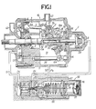
- Figs. land 2 show one embodiment of the present invention, in which Fig. 1 is a longitudinal sectional side view, Fig. 2 is a characteristic curve showing the opening and closing of a control valve, and Fig. 3 is a longitudinal sectional view showing the construction of a conventional control valve.
- a variable displacement type compressor 1 which is applied, for example, to an air conditioner mounted on an automobile, comprises a rotational driving shaft 2, an operating piston 4 slidably fitted in each of a plurality of cylinder bores 3 arranged around the rotational driving shaft 2, a swashplate 6 connected to each of the operating pistons 4 through a connecting rod 5, a holder 7 supporting said swashplate 6 and being arranged swingably around the axis perpendicular to the axis of the rotational driving shaft 2, and a control piston 9 arranged to be moved in response to pressure of a control pressure chamber 8 and connected to said holder 7.
- a housing 10 for the variable displacement type compressor 1 comprises a housing body 11 in the form of a bottomed-cylinder having a block portion lla at one end thereof, a first cover 13 coupled to one end of the housing body 11 through an end place 12, and a second cover 14 coupled to the other end of the housing body 11 to close the open end thereof.
- the rotational driving shaft 2 is arranged to rotatably extend through the first cover 13, the end plate 12 and the block portion lla, the intermediate portion of the rotational driving shaft 2 being supported on the block portion lla through a radial bearing 15, the rotational driving shaft 2 having one end protruded outwardly from the first cover 13.
- the other end of the rotational driving shaft 2 is supported through a radial bearing 17 on a receiving plate 16 received by the second cover 14,. and a thrust bearing 19 is interposed between an integrally fixedly mounted driving plate 18 extended radially outwardly near the other end of the rotational driving shaft 2 and said receiving plate 16.
- a stop ring 20 received by the block portion lla is fixedly mounted on the intermediate portion of the rotational driving shaft 2. Power from a crank shaft of the internal combustion engine (not shown) is transmitted to one end of the rotational driving shaft 2 to thereby rotate the rotational driving shaft 2.
- a plurality of cylinder bores 3 surrounding the rotational driving shaft 2 are bored parallel to the rotational driving shaft 2, and the operating pistons 4 are respectively slidably fitted into the cylinder bores 3.
- One end of each of the cylinder bores 3 is closed by the end plate 12.
- the holder 7 and the swashplate 6 supported by the holder 7 are arranged within an operating chamber 21 formed within the housing 10 between the second cover 14 and the block portion lla.
- the holder 7 comprises a tubular portion 7a encircling the rotational driving shaft 2 and a flange 7b disposed on the end of the tubular portion 7a.
- a radial bearing 22 is disposed between the tubular portion 7a and the swashplate 6, and a thrust bearing 23 is disposed between the flange. 7b and the swashplate 6 so as to support the swashplate 6 on the holder 7.
- a.cylindrical sleeve 24 is axially movably fitted over the rotational driving shaft 2, and the holder 7 is swingably supported by a pair of support shafts 25 protruded outwardly along one diametral line from the outer surface of the sleeve 24, that is, perpendicular to the axis of the rotational driving shaft 2.
- a guide shaft 26 parallel to the rotational driving shaft 2 is mounted--over and between the block portion lla and the second cover 14, and a slidable guide arm 6a in engagement with the guide shaft 26 is provided on the swashplate 6.
- a connecting arm 18a extending toward the holder 7 is provided on a driving plate 18 fixedly mounted on the rotational driving shaft 2, and an engaging pin 28 projected from the holder 7 is engaged with an engaging hole 27 formed in the fore end of the connecting arm 18a.
- the engaging hole 27 is made in the form of an arc to maintain the engaging state with the engaging pin 28 despite the rotation of the holder 7 about the axis of the support shaft 25. Accordingly, the holder 7 and the swashplate 6 are rotated in response to the rotation of the rotational driving shaft 2.
- each of the connecting rods 5 At one end of each of the connecting rods 5 is provided a spherical head 5a, which is engaged with each operating piston 4. At the other end of each connecting rod 5 is also provided a spherical head 5b, which is engaged with the swashplate 6. Accordingly, the operating stroke of the operating piston 4, that is, the discharge amount is determined according to the position of angular displacement of the swashplate 6 around the axis of the support shaft 25.
- An outwardly protruded bottomed-cylindrical cylinder tube portion 29 is projected coaxial with the rotational driving shaft 2 in the central portion of the second cover 14.
- the control piston 9 is slidably fitted into the cylinder tube portion 29, and the control pressure chamber 8 is defined between the control piston 9 and the outer closed end of the cylinder tube portion 29.
- a bottomed sliding hole 30 which is opened to the other end surface of the rotational driving shaft 2 and faces to the cylinder tube portion 29 is coaxially bored in a portion close to the other end of the rotational driving shaft 2, and a rod 31 is slidably fitted into the sliding hole 30.
- a return spring 32 is retained in compression between the closed end of the sliding hole 30 and one end of the rod 31, the rod 31 being urged in a direction of being projected from the other end of the rotational driving shaft 2.
- the other end of the rod 31 is coaxially connected to the control piston 7 so that the rotation of the rod 31 is not transmitted, and a balance spring 33 having a force against the spring 32 to stabilize the movement of the control piston 9 is encased in the control pressure chamber 8.
- a guide hole 34 opened to the inner surface of the sliding hole 30 is bored in a diametral linear fashion in a portion close to the other end of the rotational driving shaft 2, and a connecting pin 35 extending through the guide hole 34 and connected to the sleeve 24 is secured to the rod 31.
- the guide hole 34 extends lengthwise in an axial direction of the rotational driving shaft 2, and the sleeve 24 is axially moved according to the sliding movement of the control piston 9 within the sliding hole 30 of the rod 31 according to the sliding operation of the control piston 9 to vary the position of angular displacement around the axis of the support shaft 25 of the holder 7 and the swashplate 6 accordingly. That is, when the control piston 9 is moved leftwards in Fig.
- the sleeve 24 is also moved leftwards, and the holder 7 and the swashplate 6 are turned clockwise in Fig. 1 accordingly, whereby the operating stroke of the operating piston 4 becomes small.
- the control piston 9 is moved rightwards in Fig. 1, the sleeve 24 is also moved rightwards, and the holder 7 and the swashplate 6 are turned counterclockwise in Fig. 1 accordingly, whereby the operating stroke of the operating piston 4 becomes large.
- the first cover 13 is basically in the form of a dish or a plate so that the outer peripheral edge thereof is fitted into one end of the housing body 11.
- the first cover 13 is provided with a small diameter tubular portion 38 encircling the rotational driving shaft 2 and a large diameter tubular portion 39 coaxially encircling the small diameter tubular portion 38, both the tubular portions 38 and 39 being brought into contact with the end plate 12.
- a discharge chamber 40 on the inward side and an intake chamber 41 on the outward side the first cover 13 being integrally provided with a discharge pipe portion 42 leading to the discharge chamber 40.
- An intake pipe portion 43 leading to the operating chamber 21 is provided on the side wall of the housing body 11, and a passage 44 to provide a communication between the operating chamber 21 and the intake chamber 41 is bored in the block portion lla.
- the end plate 12 has a discharge hole 45 leading into the cylinder bore 3, the discharge hole 45 corresponding to the discharge chamber 40, and an intake hole 46 leading into the cylinder bore 3 is bored corresponding to the intake chamber 41.
- a discharge valve 47 for opening the discharge hole 45 when the operating piston 4 is compressed and an intake valve (not shown) for opening the intake hole 46 when the operating piston 4 is operated for intaking are disposed on the end plate 12.
- a control valve 50 for carrying out a displacement control of the compressor 1 according to the intake pressure Ps is interposed among a passage 51 in communication with the discharge chamber 40, a passage 52 in communication with the intake chamber 41 through the passage 44 and the operating chamber 21, and a passage 53 in communication with the control pressure chamber 8, and comprises a first valve mechanism 54 - -capable of putting the passage 51 and the passage 53 into and out of communication with each other, and a second valve mechanism 55 capable of putting the passage 52 and the passage 53 into communication with each other.
- the first valve mechanism 54 comprises a spherical valve body 57 seatable on a valve seat 56, a valve spring 58 for urging the valve body 57 in a direction of opening the valve, and a push rod 59 for driving the valve body 57 in a direction of opening the valve, the valve body 57 and the valve spring 58 being encased in a valve chamber 60.
- the second valve mechanism 55 comprises a frusto-conical valve body 62 seatable on a valve seat 61, a valve spring 63 for urging the valve body 62 in a direction of closing the valve, the valve bbdy 62 and the valve spring 63 being encased in an intake pressure chamber 64.
- the valve chamber 60 is defined between a closed end of a bottomed hole 66 provided on a fixed support body 65 and the fore end of a valve tube 67 which is basically cylindrical and fitted and secured to the bottomed hole 66, the passage 51 being communicated with the valve chamber 60.
- a partition wall portion 69 which defines the valve chamber 60 from an intake pressure chamber 64 in communication with the passage 52, and in the center of the partition wall portion 69 is provided a passage hole 68 connecting between the valve chamber 60 and the intake pressure chamber 64, the passage hole 68 being coaxial with the valve tube 67.
- valve seat 56 is formed in the open end edge on the side of the valve chamber 60 of the passage hole 68
- valve seat 61 is formed in the open end edge on the side of the intake pressure chamber 64 of the passage hole 68.
- the passage 53 is opened into the inner surface of the intermediate portion of the passage hole 68.
- valve spring 58 has one end which is supported on a spring receiving plate 70 caulked to the fore end of the valve tube 67, and the other and which is brought into contact with the valve body 57 seatable on the valve seat 56. Thereby, the valve body 57 is urged in a seating direction on the valve seat 56.
- the push rod 59 is inserted into a passage hole 68, and when the push rod 59 is moved toward the valve chamber 60 within the passage hole 68, the valve body 57 is pressed by the push rod 59 to move away from the valve seat 56 against the force of the valve spring 58 to open the first valve mechanism 54.
- a bellows 71 cylindrically formed coaxial with the valve tube 67 is arranged expansively in an axial direction thereof, and a ring-like support plate 72 secured to the base end of the bellows 71 is secured to the inner surface of the valve tube 67 with the fore end of the bellows 71 directed towards the partition wall portion 69 thereby forming the intake pressure chamber 64 surrounding the bellows 71 within the valve tube 67.
- the other end of the connecting member 74 is secured to a sliding plate 75 slidably fitted into the valve tube 67, and a spring 78 is retained in compression between the sliding plate 75 and a spring member 77 received by an adjusting screw 76 threadedly engaged with the rear end of the valve tube 67 so that the screw 76 may be moved forward and backward. Accordingly,.
- The-valve spring 63 of the second valve mechanism 55 is interposed between. the support member 73 and the valve body 62.
- the first valve mechanism 54 opens as the intake pressure Ps becomes less than the first set pressure P 1 to communicate between the passages 51 and 53, whereby the pressure of the control pressure chamber 8 increases and the control piston 9 is moved leftward in Fig. 1 accordingly and the holder 7 is turned clockwise.
- the operating stroke of the operating piston 4 becomes small and the discharge amount is reduced.
- the second valve mechanism 55 When the load of the air conditioner increases and the intake pressure Ps increases, the second valve mechanism 55 is opened as the intake pressure Ps becomes equal or greater than the second set pressure P 2 to communicate between the passages 52 and 53. Therefore, the pressure of the control pressure chamber 8 is reduced, and the control piston 9 is moved rightwards in Fig. 1 and the holder 7 is turned counterclockwise accordingly. Thus, the operating stroke of the operating piston 4 becomes large and the discharge amount increases.
- the discharge amount of the variable displacement type compressor 1 is controlled in a manner as described above.
- both the first and second valve mechanisms 54 and 55 are opened when the intake pressure Ps is less than the first set pressure P 1 and equal to or more than the second set pressure P 21 as shown in Fig. 2, and during which section, the pressure of the control pressure chamber 8 smoothly varies from the discharge pressure Pd to the intake pressure Ps. Accordingly, the pressure of the control pressure chamber 8 is not abruptly varied as in the conventional prior art but the movement of the control piston 9 can be made smooth to distribute to the improvement in driveability and durability.
Landscapes
- Engineering & Computer Science (AREA)
- Mechanical Engineering (AREA)
- General Engineering & Computer Science (AREA)
- Compressors, Vaccum Pumps And Other Relevant Systems (AREA)
Abstract
Applications Claiming Priority (2)
| Application Number | Priority Date | Filing Date | Title |
|---|---|---|---|
| JP63005883A JPH01182581A (ja) | 1988-01-14 | 1988-01-14 | 容量可変式圧縮機の制御装置 |
| JP5883/88 | 1988-01-14 |
Publications (3)
| Publication Number | Publication Date |
|---|---|
| EP0357782A4 EP0357782A4 (fr) | 1990-02-26 |
| EP0357782A1 true EP0357782A1 (fr) | 1990-03-14 |
| EP0357782B1 EP0357782B1 (fr) | 1992-10-21 |
Family
ID=11623299
Family Applications (1)
| Application Number | Title | Priority Date | Filing Date |
|---|---|---|---|
| EP89901314A Expired - Lifetime EP0357782B1 (fr) | 1988-01-14 | 1989-01-13 | Dispositif de commande pour compresseurs a capacite variable |
Country Status (4)
| Country | Link |
|---|---|
| US (1) | US5000666A (fr) |
| EP (1) | EP0357782B1 (fr) |
| JP (1) | JPH01182581A (fr) |
| WO (1) | WO1989006752A1 (fr) |
Cited By (1)
| Publication number | Priority date | Publication date | Assignee | Title |
|---|---|---|---|---|
| WO2001012989A1 (fr) * | 1999-08-18 | 2001-02-22 | Zexel Valeo Compressor Europe Gmbh | Groupe motopropulseur a piston axial dont la course est a reglage continu |
Families Citing this family (19)
| Publication number | Priority date | Publication date | Assignee | Title |
|---|---|---|---|---|
| US5380161A (en) * | 1992-12-11 | 1995-01-10 | Kabushiki Kaisha Toyoda Jidoshokki Seisakusho | Variable capacity swash-plate compressor with electromagnetic clutch |
| US5529461A (en) * | 1993-12-27 | 1996-06-25 | Kabushiki Kaisha Toyoda Jidoshokki Seisakusho | Piston type variable displacement compressor |
| US5603610A (en) * | 1993-12-27 | 1997-02-18 | Kabushiki Kaisha Toyoda Jidoshokki Seisakusho | Clutchless piston type variable displacement compressor |
| US5584670A (en) * | 1994-04-15 | 1996-12-17 | Kabushiki Kaisha Toyoda Jidoshokki Seisakusho | Piston type variable displacement compressor |
| US5624240A (en) * | 1994-06-27 | 1997-04-29 | Kabushiki Kaisha Toyoda Jidoshokki Seisakusho | Piston type variable displacement compressor |
| KR100196247B1 (ko) * | 1995-06-09 | 1999-06-15 | 이소가이 지세이 | 가변 용량 압축기 |
| US5702235A (en) * | 1995-10-31 | 1997-12-30 | Tgk Company, Ltd. | Capacity control device for valiable-capacity compressor |
| JP4000694B2 (ja) * | 1997-12-26 | 2007-10-31 | 株式会社豊田自動織機 | 可変容量型圧縮機における容量制御弁 |
| JP2000009045A (ja) * | 1998-04-21 | 2000-01-11 | Toyota Autom Loom Works Ltd | 容量可変型圧縮機の制御弁、容量可変型圧縮機及び設定吸入圧の可変設定方法 |
| JP2000064957A (ja) * | 1998-08-17 | 2000-03-03 | Toyota Autom Loom Works Ltd | 容量可変型斜板式圧縮機および抜き側制御弁 |
| JP3581598B2 (ja) * | 1999-04-21 | 2004-10-27 | 株式会社テージーケー | 容量可変圧縮機の容量制御装置 |
| JP2001304109A (ja) * | 2000-04-28 | 2001-10-31 | Toyota Industries Corp | 斜板式圧縮機 |
| KR100984214B1 (ko) * | 2003-01-22 | 2010-09-28 | 가부시키가이샤 발레오 서멀 시스템즈 | 가변 용량 압축기의 제어 밸브 |
| JP2007023900A (ja) * | 2005-07-15 | 2007-02-01 | Toyota Industries Corp | 可変容量型圧縮機 |
| US7805235B2 (en) * | 2008-04-08 | 2010-09-28 | Cummins Inc. | System and method for controlling a flow of intake air entering an internal combustion engine |
| JP5519193B2 (ja) * | 2009-06-05 | 2014-06-11 | サンデン株式会社 | 可変容量圧縮機 |
| JP6146263B2 (ja) * | 2013-11-06 | 2017-06-14 | 株式会社豊田自動織機 | 容量可変型斜板式圧縮機 |
| KR101510349B1 (ko) * | 2013-12-13 | 2015-04-16 | 현대자동차 주식회사 | 가변 용량 컴프레서 |
| JP2016102418A (ja) * | 2014-11-27 | 2016-06-02 | 株式会社豊田自動織機 | 容量可変型斜板式圧縮機 |
Family Cites Families (11)
| Publication number | Priority date | Publication date | Assignee | Title |
|---|---|---|---|---|
| US3861829A (en) * | 1973-04-04 | 1975-01-21 | Borg Warner | Variable capacity wobble plate compressor |
| US4037993A (en) * | 1976-04-23 | 1977-07-26 | Borg-Warner Corporation | Control system for variable displacement compressor |
| US4061443A (en) * | 1976-12-02 | 1977-12-06 | General Motors Corporation | Variable stroke compressor |
| US4231713A (en) * | 1979-04-09 | 1980-11-04 | General Motors Corporation | Compressor modulation delay valve for variable capacity compressor |
| US4428718A (en) * | 1982-02-25 | 1984-01-31 | General Motors Corporation | Variable displacement compressor control valve arrangement |
| US4688997A (en) * | 1985-03-20 | 1987-08-25 | Kabushiki Kaisha Toyoda Jidoshokki Seisakusho | Variable displacement compressor with variable angle wobble plate and wobble angle control unit |
| JPS6231782U (fr) * | 1985-08-09 | 1987-02-25 | ||
| JPS62236575A (ja) * | 1986-04-07 | 1987-10-16 | 株式会社 ソフイア | 電子カ−ド式弾球遊技店の管理装置 |
| JPH0765567B2 (ja) * | 1986-04-09 | 1995-07-19 | 株式会社豊田自動織機製作所 | 揺動斜板型圧縮機におけるクランク室圧力の制御機構 |
| JPS6441680A (en) * | 1987-08-06 | 1989-02-13 | Honda Motor Co Ltd | Controller for variable displacement compressor |
| US4932843A (en) * | 1988-01-25 | 1990-06-12 | Nippondenso Co., Ltd. | Variable displacement swash-plate type compressor |
-
1988
- 1988-01-14 JP JP63005883A patent/JPH01182581A/ja active Granted
-
1989
- 1989-01-13 EP EP89901314A patent/EP0357782B1/fr not_active Expired - Lifetime
- 1989-01-13 US US07/439,396 patent/US5000666A/en not_active Expired - Fee Related
- 1989-01-13 WO PCT/JP1989/000031 patent/WO1989006752A1/fr not_active Ceased
Cited By (1)
| Publication number | Priority date | Publication date | Assignee | Title |
|---|---|---|---|---|
| WO2001012989A1 (fr) * | 1999-08-18 | 2001-02-22 | Zexel Valeo Compressor Europe Gmbh | Groupe motopropulseur a piston axial dont la course est a reglage continu |
Also Published As
| Publication number | Publication date |
|---|---|
| US5000666A (en) | 1991-03-19 |
| JPH01182581A (ja) | 1989-07-20 |
| JPH0569998B2 (fr) | 1993-10-04 |
| EP0357782B1 (fr) | 1992-10-21 |
| WO1989006752A1 (fr) | 1989-07-27 |
| EP0357782A4 (fr) | 1990-02-26 |
Similar Documents
| Publication | Publication Date | Title |
|---|---|---|
| EP0357782B1 (fr) | Dispositif de commande pour compresseurs a capacite variable | |
| JP4829419B2 (ja) | 可変容量型圧縮機用制御弁 | |
| US4780059A (en) | Slant plate type compressor with variable capacity mechanism with improved cooling characteristics | |
| US5318410A (en) | Variable displacement compressor | |
| EP1368568B1 (fr) | Compresseur a pistons axiaux avec dispositif de commande de plateau oscillant | |
| DE19821499C2 (de) | Elektromagnetisches Ventil | |
| US4960367A (en) | Slant plate type compressor with variable displacement mechanism | |
| CA2086271C (fr) | Compresseur a plateau incline avec controle a capacite variable et mecanisme de soupape de surete | |
| EP0340024B1 (fr) | Compresseur du type à plateau en biais avec mécanisme à déplacement variable | |
| US4880360A (en) | Variable displacement compressor with biased inclined member | |
| US5586870A (en) | Bearing structure used in a compressor | |
| KR100291521B1 (ko) | 가변용량형압축기용제어밸브 | |
| EP0405878B1 (fr) | Compresseur à plateau en biais avec mécanisme à déplacement variable | |
| EP0338762B1 (fr) | Dispositif pour ajuster le déplacement de démarrage sur un compresseur à refoulement variable | |
| EP0300831A1 (fr) | Compresseur à plateau en biais avec mécanisme à déplacement variable | |
| US6510699B2 (en) | Displacement control apparatus for variable displacement compressor | |
| US5255569A (en) | Slant plate type compressor with variable displacement mechanism | |
| JPH05312145A (ja) | 可変容量圧縮機 | |
| EP0945618B1 (fr) | Soupape de contrôle de déplacement utilisée dans un compresseur à capacité variable | |
| US4990063A (en) | Control cylinder device in variable displacement compressor | |
| US5299918A (en) | Bearing for compressor drive shaft | |
| US20040202551A1 (en) | Variable displacement compressor | |
| JP3289848B2 (ja) | 可変容量型圧縮機 | |
| JPH06173852A (ja) | 揺動斜板式可変容量圧縮機 | |
| JP2001027182A (ja) | 容量可変圧縮機及び容量制御弁 |
Legal Events
| Date | Code | Title | Description |
|---|---|---|---|
| PUAI | Public reference made under article 153(3) epc to a published international application that has entered the european phase |
Free format text: ORIGINAL CODE: 0009012 |
|
| 17P | Request for examination filed |
Effective date: 19890927 |
|
| AK | Designated contracting states |
Kind code of ref document: A1 Designated state(s): DE FR GB |
|
| A4 | Supplementary search report drawn up and despatched |
Effective date: 19900226 |
|
| 17Q | First examination report despatched |
Effective date: 19910403 |
|
| GRAA | (expected) grant |
Free format text: ORIGINAL CODE: 0009210 |
|
| AK | Designated contracting states |
Kind code of ref document: B1 Designated state(s): DE FR GB |
|
| REF | Corresponds to: |
Ref document number: 68903258 Country of ref document: DE Date of ref document: 19921126 |
|
| ET | Fr: translation filed | ||
| PLBE | No opposition filed within time limit |
Free format text: ORIGINAL CODE: 0009261 |
|
| STAA | Information on the status of an ep patent application or granted ep patent |
Free format text: STATUS: NO OPPOSITION FILED WITHIN TIME LIMIT |
|
| 26N | No opposition filed | ||
| PGFP | Annual fee paid to national office [announced via postgrant information from national office to epo] |
Ref country code: GB Payment date: 19950104 Year of fee payment: 7 |
|
| PGFP | Annual fee paid to national office [announced via postgrant information from national office to epo] |
Ref country code: FR Payment date: 19950110 Year of fee payment: 7 Ref country code: DE Payment date: 19950110 Year of fee payment: 7 |
|
| PG25 | Lapsed in a contracting state [announced via postgrant information from national office to epo] |
Ref country code: GB Effective date: 19960113 |
|
| GBPC | Gb: european patent ceased through non-payment of renewal fee |
Effective date: 19960113 |
|
| PG25 | Lapsed in a contracting state [announced via postgrant information from national office to epo] |
Ref country code: FR Effective date: 19960930 |
|
| PG25 | Lapsed in a contracting state [announced via postgrant information from national office to epo] |
Ref country code: DE Effective date: 19961001 |
|
| REG | Reference to a national code |
Ref country code: FR Ref legal event code: ST |