EP0357798A1 - Procede de detection de la force de poussee de la broche principale d'une machine-outil - Google Patents
Procede de detection de la force de poussee de la broche principale d'une machine-outil Download PDFInfo
- Publication number
- EP0357798A1 EP0357798A1 EP89903264A EP89903264A EP0357798A1 EP 0357798 A1 EP0357798 A1 EP 0357798A1 EP 89903264 A EP89903264 A EP 89903264A EP 89903264 A EP89903264 A EP 89903264A EP 0357798 A1 EP0357798 A1 EP 0357798A1
- Authority
- EP
- European Patent Office
- Prior art keywords
- main spindle
- machine tool
- spindle
- thrust force
- thrust load
- Prior art date
- Legal status (The legal status is an assumption and is not a legal conclusion. Google has not performed a legal analysis and makes no representation as to the accuracy of the status listed.)
- Withdrawn
Links
- 238000000034 method Methods 0.000 title claims abstract description 8
- RTZKZFJDLAIYFH-UHFFFAOYSA-N Diethyl ether Chemical compound CCOCC RTZKZFJDLAIYFH-UHFFFAOYSA-N 0.000 description 2
- 239000012212 insulator Substances 0.000 description 1
Images


Classifications
-
- G—PHYSICS
- G01—MEASURING; TESTING
- G01L—MEASURING FORCE, STRESS, TORQUE, WORK, MECHANICAL POWER, MECHANICAL EFFICIENCY, OR FLUID PRESSURE
- G01L5/00—Apparatus for, or methods of, measuring force, work, mechanical power, or torque, specially adapted for specific purposes
- G01L5/12—Apparatus for, or methods of, measuring force, work, mechanical power, or torque, specially adapted for specific purposes for measuring axial thrust in a rotary shaft, e.g. of propulsion plants
-
- B—PERFORMING OPERATIONS; TRANSPORTING
- B23—MACHINE TOOLS; METAL-WORKING NOT OTHERWISE PROVIDED FOR
- B23Q—DETAILS, COMPONENTS, OR ACCESSORIES FOR MACHINE TOOLS, e.g. ARRANGEMENTS FOR COPYING OR CONTROLLING; MACHINE TOOLS IN GENERAL CHARACTERISED BY THE CONSTRUCTION OF PARTICULAR DETAILS OR COMPONENTS; COMBINATIONS OR ASSOCIATIONS OF METAL-WORKING MACHINES, NOT DIRECTED TO A PARTICULAR RESULT
- B23Q17/00—Arrangements for observing, indicating or measuring on machine tools
- B23Q17/09—Arrangements for observing, indicating or measuring on machine tools for indicating or measuring cutting pressure or for determining cutting-tool condition, e.g. cutting ability, load on tool
- B23Q17/0952—Arrangements for observing, indicating or measuring on machine tools for indicating or measuring cutting pressure or for determining cutting-tool condition, e.g. cutting ability, load on tool during machining
- B23Q17/0957—Detection of tool breakage
-
- Y—GENERAL TAGGING OF NEW TECHNOLOGICAL DEVELOPMENTS; GENERAL TAGGING OF CROSS-SECTIONAL TECHNOLOGIES SPANNING OVER SEVERAL SECTIONS OF THE IPC; TECHNICAL SUBJECTS COVERED BY FORMER USPC CROSS-REFERENCE ART COLLECTIONS [XRACs] AND DIGESTS
- Y10—TECHNICAL SUBJECTS COVERED BY FORMER USPC
- Y10T—TECHNICAL SUBJECTS COVERED BY FORMER US CLASSIFICATION
- Y10T408/00—Cutting by use of rotating axially moving tool
- Y10T408/16—Cutting by use of rotating axially moving tool with control means energized in response to activator stimulated by condition sensor
- Y10T408/17—Cutting by use of rotating axially moving tool with control means energized in response to activator stimulated by condition sensor to control infeed
- Y10T408/172—Responsive to Tool
Definitions
- This invention relates to apparatus and method for sensing a thrust load applied to a spindle of a machine tool.
- sensing operations such as tool breakage sensing and tool wear sensing are performed by sensing the thrust load applied to a spindle of a machine tool.
- cutting control of the machine tool may be adapted to the detected present conditions.
- the power of a spindlehead feed motor or the thrust load applied to a feed screw is taken as the thrust force applied to the spindle.
- the object of this invention is to provide a method for sensing a thrust load applied to a spindle of a machine tool in which the thrust load applied to the spindle can be sensed with a high degree of accuracy.
- a pressure sensor 25 is arranged at a portion where a thrust load applied to a spindle 12 is present so as to directly sense the thrust load applied to the spindle 12. In this manner, the thrust load alone is sensed, exclusive of other resistances.
- Fig. 1 shows a machine tool including a bed 1.
- a workpiece W is set on the table 2.
- the table 2 is moved in the X-direction by the motor 5.
- the column 3 is moved in both the Y 1 , and Y, directions by the motor 6.
- the spindlehead 4 is moved in both the Z 1 and Z 2 directions by the motor 7.
- a toolholder 10 is detachably secured to the spindle 12 of the spindlehead 4.
- the toolholder 10 is rotated together with tool 13 by the motor 11.
- Fig. 2 shows a portion of a spindlehead 4.
- the spindle 12 is rotatably supported by a cylindrical support portion 20 with thrust bearings 16, 17 and 18.
- a member 21 is attached to the lower end of the support portion 20 by means of bolts 21a.
- a flange 22 of the support portion 20 is fixed to a frame 15 by means of bolts 23.
- a pressure sensor 25 is positioned between the thrust bearing 17 and the support portion 20 which serves as a bearing housing.
- a pressure sensor 26 is positioned between the flange 22 and the frame 15 in the above-mentioned manner.
- Each of pressure sensors 25 and 26 is, for example, a piezo-electric film pressure sensor.
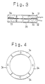
- a typical pressure sensor 26 is shown in Fig. 3.
- An insulator 33 and a piezo-electric film 34 are arranged between ring supports 31 and 32 of the pressure sensor 26.
- the piezo-electric film is divided into four equal segments 34.
- each of the four equal segments senses the direction and magnitude of the load distribution applied to the spindle.
- the thrust load applied to the spindle 12 can be directly sensed by the pressure sensors 25 and 26.
- the sensed thrust load is available for determining tool breakage or tool wear, which determination is itself conventional.
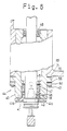
- Fig. 5 shows another embodiment in which a spindlehead 44 is shown as including a spindle 42 rotatably supported by a cylindrical support portion 40 with thrust bearings 46, 47 and 48.
- a cap member 41 is attached to the lower end of the support portion 40 by means of bolts 41a.
- a flange 70 of the support 40 is fixed to a frame 65 by means of a flange ring 60 and bolts 43.
- An annular pressure sensor 45 is arranged between the thrust bearing 47 the support portion 40.
- a pressure sensor 55 is arranged between the thrust bearing 46 and the support portion 40.
- a pressure sensor 71 is arranged between the flange 70 and the frame 65.
- a pressure sensor 56 is arranged between the flange 70 and the ring 60.
- Each of the pressure sensors 45, 55, 56 and 71 is, for example, a piezo-electric film pressure sensor.
- Both the paired pressure sensors 45 and 55 and the paired pressure sensors 56 and 71 sense the preloading applied through the bolts 41a and 43 and, thus, the sensed pressure data is obtained with accuracy.
- the invention is not restricted to the above-nentioned embodiments.
- pressure sensors of types ether than piezo-electric pressure sensors may be employed in this invention.
- the present invention offers the advantage that the thrust load alone, applied to the spindle or the tool, is directly sensed. Accordingly, pressure data can be obtained with a high degree of accuracy.
Landscapes
- Engineering & Computer Science (AREA)
- Mechanical Engineering (AREA)
- Chemical & Material Sciences (AREA)
- Combustion & Propulsion (AREA)
- Physics & Mathematics (AREA)
- General Physics & Mathematics (AREA)
- Machine Tool Sensing Apparatuses (AREA)
- Force Measurement Appropriate To Specific Purposes (AREA)
Abstract
Procédé de détection d'une force de poussée agissant sur la broche principale d'une machine-outil, permettant de détecter avec précision la force de poussée par la suppression des influences dues à la résistance d'un organe d'alimentation de broche principale. A cet effet une jauge de pression (25) est intercalée entre les paliers de butée (16, 17) d'une broche principale (12) et une section de support (20) de broche principale et une autre jauge de pression (26) est intercalée entre la section de support (20) de broche principale et un châssis (15). Ladite jauge de pression est, par exemple, du type utilisant un film piézoélectrique.
Applications Claiming Priority (2)
| Application Number | Priority Date | Filing Date | Title |
|---|---|---|---|
| JP63048682A JPH01222851A (ja) | 1988-03-03 | 1988-03-03 | 工作機械の主軸スラストカの検出方法 |
| JP48682/88 | 1988-03-03 |
Publications (2)
| Publication Number | Publication Date |
|---|---|
| EP0357798A1 true EP0357798A1 (fr) | 1990-03-14 |
| EP0357798A4 EP0357798A4 (en) | 1991-09-11 |
Family
ID=12810089
Family Applications (1)
| Application Number | Title | Priority Date | Filing Date |
|---|---|---|---|
| EP19890903264 Withdrawn EP0357798A4 (en) | 1988-03-03 | 1989-03-01 | Method for detecting thrust force of main spindle of machine tool |
Country Status (4)
| Country | Link |
|---|---|
| US (1) | US5042309A (fr) |
| EP (1) | EP0357798A4 (fr) |
| JP (1) | JPH01222851A (fr) |
| WO (1) | WO1989008005A1 (fr) |
Cited By (3)
| Publication number | Priority date | Publication date | Assignee | Title |
|---|---|---|---|---|
| EP0708915A4 (fr) * | 1993-01-05 | 1996-08-14 | Montronix Inc | Transducteur de boulon et procede de surveillance des forces de coupe dans une machine-outil |
| WO1999006808A1 (fr) * | 1997-08-01 | 1999-02-11 | Rotork Controls Limited | Capteur de poussee |
| EP1400310A1 (fr) * | 2002-09-19 | 2004-03-24 | CLAAS Fertigungstechnik GmbH | Procédé et dispositif pour la détermination de la profondeur de pénétration |
Families Citing this family (13)
| Publication number | Priority date | Publication date | Assignee | Title |
|---|---|---|---|---|
| DE4207324A1 (de) * | 1992-03-07 | 1993-09-09 | Schaeffler Waelzlager Kg | Impulswaelzlager zum beruehrungsfreien erfassen von drehzahlen mit magnetischen mitteln |
| DE19522543A1 (de) * | 1994-08-01 | 1996-02-08 | Ntn Toyo Bearing Co Ltd | Piezoelektrisches Film-Meßfühlersystem für Lager |
| FR2804353B1 (fr) * | 2000-01-28 | 2002-04-19 | Recoules | Machine pneumatique d'usinage |
| US7052215B2 (en) * | 2001-03-29 | 2006-05-30 | Kyocera Corporation | Cutting tool with sensor and production method therefor |
| DE10304405B4 (de) * | 2003-02-01 | 2012-10-04 | Hilti Aktiengesellschaft | Verfahren zur Regelung einer Kernbohrmaschine |
| EP1764186A1 (fr) * | 2005-09-14 | 2007-03-21 | Werner Kluft | Système de contrôle d'une opération d'usinage avec des capteurs piézoélectriques axiaux dans la broche de travail |
| SE533114C2 (sv) * | 2008-11-05 | 2010-06-29 | Atlas Copco Tools Ab | Borrspindelenhet |
| KR101033683B1 (ko) * | 2010-11-15 | 2011-05-12 | 김창호 | 압전 부하 센서가 장착된 고속 스핀들 장치 |
| CN102133647B (zh) * | 2009-12-24 | 2013-12-04 | 财团法人大邱机械部品研究院 | 高速主轴压电式负荷传感器 |
| KR101220409B1 (ko) * | 2010-12-20 | 2013-01-09 | 숭실대학교산학협력단 | 절삭력 측정이 가능한 밀링머신 |
| JP6948440B1 (ja) * | 2020-06-19 | 2021-10-13 | ミネベアミツミ株式会社 | 工具保持構造、荷重検出構造、及び工具状態監視システム |
| WO2021206147A1 (fr) * | 2020-04-10 | 2021-10-14 | ミネベアミツミ株式会社 | Structure porte-outil, structure de détection de charge, et système de surveillance d'état d'outil |
| JP6948432B1 (ja) * | 2020-04-10 | 2021-10-13 | ミネベアミツミ株式会社 | 工具保持構造、荷重検出構造、及び工具状態監視システム |
Family Cites Families (11)
| Publication number | Priority date | Publication date | Assignee | Title |
|---|---|---|---|---|
| US2978689A (en) * | 1955-05-09 | 1961-04-04 | Cross Co | Control mechanism for machine tools and the like |
| US3208311A (en) * | 1963-04-04 | 1965-09-28 | Cross Co | Tool detector |
| US3872285A (en) * | 1974-05-31 | 1975-03-18 | Westinghouse Electric Corp | Control system for sensing the vibration and lateral force on a cutting tool |
| JPS5824182Y2 (ja) * | 1977-06-20 | 1983-05-24 | 新日本工機株式会社 | 回転型工具のスラスト力検出装置 |
| JPS5638894A (en) * | 1979-09-07 | 1981-04-14 | Hitachi Electronics | Method of mounting part on flexible printed board |
| JPS58136208U (ja) * | 1982-03-10 | 1983-09-13 | 株式会社日立製作所 | ドリル破損検出用荷重変換器 |
| JPS6034295A (ja) * | 1983-08-03 | 1985-02-21 | 株式会社日立製作所 | 皮膚感覚センサ |
| JPS6158241A (ja) * | 1984-08-29 | 1986-03-25 | Hitachi Cable Ltd | 水平時差開放シヤツタ−方式のリ−ドフレ−ム整列装置 |
| US4741231A (en) * | 1986-04-14 | 1988-05-03 | The Warner & Swasey Company | Tool force sensor and method of making same |
| JPH0685854A (ja) * | 1992-08-31 | 1994-03-25 | Sanyo Electric Co Ltd | Msk変調回路 |
| DE4244404C2 (de) * | 1992-12-29 | 1999-09-02 | Daimler Chrysler Aerospace | Anwendungseinheit für eine Dichtmasse zum Abdichten von Nietverbindungen |
-
1988
- 1988-03-03 JP JP63048682A patent/JPH01222851A/ja active Pending
-
1989
- 1989-03-01 EP EP19890903264 patent/EP0357798A4/en not_active Withdrawn
- 1989-03-01 US US07/432,745 patent/US5042309A/en not_active Expired - Lifetime
- 1989-03-01 WO PCT/JP1989/000210 patent/WO1989008005A1/fr not_active Ceased
Non-Patent Citations (2)
| Title |
|---|
| No further relevant documents have been disclosed. * |
| See also references of WO8908005A1 * |
Cited By (3)
| Publication number | Priority date | Publication date | Assignee | Title |
|---|---|---|---|---|
| EP0708915A4 (fr) * | 1993-01-05 | 1996-08-14 | Montronix Inc | Transducteur de boulon et procede de surveillance des forces de coupe dans une machine-outil |
| WO1999006808A1 (fr) * | 1997-08-01 | 1999-02-11 | Rotork Controls Limited | Capteur de poussee |
| EP1400310A1 (fr) * | 2002-09-19 | 2004-03-24 | CLAAS Fertigungstechnik GmbH | Procédé et dispositif pour la détermination de la profondeur de pénétration |
Also Published As
| Publication number | Publication date |
|---|---|
| EP0357798A4 (en) | 1991-09-11 |
| US5042309A (en) | 1991-08-27 |
| WO1989008005A1 (fr) | 1989-09-08 |
| JPH01222851A (ja) | 1989-09-06 |
Similar Documents
| Publication | Publication Date | Title |
|---|---|---|
| US5042309A (en) | Apparatus and method for sensing a thrust load applied to a spindle of a machine tool | |
| US4551950A (en) | Truing apparatus for a grinding wheel with rounded corners | |
| US4694686A (en) | Cutting tool wear monitor | |
| US5027280A (en) | Machining apparatus having a main spindle supported by magnetic bearings | |
| US8950507B2 (en) | Device for preventing vibrations in a tool spindle | |
| US20080226409A1 (en) | Dental machining unit with tool spindle | |
| US4893514A (en) | Device for measuring forces in metal spinning lathes | |
| CA1243744A (fr) | Dispositif de controle de l'usure d'un outil de coupe | |
| US4697964A (en) | Boring machine | |
| JPH03500745A (ja) | 回転機械加工用に取り付けられた工具チップによって描かれる半径を自動的に測定する装置及び方法 | |
| CA1310385C (fr) | Methode de detection en service d'un outil rotatif use | |
| US5741981A (en) | Device and method of measuring the draw-in force for stationary and rotating spindle | |
| GB2168271A (en) | Method for determining the position of a workpiece in a numerically controlled machine and a numerically controlled machine for carrying out such a method | |
| EP1764187A3 (fr) | Procédé pour usiner une surface et simultanément mesurer des paramètres de la surface | |
| US3818334A (en) | Determining cutting tool force by measuring electrical resistance of a bearing | |
| JPH05138481A (ja) | 軸力検出手段付き直線案内装置 | |
| JPH039116A (ja) | ころがり軸受用自動予圧調整装置 | |
| JPH03149158A (ja) | トルク、スラスト、曲げ力検知スピンドル | |
| JP3570688B2 (ja) | 工具異常検出装置 | |
| US6605915B2 (en) | Numerical control apparatus for machine tool | |
| JP7416374B2 (ja) | 回転主軸の回転振れ制御方法および主軸装置 | |
| JPS63295178A (ja) | 研削盤の制御方法 | |
| JPS58192749A (ja) | 電気的接触検出法 | |
| JP7737116B2 (ja) | 工作機械 | |
| JPS62176756A (ja) | 研摩装置 |
Legal Events
| Date | Code | Title | Description |
|---|---|---|---|
| PUAI | Public reference made under article 153(3) epc to a published international application that has entered the european phase |
Free format text: ORIGINAL CODE: 0009012 |
|
| AK | Designated contracting states |
Kind code of ref document: A1 Designated state(s): DE FR GB IT |
|
| 17P | Request for examination filed |
Effective date: 19900119 |
|
| A4 | Supplementary search report drawn up and despatched |
Effective date: 19910723 |
|
| AK | Designated contracting states |
Kind code of ref document: A4 Designated state(s): DE FR GB IT |
|
| 17Q | First examination report despatched |
Effective date: 19920130 |
|
| STAA | Information on the status of an ep patent application or granted ep patent |
Free format text: STATUS: THE APPLICATION IS DEEMED TO BE WITHDRAWN |
|
| 18D | Application deemed to be withdrawn |
Effective date: 19931125 |