EP0357909B1 - Appareil électrique de commande à distance - Google Patents
Appareil électrique de commande à distance Download PDFInfo
- Publication number
- EP0357909B1 EP0357909B1 EP89112812A EP89112812A EP0357909B1 EP 0357909 B1 EP0357909 B1 EP 0357909B1 EP 89112812 A EP89112812 A EP 89112812A EP 89112812 A EP89112812 A EP 89112812A EP 0357909 B1 EP0357909 B1 EP 0357909B1
- Authority
- EP
- European Patent Office
- Prior art keywords
- remote
- remote control
- control transmitter
- control
- transmitter
- Prior art date
- Legal status (The legal status is an assumption and is not a legal conclusion. Google has not performed a legal analysis and makes no representation as to the accuracy of the status listed.)
- Expired - Lifetime
Links
Images


Classifications
-
- H—ELECTRICITY
- H03—ELECTRONIC CIRCUITRY
- H03J—TUNING RESONANT CIRCUITS; SELECTING RESONANT CIRCUITS
- H03J9/00—Remote-control of tuned circuits; Combined remote-control of tuning and other functions, e.g. brightness, amplification
- H03J9/06—Remote-control of tuned circuits; Combined remote-control of tuning and other functions, e.g. brightness, amplification using electromagnetic waves other than radio waves, e.g. light
-
- G—PHYSICS
- G08—SIGNALLING
- G08C—TRANSMISSION SYSTEMS FOR MEASURED VALUES, CONTROL OR SIMILAR SIGNALS
- G08C23/00—Non-electrical signal transmission systems, e.g. optical systems
- G08C23/04—Non-electrical signal transmission systems, e.g. optical systems using light waves, e.g. infrared
-
- G—PHYSICS
- G11—INFORMATION STORAGE
- G11B—INFORMATION STORAGE BASED ON RELATIVE MOVEMENT BETWEEN RECORD CARRIER AND TRANSDUCER
- G11B15/00—Driving, starting or stopping record carriers of filamentary or web form; Driving both such record carriers and heads; Guiding such record carriers or containers therefor; Control thereof; Control of operating function
- G11B15/02—Control of operating function, e.g. switching from recording to reproducing
- G11B15/023—Control of operating function, e.g. switching from recording to reproducing remotely controlled
-
- G—PHYSICS
- G11—INFORMATION STORAGE
- G11B—INFORMATION STORAGE BASED ON RELATIVE MOVEMENT BETWEEN RECORD CARRIER AND TRANSDUCER
- G11B33/00—Constructional parts, details or accessories not provided for in the other groups of this subclass
- G11B33/10—Indicating arrangements; Warning arrangements
-
- G—PHYSICS
- G08—SIGNALLING
- G08C—TRANSMISSION SYSTEMS FOR MEASURED VALUES, CONTROL OR SIMILAR SIGNALS
- G08C2201/00—Transmission systems of control signals via wireless link
- G08C2201/30—User interface
- G08C2201/32—Remote control based on movements, attitude of remote control device
-
- G—PHYSICS
- G08—SIGNALLING
- G08C—TRANSMISSION SYSTEMS FOR MEASURED VALUES, CONTROL OR SIMILAR SIGNALS
- G08C2201/00—Transmission systems of control signals via wireless link
- G08C2201/70—Device selection
- G08C2201/71—Directional beams
Definitions
- the invention relates to a remote-controlled electrical device according to the preamble of claim 1.
- a remote control transmitter is provided with which a user of the remote-controlled device sets the operating commands.
- the remote-controllable device contains a remote control receiver which receives the remote control signals emitted by the remote control transmitter and converts them into the corresponding control signals for setting and controlling the desired operating state.
- a remote control system is known with which a remotely controllable electrical device can be operated via a remote control transmitter which is remote from the remotely controllable device. Keys actuated from a keypad of the remote control transmitter call up associated control signals from a signal memory, which transmit them to the remote control receiver via a carrier wave formed in the remote control transmitter of the device to be operated remotely.
- the remote control receiver forms the corresponding switching and control signals for setting and controlling the device to be operated remotely.
- a menu is generally displayed on a screen and individual parts of the menu are selected by the user using a cursor which can be moved on the screen in the menu.
- a handheld remote control transmitter for this purpose, the remote control transmitter known from the publication contains several IR transmitter elements, whose radiation characteristics are strongly bundled and which are arranged slightly divergent in their radiation directions.
- the individual transmission elements are activated in a specific phase and time pattern and correspondingly received synchronously by the remote control receiver of the remote-controlled electrical device known from the publication. From this, angular position data are created in a direction detector of the device, which are adapted in an interface to the data input of a computer for controlling the cursor.
- the radiation fields for determining the angular offset are generated in the remote control transmitter.
- the remote control transmitter takes the necessary energy from its power supply, especially from the inserted batteries.
- the invention is therefore based on the object, in the case of remotely controllable electrical devices with a large number of adjustable operating states and operating sequences in which, in order to simplify the process of remote control, at least essential operating states or operating sequences are set by storing the pointing direction of the remote control transmitter from a nominal pointing direction and energy-requiring radiation fields not to be generated in the remote control transmitter.
- the dependent claim 2 characterizes an advantageous embodiment of the invention.
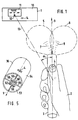
- the remote setting of a remotely controllable electrical device which is remotely controlled by a remote control transmitter 3 held in the hand 2 of a user, is explained in more detail using an exemplary embodiment shown in FIGS. 1 and 2.
- the remote control transmitter 3 contains a push button 4 which is actuated with the thumb of the hand 2 and which serves to switch on the transmission operating state of the remote control transmitter and to set the operating position of the remote control transmitter to the user's hand.
- the remote control transmitter 3 transmits four carrier waves in the transmission operating state, which are identified in a certain way from one another, for example by different carrier wave frequencies and / or by different identification signals modulated onto the carrier waves.
- the spatial intensity of the radiation field 5 and 6 of two of these carrier waves 7 and 8 is shown schematically in FIG. 1.
- the radiation field of these carrier waves is essentially limited by planes, not shown separately in FIG. 1, which are perpendicular to one another and in which the pointer direction 9 of the remote control transmitter 3 extends.
- the remote-controlled electrical device 1 shown in FIG. 1 contains on its front side 10 a display 11 which shows the operating state of the device 1.
- this display 11 is a marking element 12, to which the remote control transmitter 3 for remote control of the device 1 is normally directed, so that the pointer direction 9 of the remote control transmitter 3 falls into a line 13, which is from the current location of the remote control transmitter 3 held in the hand runs to the marking element 12 and is designated here with the marking direction 13.
- the remote control transmitter 3 is pivoted in a certain direction (to the right in the exemplary embodiment shown) by a storage angle alpha from the marking direction 13.
- the Alpha shelf must be at least so large that the radiation field (6) of at least one carrier wave (8) no longer effectively reaches a receiving element 14 of the electrical device 1 provided for receiving these carrier waves. As a result, a directional storage of the remote control transmitter 3 is detected in the electrical device 1 as long as the remote control transmitter is in the transmit operating state.
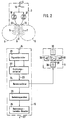
- FIG. 2 shows a block diagram of the remote control transmitter 3 shown in FIG. 1 and a remote control receiver 15 contained in the remote-controllable electrical device 1.
- the push button 4 is a component of an electrical switch 16, which switches carrier wave generators 17, 18 in the activated state. These carrier wave generators generate the specially marked carrier waves 7, 8, which the remote control transmitter 3 emits in the transmission operating state via transmission elements 19, 20 of the remote control transmitter.
- the transmission elements 19, 20 and their attachment in the housing of the remote control transmitter 3 are designed in such a way that they generate the spatial radiation fields 5, 6 specified above.
- a signal decoder 21 of the remote control receiver 15 of the electrical device 1 the identifier of the carrier waves received via the receiving element 14 of the remote control receiver 15 is checked, and from the reception field strength of the approved carrier waves 7, 8, the signal angle ⁇ of the remote control transmitter 3 characterizing signals generated, from which a direction detector 22 forms a control signal 23 for a command selector 24 which is dependent on the angular offset alpha.
- this control signal 23 generates a program sequence which is also dependent on the operating state of the electrical device 1, in which the electrical device 1 was located before the control signal 23 occurred, and which executes the operating commands required for the desired operating state or operating sequence an instruction memory 25.
- An operating command converter 26 of the remote control receiver 15 converts the retrieved operating commands, corresponding function control signals 27 in the electrical device 1 for setting the operating state or operating sequence of the electrical device selected with the remote control transmitter 3.
- the command selector 24 also controls a display 11 of the remote-controlled electrical device 1.
- the remotely controllable electrical device 1 is a video recorder.
- the lower picture 28 of the display 11 identifies the stand-by operating state, the middle picture 29 the normal running state (PLAY) and the upper picture 30 the still picture or pause state of the video recorder.
- the pictures 31 and 32 left and right of the middle picture 29 give the running direction and running speed of the video signal carrier in the various set operating states of the video recorder. If the user pivots the remote control transmitter 3 to the right in the exemplary embodiment shown and then switches the remote control transmitter to the transmission operating state, then he switches on the fast forward running of the video signal carrier when the video recorder was in the stand-by operating state. To stop this quick run, the user actuates the remote control transmitter in a position of the remote control transmitter directed downwards. When the remote control unit is in a handling position upwards, the video recorder is switched to the normal playback state PLAY and, after a further actuation of the pushbutton 4, is switched to the still image operating state in this position.
- the carrier wave generator 17 for the carrier wave 7b which is provided for forming signals corresponding to the angular offset alpha of the remote control transmitter 3b of this device, is arranged in the remote control receiver 15b.
- a transmitter element 19 of the remote control receiver radiates this carrier wave 7b without limit.
- the carrier wave 7b is a polarizable infrared light wave of a certain wavelength and optionally provided with an additional identifier.
- the associated remote control transmitter 3b contains four reflection elements 36.1 to 36.4, each of which has a polarization filter 37.1 to 37.4 placed in front of it.
- Each of these polarization filters contains a different polarization, indicated by an arrow in the drawing, so that four differently polarized light sources are produced on the remote control transmitter 3b.
- the polarization filters and their attachment in the housing of the remote control transmitter 3b are such that their spatial reception and reflection fields 38, 1 to 38, 4 are mutually essentially delimited by two mutually perpendicular planes in which the pointer direction 9 of the remote control transmitter 3b runs.
- the remote-controlled electrical device 1 contains four receiving elements 14.1 to 14.4, to which differently polarized polarization filters 39.1 to 39.4 are placed.
- the polarization of the reflected light waves is an identifier of these light waves.
- the receiving elements 14, 1 to 14, 4 are connected to a signal detector 21b of the remote control receiver 15b of the electrical device 1, which measures the received field strengths of the received reflected light waves and forms signals for the direction detector 22 of the remote control receiver 15b that indicate the storage of the pointer direction of the remote control transmitter 3b .
- the remote control transmitter 3b of the exemplary embodiment shown in FIG. 4 also contains an auxiliary carrier wave generator 40 which generates an auxiliary carrier shaft 41 when the pushbutton 4 of the remote control transmitter 3b is actuated.
- This auxiliary carrier shaft 41 which is transmitted from a transmitting element 42 of the remote control transmitter 3b to a receiving element 43 of the remote control receiver 15b, switches on the remote control receiver 15b of the electrical device 1 and thus the remote control device of the remote-controlled electrical device via the direction detector 22.
- the video recorder contains a remote control receiver 15c with which it receives the remote control signals emitted by a remote control transmitter 3c on a carrier wave 45 and converts the control signals 27 for a control circuit 57 of the video recorder.
- the remote control receiver 15c contains a receiving element 46, which converts the received carrier wave 45 into an electrical signal and feeds it to a downstream signal decoder 47. The latter decodes the control signals 23, which are formed in a direction detector 22 of the remote control transmitter 3c and are dependent on the angular offset alpha of the remote control transmitter 3c, for the corresponding control of the command selector 24 of the remote control receiver 15c.
- a menu control circuit 48 of the remote control receiver is also connected to the command selector 24 and, via a video signal part 58, displays the program run status of the command selector 24 on the screen 49 of the television 44 connected to the video recorder.
- the screen 49 of the television set 44 shows both the display (11) for the remote control receiver 15c and the visually visible marking element (12) for the user of the devices as well as the transmission element (19) for the radiation of a carrier wave 7, with the help of which the angular offset alpha of the pointer direction 9 of the remote control transmitter 3c from the direction 13 to the visually visible marking element (12) is determined.
- the carrier wave 7 emitted by the screen 49 is the light information of the video images reproduced by the screen.
- This light information contains as an identifier the line synchronizing pulses with the line frequency of a line generator 59 of the television receiver 44 as a repetition frequency.
- This light information is received by means of the direction-dependent receiving elements 50 of the remote control transmitter 3c and is supplied as electrical signals to a signal decoder 21 which measures the intensity of this light information and outputs signals corresponding to this intensity to the direction detector 22 of the remote control transmitter 3c.
- the control signals 23 generated therefrom by the direction detector 22 and characterizing the angular offset alpha of the remote control transmitter are modulated onto the second carrier wave 45 generated in a carrier wave generator 51 and transmitted to the remote control receiver 15c via a transmission element 52 of the remote control transmitter 3c.
- a remote control transmitter 3c which is a component of the exemplary embodiment shown in FIG. 5, is shown in perspective, essentially on its transmitting and receiving side.
- This side is the end face 53 of the housing 54 of the remote control transmitter in its pointer direction 9.
- the end face 53 contains four shading walls 55, which together with a recess 56, in which the receiving elements 50 are arranged, form a spatial receiving field 57 for each receiving element, which does not essentially extend over fictitious levels that lie in the shading walls.
- the transmission element 52 is for radiation of the carrier wave 45 containing the remote control signals.
- the push button 4 is arranged, which is provided for switching on the remote control device and which determines the operating position of the remote control transmitter 3c in the hand 2 of the user.
- the video recorder is controlled in its operating states and operating sequences via a menu program arranged in the command selector 24.
- a menu is provided for each operating level.
- the remote control transmitter 3c is pivoted to the right or left to the side with the pushbutton 4 actuated until the desired menu, for example, on the screen 49.
- the menu M4 is particularly illuminated. Then, by holding the remote control transmitter 3c down or up, the desired operating setting M43 is selected from the possible operating settings M41 to M45 of the set operating level M4.
- the particularly illuminated menu displays (M4 and M43) on the screen 49 reflect the setting of the command selector 24, which in the exemplary embodiment shown activates the command selector 24 of the remote control receiver 15c by pressing the pushbutton 4 with the remote control transmitter 3c directed towards the center of the screen 49, so that it retrieves the operating command required for the selected operating state or operating sequence of the video recorder from the command memory 25.
- These commands are in the command converter 26 in the for Control circuit 57 of the video recorder required function control signals 27 converted.
- the menu display on the screen 49 goes out when the operating commands are called up from the command memory.
Landscapes
- Physics & Mathematics (AREA)
- General Physics & Mathematics (AREA)
- Electromagnetism (AREA)
- Engineering & Computer Science (AREA)
- Computer Hardware Design (AREA)
- Microelectronics & Electronic Packaging (AREA)
- Selective Calling Equipment (AREA)
- Details Of Television Systems (AREA)
- Transmitters (AREA)
Claims (3)
- Appareil électrique pouvant être commandé à distance- comportant un récepteur de télécommande et un émetteur de télécommande actionné manuellement, sans fil, éloigné du récepteur de télécommande et comportant au moins un élément émetteur (52), entre lesquels des éléments émetteurs envoient des signaux de télécommande à des éléments récepteurs pour caractériser la déviation angulaire (alpha) de la direction de pointage (9) de l'émetteur de télécommande (3) en fonctionnement, par rapport à une direction de repérage (13) qui relie l'émetteur de télécommande et un élément de repérage (12) visuel sur le récepteur de télécommande (15),- et comportant un détecteur de direction (22) qui transmet à un sélecteur d'instructions (24) des signaux de commande (23) qui correspondent à la déviation angulaire de l'émetteur de télécommande, pour le réglage d'états de fonctionnement définis de l'appareil pouvant être commandé à distance,
caractérisé par le fait- que le récepteur de télécommande (15c) comprend un générateur d'onde porteuse (59) qui produit une onde porteuse (7) possédant une caractéristique définie, et un élément émetteur (19) pour l'émission de cette onde porteuse,- que sont disposés dans l'émetteur de télécommande (3c) :-- un bouton-poussoir (4) destiné à déclencher le fonctionnement de l'émetteur de télécommande (3c)-- plusieurs éléments récepteurs (50) pour la réception de l'onde porteuse (7) dont le champ de réception dans l'espace est limité par des plans dans lesquels passe la direction de pointage (9) de l'émetteur de télécommande-- le détecteur de direction (22) qui est réglé sur la caractéristique de l'onde porteuse, et-- un deuxième générateur d'onde porteuse (51) qui est relié à l'élément émetteur (52)- et que le détecteur de direction (22) produit des signaux de commande (23) qui sont modulés en tant que signaux de télécommande sur l'onde porteuse (45) produite par le deuxième générateur d'onde porteuse (51). - Appareil électrique pouvant être commandé à distance selon la revendication 1, caractérisé par le fait que l'écran (49) du récepteur de télécommande (15c) est simultanément un élément émetteur pour l'émission de l'onde porteuse (7) et un élément de repérage et que le générateur d'onde porteuse (59) qui produit une onde porteuse (7) avec une caractéristique définie, est le générateur de lignes du récepteur de télécommande (15c).
- Appareil électrique pouvant être commandé à distance- comportant un récepteur de télécommande et un émetteur de télécommande actionné manuellement, sans fil, éloigné du récepteur de télécommande et comportant au moins un élément émetteur (42), entre lesquels des éléments émetteurs envoient des signaux de télécommande à des éléments récepteurs pour caractériser la déviation angulaire (alpha) de la direction de pointage (9) de l'émetteur de télécommande (3) en fonctionnement, par rapport à une direction de repérage (13) qui relie l'émetteur de télécommande et un élément de repérage (12) visuel sur le récepteur de télécommande (15),- et comportant un détecteur de direction (22) qui transmet à un sélecteur d'instructions (24) des signaux de commande (23) qui correspondent à la déviation angulaire de l'émetteur de télécommande, pour le réglage d'états de fonctionnement définis de l'appareil pouvant être commandé à distance,
caractérisé par le fait- que le récepteur de télécommande (15b) comporte une source lumineuse (19) pour la production d'une lumière (7b) polarisable possédant une longueur d'onde définie ou une caractéristique définie,- que l'émetteur de télécommande (3b) comprend un bouton-poussoir (4) pour déclencher l'émission et plusieurs éléments de réflexion (36, 37) polarisés différemment dont le champ de réception et de réflexion (38) dans l'espace est limité par des plans dans lesquels passe la direction de pointage (9) de l'émetteur de télécommande- et que sont montés en amont des éléments récepteurs (14) du récepteur de télécommande (15b), des filtres de polarisation (39) polarisés conformément à l'agencement des éléments de réflexion (36, 37) polarisés, de l'émetteur de télécommande.
Applications Claiming Priority (2)
| Application Number | Priority Date | Filing Date | Title |
|---|---|---|---|
| DE3828334A DE3828334C2 (de) | 1988-08-20 | 1988-08-20 | Fernbedienbares elektrisches Gerät |
| DE3828334 | 1988-08-20 |
Publications (2)
| Publication Number | Publication Date |
|---|---|
| EP0357909A1 EP0357909A1 (fr) | 1990-03-14 |
| EP0357909B1 true EP0357909B1 (fr) | 1994-11-17 |
Family
ID=6361266
Family Applications (1)
| Application Number | Title | Priority Date | Filing Date |
|---|---|---|---|
| EP89112812A Expired - Lifetime EP0357909B1 (fr) | 1988-08-20 | 1989-07-13 | Appareil électrique de commande à distance |
Country Status (4)
| Country | Link |
|---|---|
| EP (1) | EP0357909B1 (fr) |
| JP (1) | JPH0671349B2 (fr) |
| AT (1) | ATE114199T1 (fr) |
| DE (2) | DE3828334C2 (fr) |
Families Citing this family (19)
| Publication number | Priority date | Publication date | Assignee | Title |
|---|---|---|---|---|
| JPH0435365A (ja) * | 1990-05-28 | 1992-02-06 | Matsushita Electric Ind Co Ltd | 遠隔操作装置 |
| WO1993007602A1 (fr) * | 1991-10-03 | 1993-04-15 | Thomson Consumer Electronics S.A. | Procede et dispositif concernant une telecommande agissant selon l'angle d'emission |
| DE69226242T2 (de) * | 1991-11-28 | 1998-11-19 | Sony Corp | Videosignalwiedergabegerät |
| US6603420B1 (en) | 1999-12-02 | 2003-08-05 | Koninklijke Philips Electronics N.V. | Remote control device with motion-based control of receiver volume, channel selection or other parameters |
| FR2827415B1 (fr) * | 2001-07-12 | 2003-12-12 | Somfy | Dispositif de commande a distance de dispositif electrique |
| US6990639B2 (en) | 2002-02-07 | 2006-01-24 | Microsoft Corporation | System and process for controlling electronic components in a ubiquitous computing environment using multimodal integration |
| US7233316B2 (en) * | 2003-05-01 | 2007-06-19 | Thomson Licensing | Multimedia user interface |
| WO2007036818A1 (fr) * | 2005-09-29 | 2007-04-05 | Koninklijke Philips Electronics N.V. | Dispositif de telecommande et systeme associe |
| WO2009109928A2 (fr) * | 2008-03-07 | 2009-09-11 | Philips Intellectual Property & Standards Gmbh | Procédé de commande d'un agencement de dispositifs |
| EP2291833A1 (fr) * | 2008-06-19 | 2011-03-09 | Koninklijke Philips Electronics N.V. | Technologie de pointage à commande à distance |
| US10642934B2 (en) | 2011-03-31 | 2020-05-05 | Microsoft Technology Licensing, Llc | Augmented conversational understanding architecture |
| US9298287B2 (en) | 2011-03-31 | 2016-03-29 | Microsoft Technology Licensing, Llc | Combined activation for natural user interface systems |
| US9760566B2 (en) | 2011-03-31 | 2017-09-12 | Microsoft Technology Licensing, Llc | Augmented conversational understanding agent to identify conversation context between two humans and taking an agent action thereof |
| US9842168B2 (en) | 2011-03-31 | 2017-12-12 | Microsoft Technology Licensing, Llc | Task driven user intents |
| US9064006B2 (en) | 2012-08-23 | 2015-06-23 | Microsoft Technology Licensing, Llc | Translating natural language utterances to keyword search queries |
| CN104346920A (zh) * | 2014-10-28 | 2015-02-11 | 河海大学 | 一对多遥控装置识别遥控对象的方法及一对多遥控装置 |
| EP3174026A1 (fr) * | 2015-11-24 | 2017-05-31 | Hella KGaA Hueck & Co | Commande à distance pour des applications automobiles |
| TWI691908B (zh) * | 2017-02-16 | 2020-04-21 | 小綠草股份有限公司 | 自拍系統及方法 |
| TWI628954B (zh) * | 2017-02-16 | 2018-07-01 | 小綠草股份有限公司 | 自拍系統及方法 |
Family Cites Families (14)
| Publication number | Priority date | Publication date | Assignee | Title |
|---|---|---|---|---|
| JPS5274788A (en) * | 1975-12-17 | 1977-06-23 | Matsushita Electric Ind Co Ltd | Transmitter of remote operating device |
| US4150285A (en) * | 1977-12-27 | 1979-04-17 | United Technologies Corporation | Remote optical display designator |
| DE3228354C2 (de) * | 1982-07-29 | 1985-10-10 | Standard Elektrik Lorenz Ag, 7000 Stuttgart | Benutzerführende Bedienung bei Geräten der Unterhaltungselektronik |
| US4565999A (en) * | 1983-04-01 | 1986-01-21 | Prime Computer, Inc. | Light pencil |
| JPS6045546U (ja) * | 1983-09-05 | 1985-03-30 | ソニー株式会社 | リモ−トコントロ−ル装置 |
| US4682159A (en) * | 1984-06-20 | 1987-07-21 | Personics Corporation | Apparatus and method for controlling a cursor on a computer display |
| JPS6144943U (ja) * | 1984-08-24 | 1986-03-25 | ソニー株式会社 | 遠隔操作装置 |
| FR2583197A1 (fr) * | 1985-06-07 | 1986-12-12 | Thomson Csf | Systeme de commande de positionnement d'une marque sur un ecran et application a la commande d'ordres a distance |
| JPS6266797A (ja) * | 1985-09-18 | 1987-03-26 | Seiko Epson Corp | リモ−トコントロ−ル送信集積回路 |
| JPS62167434U (fr) * | 1986-04-11 | 1987-10-23 | ||
| JPS62191282U (fr) * | 1986-05-26 | 1987-12-05 | ||
| DE3751226T2 (de) * | 1986-11-27 | 1995-12-07 | Fenner David Fenton | Fernsteuerungssysteme. |
| US4745402A (en) * | 1987-02-19 | 1988-05-17 | Rca Licensing Corporation | Input device for a display system using phase-encoded signals |
| EP0355172B1 (fr) * | 1988-08-06 | 1994-07-20 | Deutsche ITT Industries GmbH | Système de commande à distance |
-
1988
- 1988-08-20 DE DE3828334A patent/DE3828334C2/de not_active Expired - Fee Related
-
1989
- 1989-07-13 AT AT89112812T patent/ATE114199T1/de not_active IP Right Cessation
- 1989-07-13 EP EP89112812A patent/EP0357909B1/fr not_active Expired - Lifetime
- 1989-07-13 DE DE58908645T patent/DE58908645D1/de not_active Expired - Lifetime
- 1989-08-21 JP JP1214754A patent/JPH0671349B2/ja not_active Expired - Lifetime
Also Published As
| Publication number | Publication date |
|---|---|
| ATE114199T1 (de) | 1994-12-15 |
| DE3828334C2 (de) | 1994-02-03 |
| DE58908645D1 (de) | 1994-12-22 |
| JPH02186799A (ja) | 1990-07-23 |
| JPH0671349B2 (ja) | 1994-09-07 |
| DE3828334A1 (de) | 1990-02-22 |
| EP0357909A1 (fr) | 1990-03-14 |
Similar Documents
| Publication | Publication Date | Title |
|---|---|---|
| EP0357909B1 (fr) | Appareil électrique de commande à distance | |
| EP0355172B1 (fr) | Système de commande à distance | |
| DE69125654T2 (de) | Fernsteueranordnung zur Steuerung eines Fernsehempfängers | |
| DE69423615T2 (de) | System und methode zur automatischen aufzeichnung von fernsehprogrammen in fernsehsystemen mit tunern ausserhalb der videorekorder | |
| DE69027244T2 (de) | Fernsteuerung für elektronische Apparate | |
| DE3851040T2 (de) | Rekonfigurierbare Fernsteuervorrichtung. | |
| US5187469A (en) | Universal remote control including quick touch function | |
| DE69330589T2 (de) | Steuervorrichtung für Elektronikgeräte | |
| DE60113326T2 (de) | Verfahren und Vorrichtung zur Auslösung einer Funktion | |
| DE3821572A1 (de) | Fernbedienungsanordnung | |
| DE2755633A1 (de) | Fernsteuerung zum steuern, ein- und umschalten von variablen und festen geraetefunktionen und funktionsgroessen in nachrichtentechn. geraeten | |
| DE3322729A1 (de) | Fernbedienungssystem fuer elektrische und elektronische geraete, insbesondere fuer geraete der unterhaltungselektronik | |
| DE69107881T2 (de) | Fernsteuersystem. | |
| DE4135293A1 (de) | Betriebsartumwandlungsverfahren fuer eine multifunktionale programmierbare fernbedienung | |
| DE19744941C2 (de) | Verfahren zur Fernbedienung einer Präsentationseinrichtung | |
| JPS6476218A (en) | Menu selection and display control system | |
| EP0512206B1 (fr) | Procédé pour choisir un mode de fonctionnement d'un appareil de divertissement | |
| DE3817621A1 (de) | Fernsteuerungssystem mit einer batterie- oder akkumulatorgespeisten fernbedienungseinheit | |
| DE102004027852B4 (de) | Röngtenanlage | |
| DE19737651A1 (de) | Verfahren zur Fernbedienung elektrischer und/oder elektronischer Geräte und Einrichtung zur Durchführung des Verfahrens | |
| DE2831014A1 (de) | Kombiniertes rundfunk/fernseh- empfangsgeraet mit nur einem ton-wiedergabeteil | |
| DE8226651U1 (de) | Auf felder wie infrarotlicht ansprechendes elektrisches geraet | |
| DE602006000488T2 (de) | Konfigurationsgerät für Gebäudeaktuatoren | |
| DE19845566A1 (de) | Navigationsinterface zur Bewegung in virtuellen Welten | |
| EP0150367A2 (fr) | Dispositif de commande pour unité de visualisation |
Legal Events
| Date | Code | Title | Description |
|---|---|---|---|
| PUAI | Public reference made under article 153(3) epc to a published international application that has entered the european phase |
Free format text: ORIGINAL CODE: 0009012 |
|
| AK | Designated contracting states |
Kind code of ref document: A1 Designated state(s): AT DE FR GB IT NL |
|
| 17P | Request for examination filed |
Effective date: 19901023 |
|
| RAP1 | Party data changed (applicant data changed or rights of an application transferred) |
Owner name: NOKIA (DEUTSCHLAND) GMBH |
|
| 17Q | First examination report despatched |
Effective date: 19930604 |
|
| GRAA | (expected) grant |
Free format text: ORIGINAL CODE: 0009210 |
|
| AK | Designated contracting states |
Kind code of ref document: B1 Designated state(s): AT DE FR GB IT NL |
|
| REF | Corresponds to: |
Ref document number: 114199 Country of ref document: AT Date of ref document: 19941215 Kind code of ref document: T |
|
| GBT | Gb: translation of ep patent filed (gb section 77(6)(a)/1977) |
Effective date: 19941121 |
|
| REF | Corresponds to: |
Ref document number: 58908645 Country of ref document: DE Date of ref document: 19941222 |
|
| ITF | It: translation for a ep patent filed | ||
| ET | Fr: translation filed | ||
| PLBE | No opposition filed within time limit |
Free format text: ORIGINAL CODE: 0009261 |
|
| STAA | Information on the status of an ep patent application or granted ep patent |
Free format text: STATUS: NO OPPOSITION FILED WITHIN TIME LIMIT |
|
| 26N | No opposition filed | ||
| REG | Reference to a national code |
Ref country code: GB Ref legal event code: IF02 |
|
| REG | Reference to a national code |
Ref country code: GB Ref legal event code: 732E |
|
| NLS | Nl: assignments of ep-patents |
Owner name: ELDOR ELEKTRONIK SANAYI VE TICARET A.S. Owner name: MIVAR DI CARLO VICHI S.A.P.A. |
|
| REG | Reference to a national code |
Ref country code: FR Ref legal event code: TP |
|
| PGFP | Annual fee paid to national office [announced via postgrant information from national office to epo] |
Ref country code: DE Payment date: 20080729 Year of fee payment: 20 |
|
| PGFP | Annual fee paid to national office [announced via postgrant information from national office to epo] |
Ref country code: FR Payment date: 20080722 Year of fee payment: 20 Ref country code: AT Payment date: 20080725 Year of fee payment: 20 Ref country code: IT Payment date: 20080724 Year of fee payment: 20 Ref country code: NL Payment date: 20080724 Year of fee payment: 20 |
|
| PGFP | Annual fee paid to national office [announced via postgrant information from national office to epo] |
Ref country code: GB Payment date: 20080723 Year of fee payment: 20 |
|
| REG | Reference to a national code |
Ref country code: GB Ref legal event code: PE20 Expiry date: 20090712 |
|
| NLV7 | Nl: ceased due to reaching the maximum lifetime of a patent |
Effective date: 20090713 |
|
| PG25 | Lapsed in a contracting state [announced via postgrant information from national office to epo] |
Ref country code: NL Free format text: LAPSE BECAUSE OF EXPIRATION OF PROTECTION Effective date: 20090713 Ref country code: GB Free format text: LAPSE BECAUSE OF EXPIRATION OF PROTECTION Effective date: 20090712 |