EP0357939A2 - Drehrohr - Google Patents
Drehrohr Download PDFInfo
- Publication number
- EP0357939A2 EP0357939A2 EP89113941A EP89113941A EP0357939A2 EP 0357939 A2 EP0357939 A2 EP 0357939A2 EP 89113941 A EP89113941 A EP 89113941A EP 89113941 A EP89113941 A EP 89113941A EP 0357939 A2 EP0357939 A2 EP 0357939A2
- Authority
- EP
- European Patent Office
- Prior art keywords
- rotary tube
- rotary
- rotating
- sealing
- outer circumference
- Prior art date
- Legal status (The legal status is an assumption and is not a legal conclusion. Google has not performed a legal analysis and makes no representation as to the accuracy of the status listed.)
- Granted
Links
Images
Classifications
-
- F—MECHANICAL ENGINEERING; LIGHTING; HEATING; WEAPONS; BLASTING
- F27—FURNACES; KILNS; OVENS; RETORTS
- F27B—FURNACES, KILNS, OVENS OR RETORTS IN GENERAL; OPEN SINTERING OR LIKE APPARATUS
- F27B7/00—Rotary-drum furnaces, i.e. horizontal or slightly inclined
- F27B7/20—Details, accessories or equipment specially adapted for rotary-drum furnaces
- F27B7/22—Rotary drums; Supports therefor
- F27B7/2206—Bearing rings
-
- F—MECHANICAL ENGINEERING; LIGHTING; HEATING; WEAPONS; BLASTING
- F27—FURNACES; KILNS; OVENS; RETORTS
- F27B—FURNACES, KILNS, OVENS OR RETORTS IN GENERAL; OPEN SINTERING OR LIKE APPARATUS
- F27B7/00—Rotary-drum furnaces, i.e. horizontal or slightly inclined
- F27B7/20—Details, accessories or equipment specially adapted for rotary-drum furnaces
- F27B7/22—Rotary drums; Supports therefor
- F27B7/24—Seals between rotary and stationary parts
-
- F—MECHANICAL ENGINEERING; LIGHTING; HEATING; WEAPONS; BLASTING
- F27—FURNACES; KILNS; OVENS; RETORTS
- F27B—FURNACES, KILNS, OVENS OR RETORTS IN GENERAL; OPEN SINTERING OR LIKE APPARATUS
- F27B7/00—Rotary-drum furnaces, i.e. horizontal or slightly inclined
- F27B7/02—Rotary-drum furnaces, i.e. horizontal or slightly inclined of multiple-chamber or multiple-drum type
- F27B2007/022—Rotary-drum furnaces, i.e. horizontal or slightly inclined of multiple-chamber or multiple-drum type the drum having a non-uniform section along its length
-
- F—MECHANICAL ENGINEERING; LIGHTING; HEATING; WEAPONS; BLASTING
- F27—FURNACES; KILNS; OVENS; RETORTS
- F27B—FURNACES, KILNS, OVENS OR RETORTS IN GENERAL; OPEN SINTERING OR LIKE APPARATUS
- F27B7/00—Rotary-drum furnaces, i.e. horizontal or slightly inclined
- F27B7/20—Details, accessories or equipment specially adapted for rotary-drum furnaces
- F27B7/22—Rotary drums; Supports therefor
- F27B7/2206—Bearing rings
- F27B2007/2233—Bearing rings the ring being fixed to the drum, e.g. welded
-
- Y—GENERAL TAGGING OF NEW TECHNOLOGICAL DEVELOPMENTS; GENERAL TAGGING OF CROSS-SECTIONAL TECHNOLOGIES SPANNING OVER SEVERAL SECTIONS OF THE IPC; TECHNICAL SUBJECTS COVERED BY FORMER USPC CROSS-REFERENCE ART COLLECTIONS [XRACs] AND DIGESTS
- Y10—TECHNICAL SUBJECTS COVERED BY FORMER USPC
- Y10S—TECHNICAL SUBJECTS COVERED BY FORMER USPC CROSS-REFERENCE ART COLLECTIONS [XRACs] AND DIGESTS
- Y10S277/00—Seal for a joint or juncture
- Y10S277/903—Seal for rotating kiln or drum
Definitions
- the invention relates to a driven on the outer circumference and by means of axially symmetrically arranged on the outer circumference of the rotating rings on the outer circumference of the rotating rings running on rollers with pipes or sockets provided in the region of the rotating pipe ends adjoining the rotating pipe ends for product entry, product gas discharge and solid outlet for thermal treatment, smoldering or pyrolysis liquid or solid substances or mixed phases by means of indirect heating through a stationary muffle arranged around the rotary tube jacket.
- Such devices were used on the discharge side were arranged slightly inclined downwards against the horizontal, often provided as so-called ball ovens with a loading of steel balls, in order to use flat ribs welded in the longitudinal direction as a driver to cause the balls to be carried as high as possible in the rotating oven, and then to fall down the crusts that form (see page 254, loc. cit.).
- smoldering can also result in waste materials such as plastic waste, residues contaminated with hydrocarbons, contaminated soils, biomass, sludge and the like. Like. be worked up on liquid products and smoldering tar in addition to smoldering gas and smoldering coke.
- the heat losses associated with the races and also the drive of the rotary tube which is often carried out as a chain drive via gears, also lead to a deterioration in the liquid product yield due to premature condensation with subsequent cracking and polymerization reactions.
- the known rotary tube designs were usually designed with a soft, axial expansion compensator for the rotary tube head.
- the sealing function of the rotating sealing part which is pressed onto the stationary sealing part, for example with a pressure roller, and contains two sealing packings is considerably impaired by rotary tube eccentricities.
- the task of the invention is derived to contribute to better thermal and chemical efficiency through improved thermal insulation, in particular in the area of the races of the rotary tube.
- Another object is to contribute to an improved sealing function and a significantly increased service life of the sealing packs between the moving and the stationary parts of the rotary tube by means of an improved structural arrangement of the elements of the mechanical seal system.
- An advantageous embodiment of the mechanical seal system according to the invention is that it has an elastic sealing part with a hydraulic, pneumatic or spring-loaded compensator unit to compensate for the wear of the actual sealing elements.
- the proposed mechanical seal system with, for example, a ball-bearing frame construction and a non-positive connection to Rotary tube head allows the rotary tube head to participate in all movements of the rotary tube with the exception of the rotary movement around the axis of rotation.
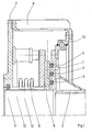
- a with the rotating part of the seal screwed flange 1 is with the entire circumference
- the outer jacket of the rotary tube 2 is welded at its ends.
- the sealing elements 3, 4, 5, z. B. packings, metal rings or the like Made of suitable materials mechanically exactly, whereby a reliable seal is effected in cooperation with the standing sealing flange 6.
- a sealing gas or a sealing liquid can be supplied by means of through valves or the like in order to create a flow in the direction opposite the space to be sealed of the inside of the rotary tube to ensure sufficient low overpressure.
- a further flange 7 is arranged as part of a frame structure 8, which can be designed, for example, as a welded construction, in such a way that a compensator unit 9 is welded in between these two flanges.
- This compensator unit 9 forms the elastic part of the seal and is used in particular to compensate for the wear of the sealing elements. It is designed as a metal compensator, for example as a bellows.
- the contact pressure of the sealing flange against the sealing elements can be kept constant by means of spring 10, hydraulics or pneumatics the wear of the sealing elements 3, 4, 5 can be compensated for within certain limits.
- a further sealing space is formed by a sealing element 11 between flange 7 and rotary tube head 12, which protects the components of the sealing system from the partially chemically aggressive pyrolysis gases, coke deposits and the like. Protects.
- the non-rotating part of the seal is expediently secured against the moment exerted by the rotating part by means of torque locks, not shown in the figure, in the form of rigid rod connections between the frame construction and the standing sealing flange.
- the two non-rotating flanges 6 and 7 of the sealing system are kept parallel by the stationary frame construction 8 in all practical operating conditions.
- the ball slewing ring 13 is screwed to its inner ring, the outer ring is firmly connected, for example screwed, to the frame 8 which ensures the force-locking frame connection.
- the frame connection is screwed at the other end to the standing and non-compensated sealing flange 7.
- this sealing flange is bridged by the compensator 9 with the other standing sealing flange, which is in contact with the sealing elements, in order to compensate for wear.
- Rotary tube designs such as those used for the smoldering of hydrocarbon-containing residues from the distillation of heavy oils or the like, are designed as rotary tubes with muffle heating for temperatures of a maximum of 800 to 1200 ° C.
- the process pressure is usually only a few hundred mbar above the external air pressure.
- Indirect heating of the rotary tube is advantageously carried out by means of a stationary muffle, which is arranged around the rotary tube and is heated with heating gases, with a suitable seal between the rotary tube and the muffle ensuring adequate utilization of the heating gases and proper guidance thereof.
- races are attached directly to the hot rotary tube or have a direct thermally conductive connection to the hot rotary tube.
Landscapes
- Engineering & Computer Science (AREA)
- Mechanical Engineering (AREA)
- General Engineering & Computer Science (AREA)
- Muffle Furnaces And Rotary Kilns (AREA)
- Joints Allowing Movement (AREA)
- Separation, Recovery Or Treatment Of Waste Materials Containing Plastics (AREA)
- Processing Of Solid Wastes (AREA)
- Vaporization, Distillation, Condensation, Sublimation, And Cold Traps (AREA)
Abstract
Description
- Die Erfindung betrifft ein am Außenumfang angetriebenes und mittels an den beiden Drehrohrenden an deren Außenumfang axialsymmetrisch angeordneten Laufringen auf Rollen laufendes Drehrohr mit im Bereich der an die Drehrohrenden anschließenden Drehrohrköpfe vorgesehenen Leitungen bzw. Stutzen für Produkteintritt, Produktgasabzug und Feststoffaustritt zur thermischen Behandlung, Schwelung oder Pyrolyse flüssiger oder fester Stoffe oder Mischphasen mittels indirekter Beheizung durch eine stationäre um den Drehrohrmantel angeordnete Muffel.
- Eine technische Ausführung einer Schwelung kohlenwasserstoffhaltiger Rückstände ist beschrieben in "Die katalytische Druckhydrierung von Kohlen, Teeren und Mineralölen", Springer-Verlag, Berlin/Göttingen/Heidelberg, 1950. Hiernach wird der auf etwa 400 bis 450 °C erhitzte kohlenwasserstoffhaltige flüssige Rückstand in den Schwelraum eingespritzt, der durch Gasheizung von außen auf etwa 550 bis 600 °C erhitzt wird. Es findet eine Destillation auf Koks statt, wobei das Abtreiben des gewinnbaren Kohlenwasserstoffölanteils durch Gegenstromzugabe von ca. 10 % überhitztem Wasserdampf gefördert werden kann. Der Schwelrückstand wird an dem dem Eingang gegenüberliegenden Ende des Ofens durch eine Wassertauchung ausgetragen (vgl. Seite 45). Dabei wurden derartige Vorrichtungen, die austragsseitig schwach gegen die Horizontale nach unten geneigt angeordnet wurden, häufig als sogenannte Kugelöfen mit einer Beschickung aus Stahlkugeln vorgesehen, um mittels in Längsrichtung als Mitnehmer aufgeschweißter flacher Rippen zu bewirken, daß die Kugeln im sich drehenden Ofen möglichst hoch mitgenommen wurden, um dann im Herabfallen die sich bildenden Krusten loszuschlagen (vgl. Seite 254, a.a.O.).
- Neben der Aufarbeitung von kohle- oder mineralölstämmigen kohlenwasserstoffhaltigen Rückständen können durch Schwelung auch Abfallstoffe wie Kunststoffabfälle, kohlenwasserstoffbelastete Rückstände, kontaminierte Böden, Biomassen, Abschlämme u. dgl. auf flüssige Produkte und Schwelteer neben Schwelgas und Schwelkoks aufgearbeitet werden.
- So ist vorgeschlagen worden, Hausmüll, Industrie- und Gewerbemüll sowie Sonderabfallstoffe in einem geeigneten Reaktor, z. B. einem Drehrohrofen, einer Niedertemperatur-Pyrolyse zu unterziehen (vgl. DE-PS 29 47 293, EP-0 111 081 Al).
- Vergleichsweise wenige Veröffentlichungen befassen sich mit der apparativen Seite derartiger Verfahren, insbesondere der Zurverfügungstellung verbesserter Drehrohrkonstruktionen. Eine zufriedenstellende Abdichtung der drehenden Teile eines Drehrohrs von den die Produktzuführungs- bzw. Produktaustrittsleitungen aufnehmenden feststehenden Teilen ist immer noch ein technisches Problem, dessen Lösung wegen der herrschenden mechanischen und thermischen Belastungen beträchtliche Schwierigkeiten macht.
- So ist nach der DE 33 46 338 Al eine Dichtungsanordnung mit einem Gleitringdichtungssystem und einer an einem rotierenden Teil eines Drehrohrs angeordneten Abdichtscheibe sowie dichtend anliegenden Anlaufringen vorgeschlagen worden.
- Wesentliche Nachteile der herkömmlich gebauten und im Stand der Technik bekannten Drehrohrkonstruktionen sind die Wärmeverluste im Bereich der direkt am Drehrohr eingebauten Laufringe, die aufgetretenen Probleme bei der Abdichtung zwischen den feststehenden Drehrohrköpfen und dem sich drehenden Rohr und die mit der Wärmedehnung des Drehrohrs verbundenen Probleme.
- Die mit den Laufringen und auch dem Antrieb des Drehrohrs, der häufig als Kettentrieb über Zahnräder erfolgt, verbundenen Wärmeverluste führen auch zu einer Verschlechterung der Flüssigproduktausbeute aufgrund vorzeitiger Kondensation mit anschließenden Crack- und Polymerisationsreaktionen. Die bekannten Drehrohrkonstruktionen wurden gewöhnlich mit einem weichen, axialen Dehnungskompensator zum Drehrohrkopf ausgelegt. Die Dichtungsfunktion des beispielsweise mit Druckrolle an den stationären Dichtungsteil angepreßten rotierenden und zwei Dichtungspackungen enthaltenden Dichtungsteils wird erheblich von Drehrohrexzentrizitäten beeinträchtigt.
- Aus diesen Unzulänglichkeiten leitet sich die Erfindungsaufgabe ab, durch eine verbesserte thermische Isolierung, insbesondere im Bereich der Laufringe des Drehrohrs zu einem besseren thermischen und chemischen Wirkungsgrad beizutragen.
- Eine weitere Aufgabe besteht darin, durch eine verbesserte konstruktive Anordnung der Elemente des Gleitringdichtungssystems zu einer verbesserten Dichtfunktion und einer wesentlich erhöhten Standzeit der Dichtungspackungen zwischen den bewegten und den stehenden Teilen des Drehrohrs beizutragen.
- Diese Aufgaben und Ziele werden dadurch gelöst, daß bei einer Drehrohrkonstruktion der eingangs genannten Art eintritts- und austrittsseitig je ein schwimmendes Gleitringdichtungssystem mit je einer kraftschlüssigen Rahmenkonstruktion eine Drehverbindung zwischen dem Drehrohr und den beiden mit den Leitungen bzw. Stutzen verbundenen stationären Drehrohrköpfen ermöglicht.
- Eine vorteilhafte Ausgestaltung des erfindungsgemäßen Gleitringdichtungssystems besteht darin, daß dasselbe einen elastischen Dichtungsteil mit hydraulisch, pneumatisch oder durch Federkraft nachgeführter Kompensatoreinheit zum Ausgleich des Verschleißes der eigentlichen Dichtungselemente aufweist.
- Das vorgeschlagene Gleitringdichtungssystem mit beispielsweise einer kugelgelagerten Rahmenkonstruktion und kraftschlüssiger Verbindung zum Drehrohrkopf erlaubt, daß der Drehrohrkopf alle Bewegungen des Drehrohrs mit Ausnahme der Drehbewegung um die Drehachse mitmachen kann.
- Durch diese Maßnahme brauchen nur noch die Produktzuführungs- bzw. -abführungsleitungen kompensiert zu werden, wohingegen bei den Ausführungen nach dem Stand der Technik sämtliche Relativbewegungen des Drehrohrkopfes über den gesamten Drehrohrdurchmesser kompensiert werden mußten.
- Durch die Baueinheit einer Kugeldrehverbindung, wie sie als Ausführungsbeispiel nachfolgend näher erläutert wird, mit dem elastischen Teil der Gleitringdichtung in einer Rahmenkonstruktion, liegt eine exakte Führung der Dichtung vor, und es ist ein einfacher Dehnungsausgleich zum Ausgleich des Verschleißes der Dichtungselemente wie Packungen, Metallringe oder dergl. möglich. Auf diese Weise machen Ein- und Austragskopf "frei schwimmend" alle Bewegungen, und insbesondere auch die den Verschleiß der Dichtungselemente um ein Mehrfaches übertreffende Wärmeausdehnung des Drehrohrs mit.
- Im folgenden wird eine spezielle Ausführungsform des erfindungsgemäßen Gleitringdichtungssystems im Sinne eines Ausführungsbeispiels näher beschrieben und anhand der Darstellung in Figur 1 erläutert.
- Ein mit dem drehenden Teil der Dichtung verschraubter Flansch 1 ist über den gesamten Umfang mit dem Außenmantel des Drehrohrs 2 an dessen Enden verschweißt. Im drehenden Teil der Dichtung sind die Dichtungselemente 3, 4, 5, z. B. Packungen, Metallringe oder dergl. aus geeigneten Materialien mechanisch exakt geführt, wodurch im Zusammenwirken mit dem stehenden Dichtungsflansch 6 eine zuverlässige Abdichtung bewirkt wird. Zwischen den aus den Dichtungselementen 3, 4, 5, dem drehenden Dichtungsflansch 1 sowie dem stehenden Dichtungsflansch 6 gebildeten ringförmigen Sperräumen kann mittels Durchgangsventilen oder dergl. ein Sperrgas oder eine Sperrflüssigkeit zugeführt werden, um gegenüber dem abzudichtenden Raum für einen zur Erzeugung einer Strömung in Richtung des Drehrohrinneren ausreichenden geringen Überdruck zu sorgen.
- In einem Abstand zu dem vorgenannten mit den Dichtungselementen in Berührung stehenden Dichtungsflansch ist ein weiterer Flansch 7 als Teil einer Rahmenkonstruktion 8, die beispielsweise als Schweißkonstruktion ausgeführt sein kann, derart angeordnet, daß zwischen diese beiden Flansche eine Kompensatoreinheit 9 eingeschweißt ist. Diese Kompensatoreinheit 9 bildet den elastischen Teil der Dichtung und dient insbesondere zum Ausgleich des Verschleißes der Dichtungselemente. Sie ist als Metallkompensator beispielsweise als Faltenbalg ausgebildet. Mittels Feder 10, Hydraulik oder Pneumatik kann die Anpreßkraft des Dichtungsflansches an die Dichtungselemente konstant gehalten werden und der Verschleiß der Dichtungselemente 3, 4, 5 in gewissen Grenzen ausgeglichen werden. Durch ein Dichtungselement 11 zwischen Flansch 7 und Drehrohrkopf 12 wird ein weiterer Sperraum gebildet, der die Bauteile des Dichtungssystems vor den teilweise chemisch aggressiven Pyrolysegasen, Koksablagerungen u. dgl. schützt.
- Der nichtdrehende Teil der Dichtung wird gegen das von dem drehenden Teil ausgeübte Moment zweckmäßig durch in der Figur nicht gezeigte Drehmomentsicherungen in Form starrer Stangenverbindungen zwischen der Rahmenkonstruktion und dem stehenden Dichtungsflansch gesichert. Die beiden nichtdrehenden Flansche 6 und 7 des Dichtungssystems werden durch die stationäre Rahmenkonstruktion 8 bei allen praktisch vorkommenden Betriebsbedingungen parallel gehalten. An dem drehenden Flansch 1 des Dichtungssystems ist die Kugeldrehverbindung 13 mit deren innerem Ring verschraubt, der äußere Ring ist mit dem die kraftschlüssige Rahmenverbindung gewährleistenden Rahmen 8 fest verbunden, beispielsweise verschraubt. Die Rahmenverbindung ist am anderen Ende mit dem stehenden und nichtkompensierten Dichtungsflansch 7 verschraubt. Dieser Dichtungsflansch ist wie bereits vorher angegeben mit dem anderen stehenden Dichtungsflansch, der in Kontakt mit den Dichtungselementen ist, durch den Kompensator 9 zwecks Ausgleichs des Verschleißes überbrückt.
- Drehrohrkonstruktionen, wenn sie beispielsweise zur Schwelung kohlenwasserstoffhaltiger Rückstände der Destillation schwerer Öle oder dergl. eingesetzt werden, sind als Drehrohr mit Muffelheizung auf Temperaturen von maximal 800 bis zu 1200 °C ausgelegt. Der Verfahrensdruck liegt in der Regel bei einem nur um wenige Hundert mbar über dem äußeren Luftdruck liegenden Druck.
- Die indirekte Beheizung des Drehrohres erfolgt vorteilhaft durch eine stationäre, um das Drehrohr angeordnete, mit Heizgasen beheizte Muffel, wobei durch eine geeignete Abdichtung zwischen dem Drehrohr und der Muffel eine ausreichende Ausnutzung der Heizgase und eine ordnungsgemäße Führung derselben sichergestellt wird.
- Nach dem Stand der Technik sind Laufringe direkt auf dem heißen Drehrohr befestigt bzw. haben direkte thermisch leitende Verbindung zum heißen Drehrohr.
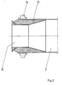
- Eine weitere vorteilhafte Ausgestaltung des Drehrohres der eingangs beschriebenen Art besteht darin, daß die auf Rollen laufenden Laufringe 14 durch einen zwischen Drehrohr 2 und einem Drehrohreinzug 15 angebrachte Isolierung 16 von dem Drehrohrmantel 2 thermisch isoliert sind. Die Darstellung in Figur 2 zeigt beispielhaft eine derartige Anordnung.
- Zum Abräumen bzw. Lockern sich beim Betrieb im Drehrohr etwa bildender Krusten, Koksablagerungen o. dgl. können innenliegende, an der drehenden Wandung abrollende schwere längszylindrische Wälzkörper vorgesehen werden. Durch in Längsrichtung an dem Wälzkörper verlaufende Rippen, Nuten oder Hinterschneidungen kann die angestrebte Wirkung je nach den Erfordernissen der durchgesetzten Materialien unterstützt werden.
Claims (5)
Applications Claiming Priority (2)
| Application Number | Priority Date | Filing Date | Title |
|---|---|---|---|
| DE3830678A DE3830678A1 (de) | 1988-09-09 | 1988-09-09 | Drehrohr |
| DE3830678 | 1988-09-09 |
Publications (3)
| Publication Number | Publication Date |
|---|---|
| EP0357939A2 true EP0357939A2 (de) | 1990-03-14 |
| EP0357939A3 EP0357939A3 (de) | 1991-01-09 |
| EP0357939B1 EP0357939B1 (de) | 1994-07-06 |
Family
ID=6362610
Family Applications (1)
| Application Number | Title | Priority Date | Filing Date |
|---|---|---|---|
| EP89113941A Expired - Lifetime EP0357939B1 (de) | 1988-09-09 | 1989-07-28 | Drehrohr |
Country Status (9)
| Country | Link |
|---|---|
| US (1) | US5022852A (de) |
| EP (1) | EP0357939B1 (de) |
| JP (1) | JPH02113088A (de) |
| AT (1) | ATE108267T1 (de) |
| CA (1) | CA1326357C (de) |
| DD (1) | DD287767A5 (de) |
| DE (3) | DE3830678A1 (de) |
| ES (1) | ES2056157T3 (de) |
| RU (1) | RU2037509C1 (de) |
Cited By (5)
| Publication number | Priority date | Publication date | Assignee | Title |
|---|---|---|---|---|
| AT397861B (de) * | 1990-09-04 | 1994-07-25 | Ragailler Roland Mag | Drehofen, insbesondere zur pyrolyse von abfallprodukten |
| AU658083B2 (en) * | 1991-03-13 | 1995-03-30 | Kawasaki Steel Corporation | Apparatus for the manufacture of tinplates |
| EP0813035A1 (de) * | 1996-06-13 | 1997-12-17 | Noell-KRC Energie- und Umwelttechnik GmbH | Dichtung für Drehrohre |
| US5707592A (en) * | 1991-07-18 | 1998-01-13 | Someus; Edward | Method and apparatus for treatment of waste materials including nuclear contaminated materials |
| EP4361545A1 (de) * | 2022-10-25 | 2024-05-01 | ThyssenKrupp Steel Europe AG | Anlagenverbund und verfahren zum herstellen von roheisen |
Families Citing this family (10)
| Publication number | Priority date | Publication date | Assignee | Title |
|---|---|---|---|---|
| AT398389B (de) * | 1992-11-06 | 1994-11-25 | Andritz Patentverwaltung | Verfahren und anlage zur trennung von feststoff-flüssigkeit-mischungen |
| US6558157B1 (en) * | 2000-11-13 | 2003-05-06 | Veba Oel Technologie Und Automatisierung Gmbh | Rotary drum with rolling body arrangement |
| DE20019275U1 (de) * | 2000-11-13 | 2002-03-28 | VEBA OEL Technologie und Automatisierung GmbH, 45879 Gelsenkirchen | Drehtrommel mit Wälzkörperanordnung |
| DE102018133566A1 (de) | 2018-12-21 | 2020-06-25 | Eisenmann Se | Drehrohrofen |
| EP4587771A1 (de) * | 2022-09-16 | 2025-07-23 | thyssenkrupp Polysius GmbH | Dichtung für einen drehrohrofen |
| LU103007B1 (de) * | 2022-09-16 | 2024-03-18 | Thyssenkrupp Ag | Dichtung für einen Drehrohrofen |
| DE102023125357A1 (de) * | 2023-09-19 | 2025-03-20 | Eagleburgmann Germany Gmbh & Co. Kg | Drehrohrofendichtungsanordnung |
| DE102023125398A1 (de) * | 2023-09-19 | 2025-03-20 | Eagleburgmann Germany Gmbh & Co. Kg | Drehrohrofendichtsystem mit Kühlanordnung |
| DE102023125340A1 (de) * | 2023-09-19 | 2025-03-20 | Eagleburgmann Germany Gmbh & Co. Kg | Drehrohrofendichtsystem mit Ausgleichsanordnung |
| EP4571228A1 (de) * | 2023-12-15 | 2025-06-18 | ThyssenKrupp Steel Europe AG | Verfahren zur gewinnung eines schwammprodukts mit hohem metallisierungsgrad |
Family Cites Families (13)
| Publication number | Priority date | Publication date | Assignee | Title |
|---|---|---|---|---|
| FR905278A (fr) * | 1944-06-20 | 1945-11-29 | Azote & Prod Chim | Perfectionnements aux dispositifs d'étanchéité pour fours rotatifs et appareils analogues |
| DE1202207B (de) * | 1964-04-16 | 1965-09-30 | Beteiligungs & Patentverw Gmbh | Vorrichtung zur Abdichtung der feststehenden gegen die beweglichen Teile eines Drehrohrofens |
| DE1783016B1 (de) * | 1968-09-19 | 1970-08-27 | Polysius Ag | Drehtrommel |
| FR2049595A5 (de) * | 1969-06-13 | 1971-03-26 | Metallgesellschaft Ag | |
| BE771649A (fr) * | 1970-09-09 | 1971-12-31 | Fives Lille Cail | Four ou echangeur de chaleur tubulaire et rotatif comportant aumoins une zone renforcee par une structure annulaire |
| US3724887A (en) * | 1971-05-18 | 1973-04-03 | Treadwell Corp | Kiln seal |
| DE2263220C3 (de) * | 1972-12-23 | 1975-12-11 | Buettner-Schilde-Haas Ag, 4150 Krefeld | Stopfbuchse zum Abdichten eines Gut- oder Heizmittetzu- oder -abführrohres bei Drehtrommeln |
| US4183726A (en) * | 1978-04-13 | 1980-01-15 | Seebald John W | Pyro-processing rotary kiln mixing rod |
| DE3008741C2 (de) * | 1980-03-07 | 1982-10-21 | Buckau-Walther AG, 4048 Grevenbroich | Vorrichtung für die Pyrolyse von Müll |
| DE3114695A1 (de) * | 1981-04-10 | 1982-10-28 | Krupp Polysius Ag, 4720 Beckum | Vorrichtung zur abdichtung des spaltes zwischen drehrohrofen und einlaufgehaeuse |
| DE3320767A1 (de) * | 1983-06-09 | 1984-12-13 | Elino Industrie-Ofenbau Carl Hanf GmbH + Co, 5160 Düren | Dichtungseinrichtung fuer oefen |
| DE3407236A1 (de) * | 1984-02-28 | 1985-09-12 | Environment Protecting Engineers, Inc., Southfield, Mich. | Verfahren zur herstellung hochwertiger brennstoffe, drehtrommelreaktor zur durchfuehrung des verfahrens und verwendung des drehtrommelreaktors |
| DE3777520D1 (de) * | 1986-09-30 | 1992-04-23 | Nihon Cement | Rotierender ofen. |
-
1988
- 1988-09-09 DE DE3830678A patent/DE3830678A1/de active Granted
-
1989
- 1989-03-18 DE DE8903410U patent/DE8903410U1/de not_active Expired - Lifetime
- 1989-07-28 AT AT89113941T patent/ATE108267T1/de not_active IP Right Cessation
- 1989-07-28 ES ES89113941T patent/ES2056157T3/es not_active Expired - Lifetime
- 1989-07-28 DE DE58908002T patent/DE58908002D1/de not_active Expired - Lifetime
- 1989-07-28 EP EP89113941A patent/EP0357939B1/de not_active Expired - Lifetime
- 1989-09-07 DD DD89332434A patent/DD287767A5/de not_active IP Right Cessation
- 1989-09-08 JP JP1231822A patent/JPH02113088A/ja active Pending
- 1989-09-08 RU SU894614892A patent/RU2037509C1/ru not_active IP Right Cessation
- 1989-09-08 CA CA000610756A patent/CA1326357C/en not_active Expired - Lifetime
- 1989-09-11 US US07/405,231 patent/US5022852A/en not_active Expired - Lifetime
Cited By (6)
| Publication number | Priority date | Publication date | Assignee | Title |
|---|---|---|---|---|
| AT397861B (de) * | 1990-09-04 | 1994-07-25 | Ragailler Roland Mag | Drehofen, insbesondere zur pyrolyse von abfallprodukten |
| AU658083B2 (en) * | 1991-03-13 | 1995-03-30 | Kawasaki Steel Corporation | Apparatus for the manufacture of tinplates |
| US5707592A (en) * | 1991-07-18 | 1998-01-13 | Someus; Edward | Method and apparatus for treatment of waste materials including nuclear contaminated materials |
| EP0813035A1 (de) * | 1996-06-13 | 1997-12-17 | Noell-KRC Energie- und Umwelttechnik GmbH | Dichtung für Drehrohre |
| US6003874A (en) * | 1996-06-13 | 1999-12-21 | Noell-Krc Energie-Und Umwelttechnik Gmbh | Apparatus for sealing rotary tubes |
| EP4361545A1 (de) * | 2022-10-25 | 2024-05-01 | ThyssenKrupp Steel Europe AG | Anlagenverbund und verfahren zum herstellen von roheisen |
Also Published As
| Publication number | Publication date |
|---|---|
| CA1326357C (en) | 1994-01-25 |
| RU2037509C1 (ru) | 1995-06-19 |
| US5022852A (en) | 1991-06-11 |
| DD287767A5 (de) | 1991-03-07 |
| ES2056157T3 (es) | 1994-10-01 |
| DE8903410U1 (de) | 1990-01-04 |
| EP0357939A3 (de) | 1991-01-09 |
| JPH02113088A (ja) | 1990-04-25 |
| DE3830678A1 (de) | 1990-03-22 |
| DE58908002D1 (de) | 1994-08-11 |
| DE3830678C2 (de) | 1991-05-08 |
| ATE108267T1 (de) | 1994-07-15 |
| EP0357939B1 (de) | 1994-07-06 |
Similar Documents
| Publication | Publication Date | Title |
|---|---|---|
| EP0357939B1 (de) | Drehrohr | |
| DE2556601B2 (de) | Drehrohrofen-Abdichtvorrichtung | |
| DE3610490A1 (de) | Foerderschnecke, insbesondere zum chargieren eines ofens | |
| DE102018133566A1 (de) | Drehrohrofen | |
| DE3741112A1 (de) | Verbesserte anlage zum pyrolisieren und/oder trocknen von biologischem schlamm oder dergleichen | |
| DE3342572C2 (de) | ||
| DE3346338A1 (de) | Rotierende schweltrommel zum verschwelen von abfallstoffen | |
| DE2641042A1 (de) | Einrichtung zur entnahme von gasproben aus oefen, insbesondere aus hochoefen | |
| CH661341A5 (de) | Drehrohrofen. | |
| DE3702318C1 (en) | Rotary drum for the carbonisation of wastes with exclusion of air | |
| EP0813035B1 (de) | Dichtung für Drehrohre | |
| DE3312599A1 (de) | Russblaeser zum beseitigen von ablagerungen in gasdurchstroemten raeumen, wie waermetauschern, reaktionsraeumen und dergleichen | |
| DE4011945C1 (en) | Waste material pyrolysis system - compresses material and heats it by friction against chamber walls | |
| DE3320767C2 (de) | ||
| DE2417222C2 (de) | Einrichtung zum Abdichten und Richten von beweglichen Meßsonden an Schachtofen, insbesondere an Hochöfen | |
| DE2001006A1 (de) | Glockenofen | |
| DE2138924B2 (de) | Druckgefäß für Atomkernreaktoren | |
| DE3605756C2 (de) | ||
| CH673467A5 (de) | ||
| DE622472C (de) | Vorrichtung zur Destillation von Metallen | |
| DE3844684A1 (de) | Drehrohr | |
| AT92552B (de) | Drehretorte zum ununterbrochenen Schwelen. | |
| DE2424868C3 (de) | Lagerung des Ofenkopfes eines Drehrohrofens | |
| DE1802361C (de) | Abdichtvornchtung zwischen einem fest stehenden Gehäuse und dem Ein und/oder Aus laßende eines Drehrohres | |
| DE547457C (de) | Verfahren zur Destillation und Spaltung von festen, fluessigen und gasfoermigen Stoffen, insbesondere von Kohlenwasserstoffoelen |
Legal Events
| Date | Code | Title | Description |
|---|---|---|---|
| PUAI | Public reference made under article 153(3) epc to a published international application that has entered the european phase |
Free format text: ORIGINAL CODE: 0009012 |
|
| 17P | Request for examination filed |
Effective date: 19890808 |
|
| AK | Designated contracting states |
Kind code of ref document: A2 Designated state(s): AT BE CH DE ES FR GB GR IT LI LU NL SE |
|
| RAP1 | Party data changed (applicant data changed or rights of an application transferred) |
Owner name: VEBA OEL TECHNOLOGIE GMBH |
|
| PUAL | Search report despatched |
Free format text: ORIGINAL CODE: 0009013 |
|
| AK | Designated contracting states |
Kind code of ref document: A3 Designated state(s): AT BE CH DE ES FR GB GR IT LI LU NL SE |
|
| 17Q | First examination report despatched |
Effective date: 19920630 |
|
| RAP1 | Party data changed (applicant data changed or rights of an application transferred) |
Owner name: VEBA OEL TECHNOLOGIE UND AUTOMATISIERUNG GMBH |
|
| GRAA | (expected) grant |
Free format text: ORIGINAL CODE: 0009210 |
|
| AK | Designated contracting states |
Kind code of ref document: B1 Designated state(s): AT BE CH DE ES FR GB GR IT LI LU NL SE |
|
| REF | Corresponds to: |
Ref document number: 108267 Country of ref document: AT Date of ref document: 19940715 Kind code of ref document: T |
|
| ET | Fr: translation filed | ||
| REF | Corresponds to: |
Ref document number: 58908002 Country of ref document: DE Date of ref document: 19940811 |
|
| REG | Reference to a national code |
Ref country code: CH Ref legal event code: PK |
|
| RIN2 | Information on inventor provided after grant (corrected) |
Free format text: WENNING, HANS-PETER * BLASKO, MICHAEL * VITS, REINHARD |
|
| ITF | It: translation for a ep patent filed | ||
| REG | Reference to a national code |
Ref country code: ES Ref legal event code: FG2A Ref document number: 2056157 Country of ref document: ES Kind code of ref document: T3 |
|
| EPTA | Lu: last paid annual fee | ||
| GBT | Gb: translation of ep patent filed (gb section 77(6)(a)/1977) |
Effective date: 19940912 |
|
| REG | Reference to a national code |
Ref country code: GR Ref legal event code: FG4A Free format text: 3012990 |
|
| EAL | Se: european patent in force in sweden |
Ref document number: 89113941.2 |
|
| PLBE | No opposition filed within time limit |
Free format text: ORIGINAL CODE: 0009261 |
|
| STAA | Information on the status of an ep patent application or granted ep patent |
Free format text: STATUS: NO OPPOSITION FILED WITHIN TIME LIMIT |
|
| 26N | No opposition filed | ||
| REG | Reference to a national code |
Ref country code: GB Ref legal event code: IF02 |
|
| PGFP | Annual fee paid to national office [announced via postgrant information from national office to epo] |
Ref country code: GR Payment date: 20040430 Year of fee payment: 16 |
|
| PGFP | Annual fee paid to national office [announced via postgrant information from national office to epo] |
Ref country code: ES Payment date: 20040507 Year of fee payment: 16 |
|
| PGFP | Annual fee paid to national office [announced via postgrant information from national office to epo] |
Ref country code: BE Payment date: 20040510 Year of fee payment: 16 |
|
| PGFP | Annual fee paid to national office [announced via postgrant information from national office to epo] |
Ref country code: SE Payment date: 20040611 Year of fee payment: 16 |
|
| PGFP | Annual fee paid to national office [announced via postgrant information from national office to epo] |
Ref country code: LU Payment date: 20040622 Year of fee payment: 16 |
|
| PGFP | Annual fee paid to national office [announced via postgrant information from national office to epo] |
Ref country code: CH Payment date: 20040720 Year of fee payment: 16 |
|
| PGFP | Annual fee paid to national office [announced via postgrant information from national office to epo] |
Ref country code: NL Payment date: 20040731 Year of fee payment: 16 |
|
| PG25 | Lapsed in a contracting state [announced via postgrant information from national office to epo] |
Ref country code: LU Free format text: LAPSE BECAUSE OF NON-PAYMENT OF DUE FEES Effective date: 20050728 |
|
| PG25 | Lapsed in a contracting state [announced via postgrant information from national office to epo] |
Ref country code: SE Free format text: LAPSE BECAUSE OF NON-PAYMENT OF DUE FEES Effective date: 20050729 Ref country code: ES Free format text: LAPSE BECAUSE OF NON-PAYMENT OF DUE FEES Effective date: 20050729 |
|
| PG25 | Lapsed in a contracting state [announced via postgrant information from national office to epo] |
Ref country code: LI Free format text: LAPSE BECAUSE OF NON-PAYMENT OF DUE FEES Effective date: 20050731 Ref country code: CH Free format text: LAPSE BECAUSE OF NON-PAYMENT OF DUE FEES Effective date: 20050731 Ref country code: BE Free format text: LAPSE BECAUSE OF NON-PAYMENT OF DUE FEES Effective date: 20050731 |
|
| PG25 | Lapsed in a contracting state [announced via postgrant information from national office to epo] |
Ref country code: NL Free format text: LAPSE BECAUSE OF NON-PAYMENT OF DUE FEES Effective date: 20060201 |
|
| PG25 | Lapsed in a contracting state [announced via postgrant information from national office to epo] |
Ref country code: GR Free format text: LAPSE BECAUSE OF NON-PAYMENT OF DUE FEES Effective date: 20060202 |
|
| REG | Reference to a national code |
Ref country code: CH Ref legal event code: PL |
|
| EUG | Se: european patent has lapsed | ||
| NLV4 | Nl: lapsed or anulled due to non-payment of the annual fee |
Effective date: 20060201 |
|
| REG | Reference to a national code |
Ref country code: ES Ref legal event code: FD2A Effective date: 20050729 |
|
| BERE | Be: lapsed |
Owner name: *VEBA OEL TECHNOLOGIE UND AUTOMATISIERUNG G.M.B.H. Effective date: 20050731 |
|
| PGFP | Annual fee paid to national office [announced via postgrant information from national office to epo] |
Ref country code: DE Payment date: 20080626 Year of fee payment: 20 |
|
| PGFP | Annual fee paid to national office [announced via postgrant information from national office to epo] |
Ref country code: AT Payment date: 20080618 Year of fee payment: 20 Ref country code: FR Payment date: 20080728 Year of fee payment: 20 Ref country code: IT Payment date: 20080730 Year of fee payment: 20 |
|
| PGFP | Annual fee paid to national office [announced via postgrant information from national office to epo] |
Ref country code: GB Payment date: 20080806 Year of fee payment: 20 |
|
| REG | Reference to a national code |
Ref country code: GB Ref legal event code: PE20 Expiry date: 20090727 |
|
| PG25 | Lapsed in a contracting state [announced via postgrant information from national office to epo] |
Ref country code: GB Free format text: LAPSE BECAUSE OF EXPIRATION OF PROTECTION Effective date: 20090727 |