EP0358064A1 - Procédé de préparation de particules très fines très pures de métaux réactifs et récipient de préparation - Google Patents
Procédé de préparation de particules très fines très pures de métaux réactifs et récipient de préparation Download PDFInfo
- Publication number
- EP0358064A1 EP0358064A1 EP89115749A EP89115749A EP0358064A1 EP 0358064 A1 EP0358064 A1 EP 0358064A1 EP 89115749 A EP89115749 A EP 89115749A EP 89115749 A EP89115749 A EP 89115749A EP 0358064 A1 EP0358064 A1 EP 0358064A1
- Authority
- EP
- European Patent Office
- Prior art keywords
- vessel
- inert gas
- gas atmosphere
- moisture
- reactive metals
- Prior art date
- Legal status (The legal status is an assumption and is not a legal conclusion. Google has not performed a legal analysis and makes no representation as to the accuracy of the status listed.)
- Granted
Links
Images


Classifications
-
- B—PERFORMING OPERATIONS; TRANSPORTING
- B22—CASTING; POWDER METALLURGY
- B22F—WORKING METALLIC POWDER; MANUFACTURE OF ARTICLES FROM METALLIC POWDER; MAKING METALLIC POWDER; APPARATUS OR DEVICES SPECIALLY ADAPTED FOR METALLIC POWDER
- B22F9/00—Making metallic powder or suspensions thereof
- B22F9/02—Making metallic powder or suspensions thereof using physical processes
- B22F9/04—Making metallic powder or suspensions thereof using physical processes starting from solid material, e.g. by crushing, grinding or milling
-
- C—CHEMISTRY; METALLURGY
- C01—INORGANIC CHEMISTRY
- C01B—NON-METALLIC ELEMENTS; COMPOUNDS THEREOF; METALLOIDS OR COMPOUNDS THEREOF NOT COVERED BY SUBCLASS C01C
- C01B32/00—Carbon; Compounds thereof
- C01B32/90—Carbides
- C01B32/914—Carbides of single elements
-
- Y—GENERAL TAGGING OF NEW TECHNOLOGICAL DEVELOPMENTS; GENERAL TAGGING OF CROSS-SECTIONAL TECHNOLOGIES SPANNING OVER SEVERAL SECTIONS OF THE IPC; TECHNICAL SUBJECTS COVERED BY FORMER USPC CROSS-REFERENCE ART COLLECTIONS [XRACs] AND DIGESTS
- Y10—TECHNICAL SUBJECTS COVERED BY FORMER USPC
- Y10S—TECHNICAL SUBJECTS COVERED BY FORMER USPC CROSS-REFERENCE ART COLLECTIONS [XRACs] AND DIGESTS
- Y10S241/00—Solid material comminution or disintegration
- Y10S241/14—Grinding in inert, controlled atmosphere
-
- Y—GENERAL TAGGING OF NEW TECHNOLOGICAL DEVELOPMENTS; GENERAL TAGGING OF CROSS-SECTIONAL TECHNOLOGIES SPANNING OVER SEVERAL SECTIONS OF THE IPC; TECHNICAL SUBJECTS COVERED BY FORMER USPC CROSS-REFERENCE ART COLLECTIONS [XRACs] AND DIGESTS
- Y10—TECHNICAL SUBJECTS COVERED BY FORMER USPC
- Y10S—TECHNICAL SUBJECTS COVERED BY FORMER USPC CROSS-REFERENCE ART COLLECTIONS [XRACs] AND DIGESTS
- Y10S505/00—Superconductor technology: apparatus, material, process
- Y10S505/825—Apparatus per se, device per se, or process of making or operating same
- Y10S505/888—Refrigeration
- Y10S505/894—Cyclic cryogenic system, e.g. sterling, gifford-mcmahon
Definitions
- the present invention generally relates to a method of making high-purity fine particles of reactive metals and a manufacturing vessel therefor, and relates more particularly to a method of making high-purity fine particles of reactive metals of IIa, IIIa, IVa, and IVb families in the periodical table and a manufacturing vessel therefor, which reactive metals are apt to form hydroxides such as Sr, Ba, and Y that are the elements fundamental to the production of superconducting materials, and Hf that is appreciated for its high hardness and thermal resistance.
- a currently popular method of making superconducting materials which are compounded oxides of Sr, Ba, Y, La, Cu, and other elements, is to use salts or oxides of these metals for raw materials.
- carbide of metallic Hf obtained in hydrogen-reducing Hf salts is used.
- the complexity of the reaction system is due to a multitude of manufacturing steps calling for large investment in equipment and high manufacturing costs in mass production.
- the primary purpose of this invention is to therefore provide a method of manufacturing high-purity fine particles of reactive metals and a manufacturing vessel therefor, the metals being reactive especially in terms of liability to form hydroxides, namely elements of IIa, IIIa, IVa, and IVb families in the periodical table (these metals will be called "reactive metals” hereinafter).
- the method and the vessel of the present invention are described in several embodiments.
- metallic Na is solid gettering, owing to which, the remaining moisture can be reduced to an extremely low level, e.g., 10-100 Weight/volume part per billion (109) (W/V ppb.).
- a third embodiment we offer a method for pulverizing any reactive metals of IIa, IIIa, IVa, and IVb families in the periodical table. That is to say, even though this method is adaptable to the so-called reactive metals in general, the third embodiment is particularly useful for making high-purity fine particles out of the kind of metals which are liable to form hydroxides.
- a first embodiment of the manufacturing vessel is a hermetically sealable vessel, which is equipped with a pair (or a number of pairs) of rubber gloves of the type that allow an operator standing outside the vessel to freely manipulate objects placed under an inert gas atmosphere inside the vessel, namely, those that are often employed in a so-called “glove box”, which is further equipped with a device for cryogenically cooling the moisture into dew droplets at a vessel inner wall and an accumulator which functions to adapt the vessel's internal pressure to the ambient pressure.
- the dew droplets formed on an inner wall of the vessel are removed by means of a trapping technique, for which we have separately filed a patent application with the Japanese Patent Office, entitled “Method of Removing Moisture Remaining in an Atmosphere Gas” (Japanese Patent Application No. 63-192037 filed August 2, 1988).
- metallic Na is employed as the solid getter agent to absorb the moisture in the form of sodium hydroxide.
- a manufacturing vessel is provided that is equipped with a plurality of glove boxes mutually connected in series.
- the series of operations can be performed by an individual stage, each stage in an appropriate box, but in line as a whole.
- a covering door over each glove opening and a device to adapt the pressure in the space made by the covering door and glove to the internal pressure of the vessel. Due to this construction, the pressure in the space made by the covering door and glove is held always equal to that inside the vessel even when the latter is evacuated or filled with an inert gas, thus preventing the gloves from getting damaged as the atmospheric conditions of the manufacturing vessel are altered.
- the present invention provides a method of making high-purity fine particles of reactive metals that are liable to form hydroxides, i.e., the metals of IIa, IIIa, IVa, and IVb families in the periodical table, in four embodiments, and three embodiments of a vessel for making such particles in which particularly the second embodiment provides the feasibility of performing operations in line but an independent operation in each box, and the third embodiment features freely changing vessel atmosphere without damaging the rubber gloves.
- Figures 1 to 3 present a vessel l for manufacturing high-purity fine particles of reactive metals in the form of one embodiment of this invention, wherein vessel 1 comprises three hermetically sealable vessels 2a,2b, and 2c, connected in series.
- vessel 1 comprises three hermetically sealable vessels 2a,2b, and 2c, connected in series.
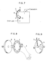
- a pair of rubber gloves 3 each of which is hermetically attached to the vessel by a guide ring 4, as shown in Figures 7 and 8, so that the operator may perform operations freely within the vessel without affecting the inert gas atmosphere inside the vessel.
- a covering door 5 is pivotably mounted on the vessel's side wall so as to close the opening defined by the glove 8.
- the door 5 fits onto an O-ring 6, as shown in Figures 7 and 8.
- a pressure adapting device 7, comprising a pressure hose 8 which connects the inner space of the glove 3, now covered with the covering door 5, to the interior of vessels 2a,2b or 2c, so as to hold the respective pressures equal, and an electromagnetic valve 9 which is provided at an uptake port of each vessel.
- an observation window 10 is provided above each pair of the glove openings 3 so as to allow free surveillance of the vessel interior.
- the evacuation line 14 is provided with a vacuum gauge 15, a main valve 16, and an exhaust valve 17 in that order, and is branched at the flanges 22 between the vacuum gauge 15 and the main valve 16.
- Each flange 22 possesses an O-ring.
- the branch or a pressure regulation line 18 is connected to an accumulator 20 at an O-ring flange 23.
- the pressure regulation line 18 is equipped with an electromagnetic valve 19 which is switched into an open position when the foot pedal 21 is depressed.
- the accumulator 20 which functions to adapt the vessel internal pressure to the ambient atmospheric pressure, includes a backflow absorber 24, ending in a high-pressure mesh vinyl hose 25, a glass bottle 26, and an oil bath (kerosene) 27 with the hose 25 ending within the oil bath 27.
- each of the vessels 2a,2b, and 2c is provided with an inert gas inlet port 28 at its front lower part as shown in Figure l, and is further provided with a cryogenic dew condenser 29 at its back wall as shown in Figure 2.
- the cryogenic dew condenser 29 includes a dew condensing plate 30 that forms a part of the vessel's back wall, a cryogenic cooling box 31 that contains the cryogenic cooling medium so as to cool the dew condensing plate 30, a funnel-shaped pouring port 32 through which the cryogenic cooling medium is supplied into the cooling box 31, and an automatic temperature controller 33 that regulates the cooling temperature, e.g., by means of a heat pipe, where the dew condensing plate 30 is integrally attached to the vessel's back wall by means of a double seal 34.
- both the dew condensing plate 30 and the cooling box 31 (box 31 being integrally formed with the plate 30) are made from copper and are covered with a thermal insulator 35.
- the vessels 2a,2b, and 2c are respectively provided with lamps 36 at their ceilings and are further equipped with an operation panel 37 on the front side, a power inlet terminal 38 at the back side ( Figure 3), and a drain port 39 at the bottom.
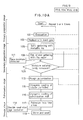
- the method according to this invention comprises a primary preparation stage, a secondary preparation stage, a pulverization stage, and a product storage stage.
- the primary preparation stage we completely replace the inner atmosphere of the vessel 1 with an inert gas.
- we evacuate the vessels 2a, 2b, and 2c step 101) by means of a vacuum pump 13 through the evacuation line 14 by operating the main valve 16 and the exhaust valve 17 appropriately.
- the inert gas is supplied to the vessels 2a,2b, and 2c through the inert gas inlet port 28 (step 102).
- This evacuation (step 101) plus replacement (step 102) operation is repeated three or four times, during which we make use of the accumulator 20 of the pressure regulation line 18 so as to maintain the inert gas pressure of the vessel inner atmosphere equal to the ambient atmospheric pressure by appropriately activating the electromagnetic valve 19 by the foot pedal 22.
- step 101 we take care to keep the situations inside the vessels 2a,2b, and 2c under close observation through respective observation windows 10, to keep the covering doors 5 closed over the glove openings 3, and to activate the respective pressure equalizing devices 7 of the doors 5 so as to protect the gloves 3 by holding the pressure in the space made by the gloves and doors 5 equal to that in the vessels 2a,2b, and 2c.
- the gloves 3 allow the operator to insert his hands into the vessels without affecting the sealing of the vessels.
- step 107 we remove this moisture to an extremely low content level.
- step 107 we have disclosed in a separate patent application filed in Japan (Japanese Patent Application No. 63-183672 filed July 25, 1988). Essentially, this is done by the solid gettering method. Namely, we supply a cryogenic cooling medium to each of the dew condensers 29 provided in the vessels 2a, 2b, and 2c through their pouring ports 32.
- the dew condensing plates 30 are cooled to -150 degress C (°C) or even below, whereupon the moisture remaining in the atmosphere gas is condensed into dew droplets (practically forming ice-flakes) on the walls of the vessels 2a, 2b, and 2c.
- the Na vapor thus generated fills up the interior of vessel 1 to react with the moisture present in the vessel atmosphere in a reaction known as gas phase getter. 2 ⁇ Na + 2 ⁇ H2O ⁇ 2 ⁇ NaOH + H2, whereby the remaining moisture is reduced (step 106) to an extremely low content level, e.g., between 10 and 100 W/V ppb.
- this method (step 110) utilizes a phenomenon wherein, when a dark barium powder comes into contact with moisture, it gets bleached.
- the detector 111 includes a transparent cylinder to permit free observation of the content's color with an appropriate quantity of dark barium powder being placed in the transparent cylinder, a pair of gas-permeable stoppers that keep the dark barium powder within the cylinder while allowing the atmosphere gas to come into contact with the barium powder, and a pair of removable covers provided at either end of the transparent cylinder and fixed thereto with a sealant to prevent untimely intrusion of the atmosphere gas.
- step 109 Dark barium powder functions as a moisture indicator 112. We repeat the gas phase gettering operation until the remaining moisture content has been proven to reach the desired level (step 109),e.g., between 10 and 100 W/V ppb.
- step 113 we immerse the coarsest particles thus produced in a cryogenic cooling medium, such as liquified nitrogen, so as to cool them to a temperature of -150°C or even lower (step 115) and to decrease their ductility at the same time.
- a pulverization mill which may be a vibration rod mill or a ball mill, for mechanical pulverization operation by cooling it, especially its vibrator or balls, if necessary to a cryogenic temperature, say -150°C or lower (step 116).
- step 117 we pulverize the coarse reactive metal particles in the mill thus prepared to fine particles (step 117), e.g., 5 micrometers or even smaller in size.
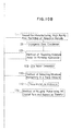
- step 113 For rough pulverization (step 113) of Hf crystal bars, in particular, we prefer to use the apparatus (step 114) which we disclose in the Japanese Patent Application No. 63-238989 filed on September 26, 1988 entitled "Method of Roughly Pulverizing Hf Crystal Bars and Apparatus Therefor".
- the storage container 118 is preferably of a double-seal construction so as to ensure perfect hermeticity against contamination by oxygen and moisture of the environmental air.
- the vessel 1 does not have to comprise three glove boxes mutually connected in series; namely, all the four stages of manufacturing can be performed in a single vessel, or, alternatively, each stage can be assigned to a different and independent vessel of a four-vessel hermetic train.
- a fine particle manufacturing hermetic vessel such as described above can be a module in a group of various work modules, such as raw materials preparation modules, materials pulverization modules, conveyor modules (that take care of transfer of semiproducts, products, pulverization mills and such), powder mixing modules, powder metallurgical press forming modules, sintering furnace modules, weighing and packing modules and the like, to be put to service in an appropriate combination with any other modules.
- various work modules such as raw materials preparation modules, materials pulverization modules, conveyor modules (that take care of transfer of semiproducts, products, pulverization mills and such), powder mixing modules, powder metallurgical press forming modules, sintering furnace modules, weighing and packing modules and the like, to be put to service in an appropriate combination with any other modules.
- step 101 and 102 in establishing an inert gas atmosphere within the manufacturing vessel 1, by performing the solid gettering and, if needed, the gas phase gettering with metallic Na, to achieve an extremely low level of moisture content, e.g., 10 to 100 W/V ppb, by devising a novel method of confirming the atmosphere's having attained this level, by conducting pulverization operations at a cryogenic temperature, e.g., -150°C or even lower, and by collecting and sealing the product particles in a double-seal container under the same atmosphere.
- a cryogenic temperature e.g., -150°C or even lower
- the secondary preparation stage wherein we achieve an extremely low level of moisture content, e.g., between 10 and 100 W/V ppb.
- a cryogenic dew condenser 29 with the vessel 1 (comprising vessels 2a, 2b, and 2c in the embodiment described earlier) and let the moisture in the inert gas atmosphere condense into dew droplets on inner walls of the vessel 1; on these dew droplets we perform the solid gettering by bringing a piece of metallic Na into contact with them, resulting in dissociation and removal of moisture as a hydroxide group (step 105); subsequently, we remove the moisture still in the atmosphere by performing the gas phase gettering through generating Na vapor with a Na vapor generator 108 in the vessel 1, again resulting in dissociation and removal of moisture as a hydroxide group (step 105) and attaining the extremely low-level moisture content, e.g., between 10 and 100 W/V ppb.
- the product of this invention is not a compound but a high-purity metal, it can be processed through much simpler reaction systems into desired complex metallic oxides, which finish with atomic structures of high regularity. Also, the disuse of metallic compounds for the starters results in extremely rare intrusion of impurity atoms or presence of voids in the crystalline structure, because no undesired substances are formed through dissociation during processing. This is reflected by the good reproducibility and stability of quality and performances.
- the HfC made from Hf metal produced by this invention method is characterized by markedly higher purity as mentioned above. This means that the Hf metal produced by this invention method is better adapted to make complex carbides together with W, Ta, Nb, Mo, Co, and others for the purpose of improving the elastic properties over that of simple HfC.
- the method of the present invention will prove to be more advantageous because it enables the construction of a mass production line at less equipment investment than that required for modifying the currently popular methods of producing HfC, because the latter are basically a throughput process leading to HfC, or those of producing powder metallic Hf out of sponge Hf, because the metallic Hf they produce inevitably contains impurities such as nitrogen, oxygen, chlorine, and magnesium.
Landscapes
- Chemical & Material Sciences (AREA)
- Organic Chemistry (AREA)
- Inorganic Chemistry (AREA)
- Manufacture Of Metal Powder And Suspensions Thereof (AREA)
- Physical Or Chemical Processes And Apparatus (AREA)
- Drying Of Gases (AREA)
Applications Claiming Priority (4)
| Application Number | Priority Date | Filing Date | Title |
|---|---|---|---|
| JP63210620A JPH0729067B2 (ja) | 1988-08-26 | 1988-08-26 | 活性金属の高純度微粉末製造方法 |
| JP210620/88 | 1988-08-26 | ||
| JP63218486A JPH0774361B2 (ja) | 1988-09-02 | 1988-09-02 | 活性金属の高純度微粉末製造装置 |
| JP218486/88 | 1988-09-02 |
Publications (2)
| Publication Number | Publication Date |
|---|---|
| EP0358064A1 true EP0358064A1 (fr) | 1990-03-14 |
| EP0358064B1 EP0358064B1 (fr) | 1993-08-04 |
Family
ID=26518161
Family Applications (1)
| Application Number | Title | Priority Date | Filing Date |
|---|---|---|---|
| EP89115749A Expired - Lifetime EP0358064B1 (fr) | 1988-08-26 | 1989-08-25 | Procédé de préparation de particules très fines très pures de métaux réactifs et récipient de préparation |
Country Status (3)
| Country | Link |
|---|---|
| US (2) | US4971258A (fr) |
| EP (1) | EP0358064B1 (fr) |
| DE (1) | DE68908048T2 (fr) |
Families Citing this family (17)
| Publication number | Priority date | Publication date | Assignee | Title |
|---|---|---|---|---|
| US5545396A (en) | 1994-04-08 | 1996-08-13 | The Research Foundation Of State University Of New York | Magnetic resonance imaging using hyperpolarized noble gases |
| US5809801A (en) * | 1996-03-29 | 1998-09-22 | The Trustees Of Princeton University | Cryogenic accumulator for spin-polarized xenon-129 |
| US5642625A (en) * | 1996-03-29 | 1997-07-01 | The Trustees Of Princeton University | High volume hyperpolarizer for spin-polarized noble gas |
| US6085743A (en) * | 1997-05-30 | 2000-07-11 | The Regent Of The University Of Michigan | Polarized gas delivery system/method |
| ATE366134T1 (de) | 1997-08-18 | 2007-07-15 | Univ Princeton | Spin-polarisation eines edelgases über spinaustausch mit optisch gepumpten alkalimetallen |
| US6079213A (en) * | 1997-12-12 | 2000-06-27 | Magnetic Imaging Technologies Incorporated | Methods of collecting, thawing, and extending the useful life of polarized gases and associated accumulators and heating jackets |
| EP1051602B1 (fr) | 1997-12-12 | 2003-04-23 | Medi-Physics, Inc. | procedes de decongelation et recuperation des gaz polarises |
| US6128918A (en) * | 1998-07-30 | 2000-10-10 | Medi-Physics, Inc. | Containers for hyperpolarized gases and associated methods |
| US6423387B1 (en) | 1998-06-17 | 2002-07-23 | Medi-Physics, Inc. | Resilient containers for hyperpolarized gases and associated methods |
| BR9911346A (pt) | 1998-06-17 | 2001-03-13 | Medi Physics Inc | Dispositivo de transporte de gás hiperpolarizado e método de transporte associado |
| US6286319B1 (en) | 1998-09-30 | 2001-09-11 | Medi-Physics, Inc. | Meted hyperpolarized noble gas dispensing methods and associated devices |
| US6523356B2 (en) | 1998-09-30 | 2003-02-25 | Medi-Physics, Inc. | Meted hyperpolarized noble gas dispensing methods and associated devices |
| US6237363B1 (en) | 1998-09-30 | 2001-05-29 | Medi-Physics, Inc. | Hyperpolarized noble gas extraction methods masking methods and associated transport containers |
| EP1155339A1 (fr) | 1999-02-23 | 2001-11-21 | Medi-Physics, Inc. | Systeme portable de controle du niveau de polarisation d'un gaz hyperpolarise en cours de transport |
| US6648130B1 (en) * | 1999-08-11 | 2003-11-18 | Medi-Physics, Inc. | Hyperpolarized gas transport and storage devices and associated transport and storage methods using permanent magnets |
| WO2009143368A2 (fr) * | 2008-05-23 | 2009-11-26 | University Of Utah | Cellule de stockage non cryogénique pour <sp>129</sp>xe hyperpolarisé |
| EP3976293A4 (fr) * | 2019-05-24 | 2023-07-05 | Equispheres Inc. | Procédé de fabrication à base de poudre métallique dans une atmosphère de gaz à faible teneur en impuretés, et système |
Citations (5)
| Publication number | Priority date | Publication date | Assignee | Title |
|---|---|---|---|---|
| GB1140468A (en) * | 1965-12-16 | 1969-01-22 | Nuclear Materials & Equipment | Method of and apparatus for producing small particles |
| US3737300A (en) * | 1971-07-06 | 1973-06-05 | Int Nickel Co | Dispersion strengthened titanium alloys |
| GB2138447A (en) * | 1983-03-14 | 1984-10-24 | Griffith E Williams | Method for removing residual elements from metal powders |
| EP0154855A2 (fr) * | 1984-02-28 | 1985-09-18 | Union Showa K.K. | Zeolithe cristalline et agglomérat la contenant |
| GB2171984A (en) * | 1985-03-04 | 1986-09-10 | Boc Group Plc | Separation of a gas mixture |
Family Cites Families (5)
| Publication number | Priority date | Publication date | Assignee | Title |
|---|---|---|---|---|
| US1793098A (en) * | 1929-06-22 | 1931-02-17 | Firm Hartstoffmetall A G | Method of grinding |
| JPS59131695A (ja) * | 1983-01-19 | 1984-07-28 | Mitsubishi Heavy Ind Ltd | ミル用イナ−トガスの製造方法 |
| US4566293A (en) * | 1984-12-03 | 1986-01-28 | The B. F. Goodrich Company | Method of sample preparation and apparatus therefor |
| GB8500578D0 (en) * | 1985-01-10 | 1985-02-13 | Goricon Metallurg Services | Metallic products |
| DE3518283C2 (de) * | 1985-05-22 | 1994-09-22 | Messer Griesheim Gmbh | Verfahren zur Entfernung leichter flüchtiger Verunreinigungen aus Gasen |
-
1989
- 1989-07-11 US US07/378,531 patent/US4971258A/en not_active Expired - Fee Related
- 1989-08-25 EP EP89115749A patent/EP0358064B1/fr not_active Expired - Lifetime
- 1989-08-25 DE DE89115749T patent/DE68908048T2/de not_active Expired - Fee Related
- 1989-11-21 US US07/440,056 patent/US5007243A/en not_active Expired - Fee Related
Patent Citations (5)
| Publication number | Priority date | Publication date | Assignee | Title |
|---|---|---|---|---|
| GB1140468A (en) * | 1965-12-16 | 1969-01-22 | Nuclear Materials & Equipment | Method of and apparatus for producing small particles |
| US3737300A (en) * | 1971-07-06 | 1973-06-05 | Int Nickel Co | Dispersion strengthened titanium alloys |
| GB2138447A (en) * | 1983-03-14 | 1984-10-24 | Griffith E Williams | Method for removing residual elements from metal powders |
| EP0154855A2 (fr) * | 1984-02-28 | 1985-09-18 | Union Showa K.K. | Zeolithe cristalline et agglomérat la contenant |
| GB2171984A (en) * | 1985-03-04 | 1986-09-10 | Boc Group Plc | Separation of a gas mixture |
Non-Patent Citations (1)
| Title |
|---|
| PATENT ABSTRACTS OF JAPAN, vol. 11, no. 210 (M-604), 8th July 1987; & JP-A-62 027 505 (SUMITOMO SPECIAL METALS CO. LTD) 02-05-1987 * |
Also Published As
| Publication number | Publication date |
|---|---|
| US5007243A (en) | 1991-04-16 |
| EP0358064B1 (fr) | 1993-08-04 |
| DE68908048T2 (de) | 1994-03-10 |
| US4971258A (en) | 1990-11-20 |
| DE68908048D1 (de) | 1993-09-09 |
Similar Documents
| Publication | Publication Date | Title |
|---|---|---|
| EP0358064A1 (fr) | Procédé de préparation de particules très fines très pures de métaux réactifs et récipient de préparation | |
| EP0402498B1 (fr) | Procédé de préparation de getters poreux et tenaces par pulvérisation au moyen d'hydrogène et getters ainsi produits | |
| Gutfleisch et al. | Fundamental and practical aspects of the hydrogenation, disproportionation, desorption and recombination process | |
| US4736779A (en) | Process and apparatus for using a hydride-forming alloy to store hydrogen | |
| EP1817439B1 (fr) | Alliages de sorbeur non evaporables pour la sorption d'hydrogene | |
| CA1202200A (fr) | Alliage de zirconium/vanadium/fer stabilise a l'oxygene | |
| JP2631055B2 (ja) | 非蒸発型バリウムゲッタ合金による残留気体の収着方法 | |
| Chuprina et al. | Reactions of TiNi with oxygen | |
| US5312606A (en) | Process for the sorption of residual gas by means of a non-evaporated barium getter alloy | |
| EP0645207A2 (fr) | Particules métalliques ultrafines amorphes et leur procédé de préparation | |
| EP0509971B1 (fr) | Procédé pour l'absorption de gaz résiduels, en particulier pour l'azote, avec mise en oeuvre d'un getter non-évaporé au baryum | |
| US5085944A (en) | Rare earth metal-series alloys for storage of hydrogen | |
| CN105568110A (zh) | 一种用于贮存氚的ab型储氢合金及其制备方法 | |
| US6274194B1 (en) | Hydrogen absorbing alloy powder and method for producing hydrogen absorbing alloy powder | |
| Meli et al. | XPS analysis of the getter mechanism and getter activation process | |
| JP3764817B2 (ja) | 水素吸蔵合金活性化装置 | |
| JPS635321B2 (fr) | ||
| Žužek et al. | Hydrogen absorption and desorption in Ta-doped SmFe-based alloys | |
| JPH0270009A (ja) | 活性金属の高純度微粉末製造装置 | |
| JP3967852B2 (ja) | 試料の処理方法 | |
| Genqing et al. | Formation of nanocrystalline TiN film by ion-beam-enhanced deposition | |
| JP2699136B2 (ja) | 水素吸蔵合金の活性化方法 | |
| EP0356698B1 (fr) | Méthode et appareil pour la purification de gaz d'atmosphère utilisé dans la préparation des particules fines de grande pureté de métaux réactifs | |
| RU2082249C1 (ru) | Способ сорбции остаточного газа, в частности газообразного азота посредством неиспаренного бариевого газопоглотительного сплава | |
| Oesterreicher et al. | Hydride formation of rare earths under water vapor |
Legal Events
| Date | Code | Title | Description |
|---|---|---|---|
| PUAI | Public reference made under article 153(3) epc to a published international application that has entered the european phase |
Free format text: ORIGINAL CODE: 0009012 |
|
| AK | Designated contracting states |
Kind code of ref document: A1 Designated state(s): AT BE CH DE ES FR GB GR IT LI LU NL SE |
|
| RBV | Designated contracting states (corrected) |
Designated state(s): CH DE FR GB LI |
|
| 17P | Request for examination filed |
Effective date: 19900504 |
|
| RBV | Designated contracting states (corrected) |
Designated state(s): CH DE FR GB LI |
|
| 17Q | First examination report despatched |
Effective date: 19920317 |
|
| GRAA | (expected) grant |
Free format text: ORIGINAL CODE: 0009210 |
|
| AK | Designated contracting states |
Kind code of ref document: B1 Designated state(s): CH DE FR GB LI |
|
| REF | Corresponds to: |
Ref document number: 68908048 Country of ref document: DE Date of ref document: 19930909 |
|
| ET | Fr: translation filed | ||
| PLBE | No opposition filed within time limit |
Free format text: ORIGINAL CODE: 0009261 |
|
| STAA | Information on the status of an ep patent application or granted ep patent |
Free format text: STATUS: NO OPPOSITION FILED WITHIN TIME LIMIT |
|
| 26N | No opposition filed | ||
| PGFP | Annual fee paid to national office [announced via postgrant information from national office to epo] |
Ref country code: FR Payment date: 19970721 Year of fee payment: 9 |
|
| PGFP | Annual fee paid to national office [announced via postgrant information from national office to epo] |
Ref country code: GB Payment date: 19970811 Year of fee payment: 9 |
|
| PGFP | Annual fee paid to national office [announced via postgrant information from national office to epo] |
Ref country code: DE Payment date: 19970930 Year of fee payment: 9 |
|
| PGFP | Annual fee paid to national office [announced via postgrant information from national office to epo] |
Ref country code: CH Payment date: 19971128 Year of fee payment: 9 |
|
| PG25 | Lapsed in a contracting state [announced via postgrant information from national office to epo] |
Ref country code: GB Free format text: LAPSE BECAUSE OF NON-PAYMENT OF DUE FEES Effective date: 19980825 |
|
| PG25 | Lapsed in a contracting state [announced via postgrant information from national office to epo] |
Ref country code: LI Free format text: LAPSE BECAUSE OF NON-PAYMENT OF DUE FEES Effective date: 19980831 Ref country code: CH Free format text: LAPSE BECAUSE OF NON-PAYMENT OF DUE FEES Effective date: 19980831 |
|
| GBPC | Gb: european patent ceased through non-payment of renewal fee |
Effective date: 19980825 |
|
| REG | Reference to a national code |
Ref country code: CH Ref legal event code: PL |
|
| PG25 | Lapsed in a contracting state [announced via postgrant information from national office to epo] |
Ref country code: FR Free format text: LAPSE BECAUSE OF NON-PAYMENT OF DUE FEES Effective date: 19990430 |
|
| PG25 | Lapsed in a contracting state [announced via postgrant information from national office to epo] |
Ref country code: DE Free format text: LAPSE BECAUSE OF NON-PAYMENT OF DUE FEES Effective date: 19990601 |
|
| REG | Reference to a national code |
Ref country code: FR Ref legal event code: ST |