EP0358076B1 - Mechanische Bogenleiteinrichtung in der Bogenanlage an Druckmaschinen - Google Patents
Mechanische Bogenleiteinrichtung in der Bogenanlage an Druckmaschinen Download PDFInfo
- Publication number
- EP0358076B1 EP0358076B1 EP89115816A EP89115816A EP0358076B1 EP 0358076 B1 EP0358076 B1 EP 0358076B1 EP 89115816 A EP89115816 A EP 89115816A EP 89115816 A EP89115816 A EP 89115816A EP 0358076 B1 EP0358076 B1 EP 0358076B1
- Authority
- EP
- European Patent Office
- Prior art keywords
- sheet
- sheet guide
- feed table
- path
- feeding device
- Prior art date
- Legal status (The legal status is an assumption and is not a legal conclusion. Google has not performed a legal analysis and makes no representation as to the accuracy of the status listed.)
- Expired - Lifetime
Links
- 210000002105 tongue Anatomy 0.000 claims abstract 4
- 238000009434 installation Methods 0.000 abstract 1
- 238000005553 drilling Methods 0.000 description 2
- 230000006978 adaptation Effects 0.000 description 1
- 230000015572 biosynthetic process Effects 0.000 description 1
- 210000000078 claw Anatomy 0.000 description 1
- 238000011161 development Methods 0.000 description 1
- 230000018109 developmental process Effects 0.000 description 1
Images

Classifications
-
- B—PERFORMING OPERATIONS; TRANSPORTING
- B41—PRINTING; LINING MACHINES; TYPEWRITERS; STAMPS
- B41F—PRINTING MACHINES OR PRESSES
- B41F21/00—Devices for conveying sheets through printing apparatus or machines
- B41F21/04—Grippers
- B41F21/05—In-feed grippers
-
- B—PERFORMING OPERATIONS; TRANSPORTING
- B65—CONVEYING; PACKING; STORING; HANDLING THIN OR FILAMENTARY MATERIAL
- B65H—HANDLING THIN OR FILAMENTARY MATERIAL, e.g. SHEETS, WEBS, CABLES
- B65H5/00—Feeding articles separated from piles; Feeding articles to machines
- B65H5/08—Feeding articles separated from piles; Feeding articles to machines by grippers, e.g. suction grippers
- B65H5/10—Reciprocating or oscillating grippers, e.g. suction or gripper tables
-
- B—PERFORMING OPERATIONS; TRANSPORTING
- B65—CONVEYING; PACKING; STORING; HANDLING THIN OR FILAMENTARY MATERIAL
- B65H—HANDLING THIN OR FILAMENTARY MATERIAL, e.g. SHEETS, WEBS, CABLES
- B65H5/00—Feeding articles separated from piles; Feeding articles to machines
- B65H5/36—Article guides or smoothers, e.g. movable in operation
- B65H5/38—Article guides or smoothers, e.g. movable in operation immovable in operation
Definitions
- the invention relates to a mechanical sheet guide device according to the preamble of the first claim.
- Mechanical sheet guiding devices are available in different versions, e.g. known as a bow guide bracket, guide surfaces or the like. However, these mechanical sheet guiding devices do not relate to the sheet system of a printing press.
- the known mechanical sheet guiding devices can therefore also be used to influence non-critical areas of sheet guiding in a sheet feeder. If the printing speed is selected to be greater than 11,000 or 12,000 sheets / h and papers, in particular thin papers, are processed, a kind of "whip effect" occurs.
- the rear part of the sheet tilts in a sheet guide, in which the sheet is pulled upwards away from a feed table, the plane of which cuts the impression cylinder to penetrate downwards between the impression cylinder and the feed table.
- the bow end is still on the feed table. In the manner of a whip, a curl forms at the end of the bow.
- the swinging claw gripper engages in this curl. This will smash the bow end.
- the object of the invention is to provide a mechanical sheet guiding device for a sheet machine of the type mentioned, in which the curl formation at the end of the sheet when processing papers, preferably thin papers, is so easily restricted that even at printing speeds of over 11,000 or 12,000 sheets / h there can be no collision between the end of the sheet and the swinging-back vibrating gripper of the pre-gripper vibrating system.
- a feed table 1 is equipped in a known manner and not shown in the drawing with funding for scaled sheets 4, 5 which are conveyed to front marks 11.
- Oscillating grippers 8 of a pre-gripper oscillating system 2 take over the aligned sheet 4 at the front end of the feed table 1 and transfer it directly to the gripper of a printing cylinder 3 (not shown in the drawing).
- the drawing clearly shows that the plane of the plant table 1 intersects the printing cylinder 3.
- the path 10 of the lower end of the oscillating grippers 8 of the pre-gripper oscillating system 2 is shown in FIG. 1.
- arc lines 6 are arranged distributed over the arc width.
- the curved lines 6 extend from the feed table 1 to the impression cylinder 3 of the path 10 of the lower end of the oscillating grippers 8 pivoting towards the impression cylinder 3 approximately in alignment.
- the space between the pressure cylinder 3 and the front end of the feed table 1 is partially bridged in such a way that the whip effect described with curling upwards at the end of the curve and the risk of collision with the oscillating oscillating grippers 8 is prevented.
- recesses 12 are provided in the feed table 1 in order to capture the sheet 4 after its alignment with the front marks 11.
- bores 7, 9 are provided, through which, for example, screws or similar connecting elements can be guided in order to fix the arch lines 6 stationary on the feed table 1 from below.
Landscapes
- Engineering & Computer Science (AREA)
- Mechanical Engineering (AREA)
- Feeding Of Articles By Means Other Than Belts Or Rollers (AREA)
- Supply, Installation And Extraction Of Printed Sheets Or Plates (AREA)
- Discharge By Other Means (AREA)
- Knitting Machines (AREA)
- Rotary Presses (AREA)
Description
- Die Erfindung betrifft eine mechanische Bogenleiteinrichtung nach dem Oberbegriff des ersten Patentanspruches.
- Mechanische Bogenleiteinrichtungen sind in verschiedenen Ausführungen, z.B. als Bogenleitbügel, Führungsflächen oder dgl. bekannt. Diese mechanischen Bogenleiteinrichtungen betreffen aber nicht die Bogenanlage einer Druckmaschine.
- Mit den bekannten mechanischen Bogenleiteinrichtungen können deshalb auch nicht kritische Bereiche der Bogenführung in einer Bogenanlage beeinflußt werden. Wird nämlich die Druckgeschwindigkeit größer als 11 000 bzw. 12 000 Bogen/h gewählt und werden Papiere, insbesondere dünne Papiere verarbeitet, tritt eine Art "Peitscheneffekt" auf. Das hintere Teil des Bogens neigt bei einer Bogenführung, bei der der Bogen nach oben von einem Anlegetisch weggezogen wird, dessen Ebene den Druckzylinder schneidet dazu, zwischen Druckzylinder und Anlegetisch nach unten durchzuschlagen. Das Bogenende befindet sich dabei noch auf dem Anlegetisch. Nach Art einer Peitsche bildet sich schließlich am Bogenende eine Locke nach oben. In diese Locke greift der rückschwingende Schwinggreifer ein. Dadurch wird das Bogenende zerschlagen.
- Aufgabe der Erfindung ist es, eine mechanische Bogenleiteinrichtung für eine Bogenanlage genannter Gattung zu schaffen, bei der die Lockenbildung am Bogenende bei der Verarbeitung von Papieren, vorzugsweise dünnen Papieren, auf einfachste Weise so weit eingeschränkt ist, daß auch bei Druckgeschwindigkeiten über 11 000 bzw. 12 000 Bogen/h keine Kollision des Bogenendes mit dem rückschwingenden Schwinggreifer der Vorgreiferschwinganlage entstehen kann.
- Gelöst wird die Aufgabe gemäß dem Kennzeichen des ersten Patentanspruches. Weiterbildungen ergeben sich aus dem Unteranspruch.
- Es hat sich überraschend herausgestellt, daß bei einer Bogenanlage genannter Gattung in einfachster Weise nur die spezielle Querschnittsausbildung der mechanischen Bogenleitzungen mit der erfindungsgemäßen Angleichung an die Bahn des unteren Endes der zum Druckzylinder schwingenden Schwinggreifer genügend geeignete Stütz- und Auflagepunkte für den abziehenden Bogen im Raum zwischen Druckzylinder und Anlagetisch bietet, um für Papiere und Druckgeschwindigkeit über 11 000 bzw. 12 000 Bogen/h die Lockenbildung nach oben am Bogenende und damit den Peitscheneffekt mit Kollisionsgefahr am rückschwingenden Schwinggreifer zu verhindern.
- Die Erfindung wird anhand einer Zeichnung in einem Ausführungsbeispiel näher beschrieben.
- Es zeigen:
- Fig. 1 eine Bogenanlage, teilweise im Schnitt,
- Fig. 2 eine Draufsicht auf die Bogenanlage nach Fig.1, schematisch, teilweise im Schnitt,
- Fig. 3 eine erfindungsgemäße Bogenleitzunge, im Schnitt,
- Fig. 4 eine Draufsicht auf die Bogenleitzunge nach Fig. 3.
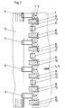
- Ein Anlegetisch 1 ist in bekannter und in der Zeichnung nicht dargestellten Weise mit Fördermitteln für geschuppt herangeführte Bogen 4, 5 ausgerüstet, die zu Vordermarken 11 gefördert werden. Schwinggreifer 8 einer Vorgreiferschwinganlage 2 übernehmen den ausgerichteten Bogen 4 am vorderen Ende des Anlegetisches 1 und übergeben ihn direkt an in der Zeichnung nicht dargestellte Greifer eines Druckzylinders 3. Die Zeichnung zeigt deutlich, daß die Ebene des Anlagetisches 1 den Druckzylinder 3 schneidet.
- Die Bahn 10 des unteren Endes der Schwinggreifer 8 der Vorgreiferschwinganlage 2 ist in Fig. 1 dargestellt.
- Unter der Bahn 10 des unteren Endes der zum Druckzylinder 3 hinschwenkenden Schwinggreifer 8 sind Bogenleitzungen 6 über die Bogenbreite verteilt angeordnet. Am Anlegetisch 1 steht dabei zwischen den schwingenden Schwinggreifern 8 ausreichend Raum zum Anbringen einzelner Bogenleitzungen 6 zur Verfügung (siehe Fig. 2). Die Bogenleitzungen 6 erstrecken sich vom Anlegetisch 1 zum Druckzylinder 3 der Bahn 10 des unteren Endes der zum Druckzylinder 3 hinschwenkenden Schwinggreifer 8 annähernd angeglichen. Dadurch wird partiell der Raum zwischen dem Druckzylinder 3 und dem vorderen Ende des Anlegetisches 1 in einer Weise überbrückt, das der beschriebene Peitscheneffekt mit einer Lockenbildung nach oben am Bogenende und der Kollisionsgefahr mit den schwingenden Schwinggreifern 8 verhindert wird.
- Es ist bekannt, daß Aussparungen 12 im Anlegetisch 1 vorgesehen sind, um den Bogen 4 nach seiner Ausrichtung an den Vordermarken 11 zu erfassen.
- An dem einen Ende der Bogenleitzungen 6 sind Bohrungen 7, 9 vorgesehen, durch die beispielsweise Schrauben oder dgl. Verbindungselemente geführt werden können, um die Bogenleitzungen 6 von unten am Anlegetisch 1 stationär zu befestigen.
-
- 1
- Anlegetisch
- 2
- Vorgreiferschwinganlage
- 3
- Druckzylinder
- 4
- Bogen
- 5
- nächstfolgender Bogen
- 6
- Bogenleitzunge
- 7
- Bohrung
- 8
- Schwinggreifer
- 9
- Bohrung
- 10
- Bahn des unteren Endes der Schwinggreifers
- 11
- Vordermarke
- 12
- Aussparung
Claims (2)
Priority Applications (1)
| Application Number | Priority Date | Filing Date | Title |
|---|---|---|---|
| AT89115816T ATE73106T1 (de) | 1988-09-03 | 1989-08-28 | Mechanische bogenleiteinrichtung in der bogenanlage an druckmaschinen. |
Applications Claiming Priority (2)
| Application Number | Priority Date | Filing Date | Title |
|---|---|---|---|
| DE3830070 | 1988-09-03 | ||
| DE3830070A DE3830070A1 (de) | 1988-09-03 | 1988-09-03 | Mechanische bogenleiteinrichtung in der bogenanlage an druckmaschinen |
Publications (2)
| Publication Number | Publication Date |
|---|---|
| EP0358076A1 EP0358076A1 (de) | 1990-03-14 |
| EP0358076B1 true EP0358076B1 (de) | 1992-03-04 |
Family
ID=6362289
Family Applications (1)
| Application Number | Title | Priority Date | Filing Date |
|---|---|---|---|
| EP89115816A Expired - Lifetime EP0358076B1 (de) | 1988-09-03 | 1989-08-28 | Mechanische Bogenleiteinrichtung in der Bogenanlage an Druckmaschinen |
Country Status (4)
| Country | Link |
|---|---|
| EP (1) | EP0358076B1 (de) |
| AT (1) | ATE73106T1 (de) |
| DE (2) | DE3830070A1 (de) |
| ES (1) | ES2030567T3 (de) |
Families Citing this family (1)
| Publication number | Priority date | Publication date | Assignee | Title |
|---|---|---|---|---|
| DE10355459A1 (de) * | 2003-11-27 | 2005-06-23 | Koenig & Bauer Ag | Anlegtisch |
Family Cites Families (4)
| Publication number | Priority date | Publication date | Assignee | Title |
|---|---|---|---|---|
| GB1175854A (en) * | 1967-06-28 | 1970-01-01 | Gestetner Ltd | Improvements relating to sheet handling apparatus |
| DE2330484C3 (de) * | 1973-06-15 | 1980-08-14 | Koenig & Bauer Ag, 8700 Wuerzburg | Vorrichtung zum Anlegen und Zuführen von vereinzelten, geschuppt zugeführten Bogen in Bogenrotationsdnickm aschinen |
| DE2724856C3 (de) * | 1977-06-02 | 1984-06-20 | Heidelberger Druckmaschinen Ag, 6900 Heidelberg | Bogenrotationsdruckmaschine |
| DD203887A1 (de) * | 1981-12-31 | 1983-11-09 | Dieter Erfurt | Einrichtung zur unterstuetzung der bogenfoerderung und -uebergabe |
-
1988
- 1988-09-03 DE DE3830070A patent/DE3830070A1/de not_active Ceased
-
1989
- 1989-08-28 EP EP89115816A patent/EP0358076B1/de not_active Expired - Lifetime
- 1989-08-28 AT AT89115816T patent/ATE73106T1/de not_active IP Right Cessation
- 1989-08-28 ES ES198989115816T patent/ES2030567T3/es not_active Expired - Lifetime
- 1989-08-28 DE DE8989115816T patent/DE58900913D1/de not_active Expired - Lifetime
Also Published As
| Publication number | Publication date |
|---|---|
| EP0358076A1 (de) | 1990-03-14 |
| ATE73106T1 (de) | 1992-03-15 |
| DE3830070A1 (de) | 1990-03-15 |
| DE58900913D1 (de) | 1992-04-09 |
| ES2030567T3 (es) | 1992-11-01 |
Similar Documents
| Publication | Publication Date | Title |
|---|---|---|
| DE4239089B4 (de) | Verfahren zur Registerkorrektur von Druckplatten | |
| DE102007049643B4 (de) | Verfahren und Vorrichtung zum Wenden eines Bogens während des Förderns durch eine Druckmaschine | |
| DE4030070C2 (de) | Bogenspeichereinheit an Rotationsdruckmaschinen | |
| CH646378A5 (de) | Einrichtung zur steuerung von saugerschwingern in bogenfuehrungszylindern. | |
| DE19547580C2 (de) | Leiteinrichtung für Bogen auf Speichertrommeln | |
| DE2452050C2 (de) | Vorrichtung zum passergerechten Anlegen von Bogen in Bogenrotationsdruckmaschinen | |
| EP0225994A1 (de) | Verfahren und Vorrichtung zum Abbremsen und Auslegen von in einer Druckmaschine bedruckten Bogen oder Bogenpaketen | |
| DE19901699A1 (de) | Verfahren und eine Vorrichtung zur Durchführung des Verfahrens zur Beseitigung von rhythmischen Passerfehlern in Rotationsdruckmaschinen | |
| EP0358076A1 (de) | Mechanische Bogenleiteinrichtung in der Bogenanlage an Druckmaschinen | |
| EP0170962B1 (de) | Vorrichtung zum Transportieren von Bogen hinter einer Auslegertrommel | |
| DE2452051A1 (de) | Vorrichtung zum passergerechten anlegen von bogen in bogenrotationsdruckmaschinen | |
| EP0778129B1 (de) | Digitale Druckmaschine und Verfahren zum Bogentransport dafür | |
| DE69809657T2 (de) | Vorrichtung zum Drehen eines einer Etikettiermaschine zugeführten Etiketts | |
| DE3842390C3 (de) | Steuervorrichtung | |
| DE10033490B4 (de) | Einrichtung zum seitlichen Ausrichten von Bogen | |
| CH651501A5 (en) | Sheet-fed rotary printing machine having at least one printing unit | |
| DE102005012527A1 (de) | Anlegeeinheit für eine Bogenverarbeitungsmaschine, Bogenverarbeitungsmaschine und Verfahren zum Anlegen von Bogen | |
| DE10348306B4 (de) | Greifersystem | |
| DE19720742C2 (de) | Einrichtung in Bogenauslegern | |
| DD273416A1 (de) | Vorrichtung zum fliessenden transport von bogen | |
| EP0725026B1 (de) | Vorrichtung zur Vermeidung von Passerfehlern | |
| EP0374496A2 (de) | Einrichtung zum Ausrichten von Voderkanten von Bogen | |
| EP3162747A1 (de) | Ausleger mit blaseinrichtung | |
| EP1120249B1 (de) | Bogenleiteinrichtung | |
| DE19720740C1 (de) | Schneideinrichtung zum Trennen von Bogen in einer Druckmaschine |
Legal Events
| Date | Code | Title | Description |
|---|---|---|---|
| PUAI | Public reference made under article 153(3) epc to a published international application that has entered the european phase |
Free format text: ORIGINAL CODE: 0009012 |
|
| 17P | Request for examination filed |
Effective date: 19891228 |
|
| AK | Designated contracting states |
Kind code of ref document: A1 Designated state(s): AT BE CH DE ES FR GB IT LI NL SE |
|
| 17Q | First examination report despatched |
Effective date: 19910729 |
|
| ITF | It: translation for a ep patent filed | ||
| GRAA | (expected) grant |
Free format text: ORIGINAL CODE: 0009210 |
|
| AK | Designated contracting states |
Kind code of ref document: B1 Designated state(s): AT BE CH DE ES FR GB IT LI NL SE |
|
| REF | Corresponds to: |
Ref document number: 73106 Country of ref document: AT Date of ref document: 19920315 Kind code of ref document: T |
|
| ET | Fr: translation filed | ||
| REF | Corresponds to: |
Ref document number: 58900913 Country of ref document: DE Date of ref document: 19920409 |
|
| GBT | Gb: translation of ep patent filed (gb section 77(6)(a)/1977) | ||
| REG | Reference to a national code |
Ref country code: ES Ref legal event code: FG2A Ref document number: 2030567 Country of ref document: ES Kind code of ref document: T3 |
|
| PLBE | No opposition filed within time limit |
Free format text: ORIGINAL CODE: 0009261 |
|
| STAA | Information on the status of an ep patent application or granted ep patent |
Free format text: STATUS: NO OPPOSITION FILED WITHIN TIME LIMIT |
|
| 26N | No opposition filed | ||
| EAL | Se: european patent in force in sweden |
Ref document number: 89115816.4 |
|
| PGFP | Annual fee paid to national office [announced via postgrant information from national office to epo] |
Ref country code: NL Payment date: 19950713 Year of fee payment: 7 |
|
| PGFP | Annual fee paid to national office [announced via postgrant information from national office to epo] |
Ref country code: FR Payment date: 19950714 Year of fee payment: 7 |
|
| PGFP | Annual fee paid to national office [announced via postgrant information from national office to epo] |
Ref country code: CH Payment date: 19950717 Year of fee payment: 7 |
|
| PGFP | Annual fee paid to national office [announced via postgrant information from national office to epo] |
Ref country code: BE Payment date: 19950720 Year of fee payment: 7 |
|
| PGFP | Annual fee paid to national office [announced via postgrant information from national office to epo] |
Ref country code: GB Payment date: 19950721 Year of fee payment: 7 |
|
| PGFP | Annual fee paid to national office [announced via postgrant information from national office to epo] |
Ref country code: AT Payment date: 19950724 Year of fee payment: 7 |
|
| PGFP | Annual fee paid to national office [announced via postgrant information from national office to epo] |
Ref country code: SE Payment date: 19950726 Year of fee payment: 7 |
|
| PGFP | Annual fee paid to national office [announced via postgrant information from national office to epo] |
Ref country code: ES Payment date: 19950802 Year of fee payment: 7 |
|
| PG25 | Lapsed in a contracting state [announced via postgrant information from national office to epo] |
Ref country code: GB Effective date: 19960828 Ref country code: AT Effective date: 19960828 |
|
| PG25 | Lapsed in a contracting state [announced via postgrant information from national office to epo] |
Ref country code: SE Effective date: 19960829 Ref country code: ES Free format text: LAPSE BECAUSE OF THE APPLICANT RENOUNCES Effective date: 19960829 |
|
| PG25 | Lapsed in a contracting state [announced via postgrant information from national office to epo] |
Ref country code: LI Effective date: 19960831 Ref country code: CH Effective date: 19960831 Ref country code: BE Effective date: 19960831 |
|
| BERE | Be: lapsed |
Owner name: MAN-ROLAND DRUCKMASCHINEN A.G. Effective date: 19960831 |
|
| PG25 | Lapsed in a contracting state [announced via postgrant information from national office to epo] |
Ref country code: NL Effective date: 19970301 |
|
| REG | Reference to a national code |
Ref country code: CH Ref legal event code: PL |
|
| GBPC | Gb: european patent ceased through non-payment of renewal fee |
Effective date: 19960828 |
|
| PG25 | Lapsed in a contracting state [announced via postgrant information from national office to epo] |
Ref country code: FR Effective date: 19970430 |
|
| NLV4 | Nl: lapsed or anulled due to non-payment of the annual fee |
Effective date: 19970301 |
|
| EUG | Se: european patent has lapsed |
Ref document number: 89115816.4 |
|
| REG | Reference to a national code |
Ref country code: FR Ref legal event code: ST |
|
| PGFP | Annual fee paid to national office [announced via postgrant information from national office to epo] |
Ref country code: DE Payment date: 19990722 Year of fee payment: 11 |
|
| REG | Reference to a national code |
Ref country code: ES Ref legal event code: FD2A Effective date: 19991007 |
|
| PG25 | Lapsed in a contracting state [announced via postgrant information from national office to epo] |
Ref country code: DE Free format text: LAPSE BECAUSE OF NON-PAYMENT OF DUE FEES Effective date: 20010501 |
|
| PG25 | Lapsed in a contracting state [announced via postgrant information from national office to epo] |
Ref country code: IT Free format text: LAPSE BECAUSE OF NON-PAYMENT OF DUE FEES;WARNING: LAPSES OF ITALIAN PATENTS WITH EFFECTIVE DATE BEFORE 2007 MAY HAVE OCCURRED AT ANY TIME BEFORE 2007. THE CORRECT EFFECTIVE DATE MAY BE DIFFERENT FROM THE ONE RECORDED. Effective date: 20050828 |