EP0358101A2 - Plug for a plug and socket connection - Google Patents
Plug for a plug and socket connection Download PDFInfo
- Publication number
- EP0358101A2 EP0358101A2 EP89116046A EP89116046A EP0358101A2 EP 0358101 A2 EP0358101 A2 EP 0358101A2 EP 89116046 A EP89116046 A EP 89116046A EP 89116046 A EP89116046 A EP 89116046A EP 0358101 A2 EP0358101 A2 EP 0358101A2
- Authority
- EP
- European Patent Office
- Prior art keywords
- housing
- bayonet ring
- plug
- plug according
- bayonet
- Prior art date
- Legal status (The legal status is an assumption and is not a legal conclusion. Google has not performed a legal analysis and makes no representation as to the accuracy of the status listed.)
- Granted
Links
Images

Classifications
-
- H—ELECTRICITY
- H01—ELECTRIC ELEMENTS
- H01R—ELECTRICALLY-CONDUCTIVE CONNECTIONS; STRUCTURAL ASSOCIATIONS OF A PLURALITY OF MUTUALLY-INSULATED ELECTRICAL CONNECTING ELEMENTS; COUPLING DEVICES; CURRENT COLLECTORS
- H01R13/00—Details of coupling devices of the kinds covered by groups H01R12/70 or H01R24/00 - H01R33/00
- H01R13/62—Means for facilitating engagement or disengagement of coupling parts or for holding them in engagement
- H01R13/625—Casing or ring with bayonet engagement
Definitions
- the invention relates to a plug for a plug connection for an electrical connection, in particular of motor vehicle trailers, with a housing, a bayonet connection part with a rotatable bayonet ring and a cover platform.
- the invention has for its object to provide a plug for a plug connection for an electrical connection, which is easy to use.
- the lid platform and the housing are firmly connected to one another and, consequently, the plug is directly in the insertion position when the can lid and the lid platform are aligned.
- the insertion process is extremely simplified in this way for the operators.
- the cover platform and the housing are formed in one piece, which simplifies assembly.
- An intermediate piece is expediently included in the connection of the cover platform / housing, so that there is a solid structural unit.
- the bayonet ring advantageously has a cam projection which can be locked with the cover platform.
- This cam projection has different functions. On the one hand, it makes the respective position of the bayonet ring visible, i.e. it can be seen with the naked eye whether the bayonet ring is in the locked or in the unlocked position.
- the cam projection ensures that the can lid only fully rests on the lid platform when the cam projection is in the locking position.
- the cam projection has a sharp-edged nose.
- the locking of the cam projection with the lid platform is particularly fixed, and unlocking can only take place if the can lid is lifted beforehand by hand. This creates an additional safeguard against unlocking.
- the cam projection has a rounded nose. This constructive measure ensures that the can lid automatically lifts during the unlocking process through the rounded nose and the can lid no longer has to be lifted by hand. This enables unlocking with one hand, whereby the lid platform is free and the plug can be pulled axially out of the socket.
- the operation of the plug is extremely simplified in practice.
- the cam projection can be arranged on the central axis assigned to the cover platform. Depending on the design or other requirements, however, a lateral arrangement more to the plug or to the connection side is possible.
- a recess in the bayonet ring is advantageously provided as a viewing window on the housing.
- This enables an optical marking, e.g. in the form of an engraving.
- the unlocking and locking positions can also be made visible to the operator by the respective marking display becoming visible when these positions are reached.
- a cap is expediently firmly connected to the bayonet ring.
- Such a non-detachable and non-rotatable connection can be realized, for example, by a snap connection.
- the bayonet ring has a neck with the bayonet grooves.
- an annular disk for example made of spring bronze, is provided between the housing and the bayonet ring with an anchoring projection and a resilient projection, a recess in the housing being provided for the anchoring projection and a recess in the bayonet ring for the resilient projection.
- the washer is non-rotatably connected to the housing by means of the anchoring projection.
- the resilient projection enables a non-rotatable connection to the bayonet ring in the extended position. In this way, the housing of the plug with the bayonet ring is rotationally fixed in the unlocked position connected, so that an unintentional turning of the bayonet ring with respect to the housing, at least when not plugged in, is not possible. If the plug is inserted into the socket in the unlocked position, the resilient projection is pressurized and the lock is released. As a result, the bayonet ring can be rotated to lock the plug in the socket.
- an axially adjustable plunger is mounted in the bayonet ring, which is in engagement with the resilient projection with its head located at the rear end and for whose head a rotating groove is provided in the housing.
- the plunger is pushed backwards and presses the resilient projection of the ring washer backwards, which releases the lock.
- the plunger In the rear position, the plunger is displaced or guided in a rotating groove when the bayonet ring is rotated, thereby ensuring that the bayonet ring can be rotated in the inserted position.
- the rotary groove expediently has a locking lug at the end, which delimits a locking recess in accordance with the locking of the bayonet ring.
- the tappet shaft then runs over the latching lug into the locking recess, which is made possible by the elasticity of the housing made of plastic. This ensures a secure locking of the connector. Due to the design, a slightly higher torque must be used to unlock the plug than to lock it.
- a groove is provided in the bayonet ring for the locking lug.
- the exemplary embodiments of the connector according to the invention shown in the drawing relate to a thirteen-pin connector according to DIN draft 72570, part 1.
- DIN draft 72570 part 1.
- the area of application is much wider and the illustration serves only to illustrate the principle of the invention.
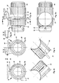
- the connector shown is provided for a plug connection for an electrical connection of motor vehicle trailers. It comprises a housing 10, a rotatable bayonet ring 20 and a cover platform 30 and an intermediate piece 40, e.g. 1a can be seen.
- the lid platform 30 serves to support a can lid 50 when the socket is open. This is with protrusions, e.g. Edge lugs (see FIG. 3d), provided for engagement in corresponding bayonet grooves 22.
- the lid platform 30, the intermediate piece 40 and the bayonet ring 20 are formed in one piece in the illustrated embodiment.
- the bayonet ring 20 is provided with a cam projection 24 which extends radially outward (see FIGS. 1b, 2b).
- the cam projection 24 is clearly recognizable from the outside in the respective position and engages under a corresponding lateral projection in the edge area 52 of the can lid 50 which is formed on the inside with reinforcing ribs 54.
- the cam projection 24 is formed with a sharp-edged nose 26 which engages firmly under the edge area 52 when the bayonet ring 20 is in the locked position.
- the cam projection is provided with a rounded nose 28 for easier unlocking.
- a recess 60 is provided in the bayonet ring 20 as a viewing window on the housing 10.
- the recess 60 releases a label “locked” or “unlocked” depending on the position, so that the respective plug position is easily visible.
- the bayonet ring 20 is firmly connected at the rear end with an aligned cap 62. At the front end it is formed with a neck 64 in which the bayonet grooves 22 are located. At the rear end, the housing 10 carries a rotatable attachment 66, which ensures the sealing of the plug.
- annular disk 70 is arranged between the housing 10 and the bayonet ring 20.
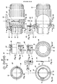
- the washer 70 has a fixed anchoring projection 72 and a resilient projection 74. With the anchoring projection 72, the annular disk 70 firmly engages in a recess or groove 12 in the housing 10.
- the resilient projection 74 protrudes into a recess 68 in the bayonet ring 20, as can best be seen from FIG. 3c.
- a plunger 80 is axially adjustable in the bayonet ring 20. Its head 82 located at the rear end engages with the resilient projection 74 of the annular disk 70.
- the plunger is shown in the front position corresponding to the unlocking position of the plug, while the adjustment movement of the plunger 80 is illustrated by means of edge tabs 4 located on the socket neck 2 in Fig. 3d and 3e.
- the resilient projection 74 becomes the ring disk 70 pressed into the plane of the annular disk in such a way that the head 82 of the plunger 80 reaches a rotary groove 14 in the housing 10, in which the head 82 can be guided when the bayonet ring is rotated.
- the rotary groove 14 has a locking lug 16 at the end, to which a locking recess 18 connects.
- the locking recess 18 serves for the engagement of the shaft 84 of the plunger 80 and is aligned with the bayonet catch, ie the bayonet grooves 20.
- a groove 58 is provided for the detent 16.
- FIG. 3a A contact insert 90 with plug contact pins 92 accommodated in the housing 10 is illustrated in FIG. 3a.
- the rotation of the bayonet ring 20 with locking / unlocking is explained below. If the plug is not inserted into the socket, the plug is in the unlocked position. Here, the housing 10 and the bayonet ring 20 are fixed by means of the washer 70, i.e. non-rotatable, connected. If the plug is then inserted into the socket with the cover platform 30 aligned with the socket cover 50, the edge lugs 4 (e.g. 3) provided on the socket neck 2 penetrate into the axial sections of the bayonet grooves 22, at the same time displacing the plunger 80 to the rear. The plunger 80 presses the resilient projection 74 of the ring disk 70 to the rear, so that the bayonet ring 20 and the housing 10 are no longer coupled to one another in a rotationally secure manner.
- the edge lugs 4 e.g. 3
- the shaft 84 of the plunger 80 slides easily over the curved outer surface of the housing 10 until it reaches Latch 16 arrives.
- the shaft 84 can be rotated over the locking lug 16 and snaps into the locking recess 18, as a result of which the plug is additionally locked.
Landscapes
- Details Of Connecting Devices For Male And Female Coupling (AREA)
- Connector Housings Or Holding Contact Members (AREA)
Abstract
Die Erfindung bezieht sich auf einen Stecker für eine Steckverbindung für einen elektrischen Anschluß, insbesondere von Kraftfahrzeuanhängern, mit einem Gehäuse (10) einem Bajonettanschlußteil mit drehbarem Bajonettring (20) und einer Deckelplattform (30). Der Gegenstand der Erfindung zeichnet sich dadurch aus, daß die Deckelplattform (30) und das Gehäuse (10) fest miteinander verbunden sind.The invention relates to a plug for a plug connection for an electrical connection, in particular of motor vehicle trailers, with a housing (10), a bayonet connection part with a rotatable bayonet ring (20) and a cover platform (30). The object of the invention is characterized in that the cover platform (30) and the housing (10) are firmly connected to one another.
Description
Die Erfindung bezieht sich auf einen Stecker für eine Steckverbindung für einen elektrischen Anschluß, insbesondere von Kraftfahrzeuganhängern, mit einem Gehäuse, einem Bajonettanschlußteil mit drehbarem Bajonettring und einer Deckelplattform.The invention relates to a plug for a plug connection for an electrical connection, in particular of motor vehicle trailers, with a housing, a bayonet connection part with a rotatable bayonet ring and a cover platform.
Bei einem Stecker gemäß DE-GM 86 15 641 ist die Deckelplattform fest mit dem Bajonettring verbunden. Wenn sich der Bajonettring in der entriegelten Stellung für das Einstecken des Steckers befindet, ist die Deckelplattform daher in bezug auf den Dosendeckel etwa um 100o verdreht. Infolgedessen ist es für Bedienungspersonen mit wenig Übung schwierig, die korrekte Einsteckstellung zu finden, denn sie versuchen in der Regel, die Deckelplattform mit dem Dosendeckel auszurichten.With a plug according to DE-GM 86 15 641, the cover platform is firmly connected to the bayonet ring. When the bayonet ring in the unlocked position for the insertion of the plug, the lid platform is therefore rotated about relative to the can lid by 100 o. As a result, it is difficult for operators with little practice to find the correct insertion position because they usually try to align the lid platform with the can lid.
Der Erfindung liegt die Aufgabe zugrunde, einen Stecker für eine Steckverbindung für einen elektrischen Anschluß zu schaffen, der bedienungsfreundlich ist.The invention has for its object to provide a plug for a plug connection for an electrical connection, which is easy to use.
Diese Aufgabe ist bei einem Stecker mit den Merkmalen des Anspruchs 1 gelöst. Vorteilhafte Weitergestaltungen des erfindungsgemäßen Steckers sind Gegenstand der Unteransprüche.This object is achieved with a plug with the features of claim 1. Advantageous further developments of the connector according to the invention are the subject of the dependent claims.
Bei dem erfindungsgemäßen Stecker sind die Deckelplattform und das Gehäuse fest miteinander verbunden und demzufolge befindet sich der Stecker direkt in der Einsteckstellung, wenn der Dosendeckel und die Deckelplattform ausgerichtet sind. Der Einsteckvorgang ist auf diese Weise für die Bedienungspersonen außerordentlich vereinfacht.In the plug according to the invention, the lid platform and the housing are firmly connected to one another and, consequently, the plug is directly in the insertion position when the can lid and the lid platform are aligned. The insertion process is extremely simplified in this way for the operators.
Bei einer vorteilhaften Ausgestaltung des erfindungsgemäßen Steckers sind die Deckelplattform und das Gehäuse einstückig ausgebildet, wodurch die Montage vereinfacht ist.In an advantageous embodiment of the plug according to the invention, the cover platform and the housing are formed in one piece, which simplifies assembly.
In der Verbindung Deckelplattform/Gehäuse ist zweckmäßig ein Zwischenstück miteinbegriffen, so daß sich eine feste Baueinheit ergibt.An intermediate piece is expediently included in the connection of the cover platform / housing, so that there is a solid structural unit.
Der Bajonettring weist vorteilhaft einen Nockenvorsprung auf, der mit der Deckelplattform verriegelbar ist. Dieser Nockenvorsprung hat verschiedene Funktionen. Einerseits macht er die jeweilige Stellung des Bajonettrings sichtbar, d.h. es kann mit bloßem Auge erkannt werden, ob sich der Bajonettring in der verriegelten oder in der entriegelten Stellung befindet. Außerdem stellt der Nockenvorsprung sicher, daß der Dosendeckel nur dann voll zur Auflage auf der Deckelplattform gelangt, wenn sich der Nockenvorsprung in der Verriegelungsstellung befindet.The bayonet ring advantageously has a cam projection which can be locked with the cover platform. This cam projection has different functions. On the one hand, it makes the respective position of the bayonet ring visible, i.e. it can be seen with the naked eye whether the bayonet ring is in the locked or in the unlocked position. In addition, the cam projection ensures that the can lid only fully rests on the lid platform when the cam projection is in the locking position.
Gemäß einer bevorzugten Ausgestaltung des Nockenvorsprungs weist dieser eine scharfkantige Nase auf. Hierdurch wird die Verriegelung des Nockenvorsprungs mit der Deckelplattform besonders fixiert, und es kann eine Entriegelung nur stattfinden, wenn der Dosendeckel vorher von Hand angehoben wird. Dadurch wird eine zusätzliche Sicherung gegen Entriegelung geschaffen.According to a preferred embodiment of the cam projection, it has a sharp-edged nose. As a result, the locking of the cam projection with the lid platform is particularly fixed, and unlocking can only take place if the can lid is lifted beforehand by hand. This creates an additional safeguard against unlocking.
Gemäß einer alternativen Ausführungsform weist der Nockenvorsprung eine abgerundete Nase auf. Durch diese konstruktive Maßnahme wird erreicht, daß sich der Dosendeckel beim Entriegelungsvorgang durch die abgerundete Nase selbsttätig anhebt und der Dosendeckel nicht mehr von Hand angehoben werden muß. Dies ermöglicht eine Entriegelung mit einer Hand, wobei die Deckelplattform frei wird und der Stecker axial aus der Steckdose herausgezogen werden kann. Hier durch ist die Bedienung des Steckers in der Praxis außerordentlich vereinfacht.According to an alternative embodiment, the cam projection has a rounded nose. This constructive measure ensures that the can lid automatically lifts during the unlocking process through the rounded nose and the can lid no longer has to be lifted by hand. This enables unlocking with one hand, whereby the lid platform is free and the plug can be pulled axially out of the socket. Here the operation of the plug is extremely simplified in practice.
Der Nockenvorsprung kann auf der der Deckelplattform zugeordneten Mittelachse angeordnet sein. Je nach den konstruktiven oder sonstigen Erfordernissen ist jedoch auch eine seitliche Anordnung mehr zur Steck- oder zur Anschlußseite hin möglich.The cam projection can be arranged on the central axis assigned to the cover platform. Depending on the design or other requirements, however, a lateral arrangement more to the plug or to the connection side is possible.
Vorteilhaft ist im Bajonettring eine Aussparung als Sichtfenster auf das Gehäuse vorgesehen. Dies ermöglicht es, auf dem Gehäuse eine optische Markierung, z.B. in Form einer Gravur, vorzusehen. Mittels einer derartigen an geeigneten Stellen vorgesehenen Markierung können die Entriegelungs- und Verriegelungsstellungen zusätzlich für die Bedienungsperson sichtbar gemacht werden, indem mit Erreichen dieser Stellungen jeweils die entsprechende Markierungsanzeige sichtbar wird.A recess in the bayonet ring is advantageously provided as a viewing window on the housing. This enables an optical marking, e.g. in the form of an engraving. By means of such a marking provided at suitable points, the unlocking and locking positions can also be made visible to the operator by the respective marking display becoming visible when these positions are reached.
Mit dem Bajonettring ist zweckmäßig eine Kappe fest verbunden. Eine derartige unlösbare und unverdrehbare Verbindung kann beispielsweise durch eine Schnappverbindung realisiert sein. Am anderen zur Steckdose weisenden Ende trägt der Bajonettring einen Hals mit den Bajonettnuten.A cap is expediently firmly connected to the bayonet ring. Such a non-detachable and non-rotatable connection can be realized, for example, by a snap connection. At the other end facing the socket, the bayonet ring has a neck with the bayonet grooves.
Bei einem bevorzugten Ausführungsbeispiel des erfindungsgemäßen Steckers ist zwischen dem Gehäuse und dem Bajonettring eine Ringscheibe, z.B. aus Federbronze, mit einem Verankerungsvorsprung und einem federnden Vorsprung vorgesehen, wobei für den Verankerungsvorsprung eine Aussparung im Gehäuse und für den federnden Vorsprung eine Aussparung im Bajonettring vorgesehen ist. Mittels des Verankerungsvorsprungs ist die Ringscheibe unverdrehbar mit dem Gehäuse verbunden. Der federnde Vorsprung ermöglicht in der ausgefederten Stellung eine unverdrehbare Verbindung mit dem Bajonettring. Auf diese Weise ist das Gehäuse des Steckers mit dem Bajonettring in der entriegelten Stellung drehfest verbunden, so daß ein unbeabsichtigtes Verdrehen des Bajonettrings in bezug auf das Gehäuse, jedenfalls im nicht eingesteckten Zustand, nicht möglich ist. Wird der Stecker in der entriegelten Stellung in die Steckdose eingeführt, wird der federnde Vorsprung druckbeaufschlagt und die Arretierung wird gelöst. Infolgedessen kann der Bajonettring zur Verriegelung des Steckers in der Steckdose verdreht werden.In a preferred embodiment of the connector according to the invention, an annular disk, for example made of spring bronze, is provided between the housing and the bayonet ring with an anchoring projection and a resilient projection, a recess in the housing being provided for the anchoring projection and a recess in the bayonet ring for the resilient projection. The washer is non-rotatably connected to the housing by means of the anchoring projection. The resilient projection enables a non-rotatable connection to the bayonet ring in the extended position. In this way, the housing of the plug with the bayonet ring is rotationally fixed in the unlocked position connected, so that an unintentional turning of the bayonet ring with respect to the housing, at least when not plugged in, is not possible. If the plug is inserted into the socket in the unlocked position, the resilient projection is pressurized and the lock is released. As a result, the bayonet ring can be rotated to lock the plug in the socket.
Vorzugsweise ist im Bajonettring ein axial verstellbarer Stößel gelagert, der mit seinem am hinteren Ende befindlichen Kopf mit dem federnden Vorsprung in Eingriff steht und für dessen Kopf im Gehäuse eine Drehnut vorgesehen ist. Beim Einstecken des Steckers wird der Stößel nach hinten geschoben und drückt den federnden Vorsprung der Ringscheibe nach hinten, wodurch die Arretierung aufgehoben wird. In der hinteren Stellung wird der Stößel bei Verdrehen des Bajonettrings in einer Drehnut verschoben bzw. geführt, wodurch die Verdrehbarkeit des Bajonettrings in der eingesteckten Stellung sichergestellt ist.Preferably, an axially adjustable plunger is mounted in the bayonet ring, which is in engagement with the resilient projection with its head located at the rear end and for whose head a rotating groove is provided in the housing. When the plug is inserted, the plunger is pushed backwards and presses the resilient projection of the ring washer backwards, which releases the lock. In the rear position, the plunger is displaced or guided in a rotating groove when the bayonet ring is rotated, thereby ensuring that the bayonet ring can be rotated in the inserted position.
Zweckmäßig weist die Drehnut am Ende eine Rastnase auf, die eine Verriegelungsaussparung entsprechend der Rasterung des Bajonettrings begrenzt. Am Ende der Verdrehstellung läuft dann der Stößelschaft über die Rastnase in die Verriegelungsaussparung, was durch die Elastizität des aus Kunststoff hergestellten Gehäuses ermöglicht ist. Hierdurch ist eine sichere Verriegelung des Steckers gewährleistet. Zur Entriegelung des Steckers muß konstruktionsbedingt ein etwas höheres Drehmoment als zum Verriegeln aufgewendet werden.The rotary groove expediently has a locking lug at the end, which delimits a locking recess in accordance with the locking of the bayonet ring. At the end of the rotational position, the tappet shaft then runs over the latching lug into the locking recess, which is made possible by the elasticity of the housing made of plastic. This ensures a secure locking of the connector. Due to the design, a slightly higher torque must be used to unlock the plug than to lock it.
Um eine freie Beweglichkeit der Rastnase bei Verdrehung des Bajonettrings sicherzustellen, ist im Bajonettring eine Nut für die Rastnase vorgesehen.In order to ensure that the locking lug can move freely when the bayonet ring is rotated, a groove is provided in the bayonet ring for the locking lug.
Die Erfindung wird im folgenden weiter anhand bevorzugter Ausführungsbeispiele und der Zeichnung erläutert. In der Zeichnung zeigen:
- Fig. 1a eine Seitenansicht des Steckers in der entriegelten Stellung,
- Fig. 1b eine Schnittansicht längs Linie A-A in Fig. 1a,
- Fig. 1c eine Ansicht des Steckers von Fig. 1a, in Richtung des Pfeils B in Fig. 1b gesehen,
- Fig. 2a eine Ansicht des Steckers in entriegelter Stellung,
- Fig. 2b eine Schnittansicht des Steckers längs Linie A-A in Fig. 1a, jedoch in verriegelter Stellung,
- Fig. 2c eine Ansicht des Steckers von Fig. 2a, in Richtung des Pfeils C in Fig. 2b gesehen,
- Fig. 2d eine Teilschnittansicht des Dosendeckels mit Einhand-Entriegelung,
- Fig. 3a eine seitliche Teilschnittansicht des Steckers in der entriegelten Stellung,
- Fig. 3b eine Schnittansicht des Steckers längs Linie C-C in Fig. 3a,
- Fig. 3c bis 3f den Stecker in verschiedenen Einsteckstellungen,
- Fig. 4a eine Teilschnitt-Draufsicht des Steckers,
- Fig. 4b eine Schnittansicht des Steckers längs Linie A-A in Fig. 4a,
- Fig. 4c eine seitliche Ansicht einer zwischen Gehäuse und Deckelplattform vorgesehenen Ringscheibe,
- Fig. 4d eine Schnittansicht längs Linie B-B in Fig. 4A,
- Fig. 4e eine im Maßstab 2:1 vergrößerte Teilschnittansicht, die eine Rasteinrichtung im Gehäuse und eine Nut im Bajonettring veranschaulicht,
- Fig. 5 eine im Maßstab 2:1 vergrößerte Ansicht eines im Bajonettring gelagerten Stößels von vorne und von der Seite und
- Fig. 6 eine perspektivische, vergrößerte Ansicht der in Fig. 4c in Seitenansicht dargestellten Ringscheibe.
- 1a is a side view of the connector in the unlocked position,
- 1b is a sectional view along line AA in Fig. 1a,
- 1c is a view of the plug of Fig. 1a, seen in the direction of arrow B in Fig. 1b,
- 2a is a view of the connector in the unlocked position,
- 2b is a sectional view of the connector along line AA in Fig. 1a, but in the locked position,
- 2c is a view of the plug of Fig. 2a, seen in the direction of arrow C in Fig. 2b,
- 2d is a partial sectional view of the can lid with one-handed unlocking,
- 3a is a partial sectional side view of the connector in the unlocked position,
- 3b is a sectional view of the connector along line CC in Fig. 3a,
- 3c to 3f the plug in different insertion positions,
- 4a is a partial sectional plan view of the connector,
- 4b is a sectional view of the connector along line AA in Fig. 4a,
- 4c is a side view of an annular disk provided between the housing and the cover platform,
- 4d is a sectional view along line BB in Fig. 4A,
- 4e is a partial sectional view enlarged on a scale of 2: 1, which illustrates a latching device in the housing and a groove in the bayonet ring,
- Fig. 5 is a 2: 1 enlarged view of a plunger mounted in the bayonet ring from the front and from the side and
- Fig. 6 is a perspective, enlarged view of the ring disk shown in Fig. 4c in side view.
Die in der Zeichnung dargestellten Ausführungsbeispiele des erfindungsgemäßen Steckers beziehen sich auf einen dreizehnpoligen Stecker nach DIN-Entwurf 72570, Teil 1. Selbstverständlich ist der Anwendungsbereich viel weiter und die Darstellung dient lediglich zur Veranschaulichung des Erfindungsprinzips.The exemplary embodiments of the connector according to the invention shown in the drawing relate to a thirteen-pin connector according to DIN draft 72570, part 1. Of course, the area of application is much wider and the illustration serves only to illustrate the principle of the invention.
Der dargestellte Stecker ist für eine Steckverbindung für einen elektrischen Anschluß von Kraftfahrzeuganhängern vorgesehen. Er umfaßt ein Gehäuse 10, einen verdrehbaren Bajonettring 20 und eine Deckelplattform 30 sowie ein Zwischenstück 40, wie z.B. aus Fig. 1a ersichtlich ist. Die Deckelplattform 30 dient zur Auflage eines Dosendeckels 50 bei geöffneter Steckdose. Diese ist mit Vorsprüngen, z.B. Randnasen (vgl. Fig. 3d), für einen Eingriff in entsprechende Bajonettnuten 22 versehen.The connector shown is provided for a plug connection for an electrical connection of motor vehicle trailers. It comprises a
Die Deckelplattform 30, das Zwischenstück 40 und der Bajonettring 20 sind im veranschaulichten Ausführungsbeispiel einstückig ausgebildet. Der Bajonettring 20 ist mit einem Nockenvorsprung 24 versehen, der sich radial nach außen erstreckt (vgl. Fig. 1b, 2b) Der Nockenvorsprung 24 ist von außen deutlich erkennbar in der jeweiligen Stellung und greift unter einen entsprechenden seitlichen Vorsprung im Randbereich 52 des Dosendeckels 50, der auf der Innenseite mit Verstärkungsrippen 54 ausgebildet ist. In Fig. 2b ist der Nockenvorsprung 24 mit einer scharfkantigen Nase 26 ausgebildet, die fest unter dem Randbereich 52 in diesen eingreift, wenn sich der Bajonettring 20 in der verriegelten Stellung befindet. Bei der Variante gemäß Fig. 2d ist der Nockenvorsprung mit einer abgerundeten Nase 28 für eine leichtere Entriegelung versehen.The
Im Bajonettring 20 ist eine Aussparung 60 als Sichtfenster auf das Gehäuse 10 vorgesehen. Die Aussparung 60 gibt je nach Stellung eine Beschriftung "verriegelt" bzw. "entriegelt" frei, so daß die jeweilige Steckerstellung leicht ersichtlich ist.A
Der Bajonettring 20 ist am hinteren Ende mit einer fluchtend ausgebildeten Kappe 62 fest verbunden. Am vorderen Ende ist er mit einem Hals 64 ausgebildet, in dem sich die Bajonettnuten 22 befinden. Am rückwärtigen Ende trägt das Gehäuse 10 einen drehbaren Aufsatz 66, der die Abdichtung des Steckers sicherstellt.The
Zwischen dem Gehäuse 10 und dem Bajonettring 20 ist eine Ringscheibe 70 angeordnet. Wie insbesondere deutlich aus der perspektivischen Ansicht von Fig. 6 hervorgeht, weist die Ringscheibe 70 einen festen Verankerungsvorsprung 72 und einen federnden Vorsprung 74 auf. Mit dem Verankerungsvorsprung 72 greift die Ringscheibe 70 in eine Aussparung bzw. Nut 12 im Gehäuse 10 fest ein. Der federnde Vorsprung 74 ragt in eine Aussparung 68 im Bajonettring 20, wie am besten aus Fig. 3c ersichtlich ist.An
Ein Stößel 80 ist im Bajonettring 20 axial verstellbar gelagert. Sein am hinteren Ende befindlicher Kopf 82 steht mit dem federnden Vorsprung 74 der Ringscheibe 70 in Eingriff. In Fig. 3a ist der Stößel in der vorderen Stellung entsprechend der Entriegelungsstellung des Steckers dargestellt, während die Verstellbewegung des Stößels 80 mittels am Steckdosenhals 2 befindlicher Randnasen 4 in Fig. 3d und 3e veranschaulicht ist. Durch diese Verstellbewegung des Stößels 80 wird der federnde Vorsprung 74 der Ring scheibe 70 in die Ringscheibenebene gedrückt derart, daß der Kopf 82 des Stößels 80 in eine Drehnut 14 im Gehäuse 10 gelangt, in der der Kopf 82 bei Verdrehung des Bajonettrings führbar ist. Die Drehnut 14 weist am Ende eine Rastnase 16 auf, an die sich eine Verriegelungsaussparung 18 anschließt. Die Verriegelungsaussparung 18 dient für den Eingriff des Schaftes 84 des Stößels 80 und ist mit der Bajonettrasterung, d.h. den Bajonettnuten 20, ausgerichtet. Im Bajonettring 20 ist eine Nut 58 für die Rastnase 16 vorgesehen.A
In Fig. 3a ist ein im Gehäuse 10 aufgenommener Kontakteinsatz 90 mit Steckerkontaktstiften 92 veranschaulicht.A
Im folgenden wird die Verdrehung des Bajonettrings 20 mit Verriegelung/Entriegelung erläutert. Wenn der Stecker nicht in die Steckdose eingesteckt ist, befindet sich der Stecker in der entriegelten Position. Hierbei sind das Gehäuse 10 und der Bajonettring 20 mittels der Ringscheibe 70 fest, d.h. unverdrehbar, verbunden. Wird dann der Stecker mit nach dem Dosendeckel 50 ausgerichteter Deckelplattform 30 in die Steckdose eingeführt, dringen die am Steckdosenhals 2 vorgesehenen Randnasen 4 (z.B. 3) in die axialen Abschnitte der Bajonettnuten 22 ein, wobei sie zugleich den Stößel 80 nach hinten verschieben. Der Stößel 80 drückt dabei den federnden Vorsprung 74 der Ringscheibe 70 nach hinten, so daß der Bajonettring 20 und das Gehäuse 10 nicht mehr verdrehsicher miteinander gekoppelt sind.The rotation of the
In dieser Stellung ist es möglich, den Bajonettring 20 zu verdrehen, wobei der Stößel 80 in der Drehnut 14 im Gehäuse 10 geführt wird und gegen eine Rückverstellung nach vorne gesichert ist.In this position it is possible to turn the
Bei der Verdrehung des Bajonettrings 20 in die Verriegelungsstellung gleitet der Schaft 84 des Stößels 80 leicht über die gewölbte Außenfläche des Gehäuses 10, bis er zur Rastnase 16 gelangt. Infolge der Elastizität des aus Kunststoff hergestellten Gehäuses 10 und des Bajonettrings 20 kann der Schaft 84 über die Rastnase 16 hinweg gedreht werden und rastet in der Verriegelungsaussparung 18 ein, wodurch der Stecker zusätzlich verriegelt ist.When the
Zur Entriegelung muß zunächst ein höheres Drehmoment als für die Verriegelung aufgewendet werden, damit der Schaft 84 über die Nase 1 hinweggelangen kann. Ansonsten laufen bei der Entriegelung die Vorgänge umgekehrt zum Verriegelungsvorgang ab.A higher torque than that for the locking must first be used for unlocking so that the
Vorstehend ist die Erfindung anhand bevorzugter Ausführungsbeispiele und ausgewählter Merkmale beschrieben und dargestellt worden. Selbstverständlich ist die Erfindung nicht auf diese Darstellung beschränkt, sondern vielmehr können sämtliche Merkmale allein oder in beliebiger Kombination, auch unabhängig von ihrer Zusammenfassung in den Ansprüchen verwendet werden.The invention has been described and illustrated above on the basis of preferred exemplary embodiments and selected features. Of course, the invention is not limited to this representation, but rather all features can be used alone or in any combination, regardless of their summary in the claims.
Claims (12)
Applications Claiming Priority (2)
| Application Number | Priority Date | Filing Date | Title |
|---|---|---|---|
| DE3830051 | 1988-09-03 | ||
| DE3830051A DE3830051A1 (en) | 1988-09-03 | 1988-09-03 | PLUG FOR A CONNECTOR |
Publications (3)
| Publication Number | Publication Date |
|---|---|
| EP0358101A2 true EP0358101A2 (en) | 1990-03-14 |
| EP0358101A3 EP0358101A3 (en) | 1991-07-24 |
| EP0358101B1 EP0358101B1 (en) | 1994-11-23 |
Family
ID=6362276
Family Applications (1)
| Application Number | Title | Priority Date | Filing Date |
|---|---|---|---|
| EP89116046A Expired - Lifetime EP0358101B1 (en) | 1988-09-03 | 1989-08-31 | Plug for a plug and socket connection |
Country Status (3)
| Country | Link |
|---|---|
| EP (1) | EP0358101B1 (en) |
| AT (1) | ATE114388T1 (en) |
| DE (2) | DE3830051A1 (en) |
Cited By (3)
| Publication number | Priority date | Publication date | Assignee | Title |
|---|---|---|---|---|
| EP0585917A3 (en) * | 1992-09-04 | 1996-05-15 | Menber S Spa | A plug for electrical connectors for connection between a towing vehicle and a trailer |
| EP0676831A3 (en) * | 1994-04-07 | 1997-05-07 | Monika Ruettgerodt | Connector, particularly for electrical connection of a trailer. |
| US6955834B2 (en) | 2000-06-14 | 2005-10-18 | The Procter & Gamble Company | Long lasting coatings for modifying hard surfaces and processes for applying the same |
Families Citing this family (1)
| Publication number | Priority date | Publication date | Assignee | Title |
|---|---|---|---|---|
| DE4210734A1 (en) * | 1992-04-01 | 1993-10-07 | Lts Lichttechnik Gmbh | LV electrical coaxial connector - has terminal block secured to wall and having pair of screw clamps connecting to internal conductors with integral contact bushes for plug pins |
Family Cites Families (2)
| Publication number | Priority date | Publication date | Assignee | Title |
|---|---|---|---|---|
| US3239791A (en) * | 1964-12-17 | 1966-03-08 | Clas O F Fyrk | Electrical disconnect coupling |
| DE8615641U1 (en) * | 1986-06-10 | 1986-11-13 | Erich Jaeger GmbH & Co KG, 6380 Bad Homburg | Plug for a connector for the electrical connection of motor vehicle trailers |
-
1988
- 1988-09-03 DE DE3830051A patent/DE3830051A1/en not_active Withdrawn
-
1989
- 1989-08-31 DE DE58908656T patent/DE58908656D1/en not_active Expired - Fee Related
- 1989-08-31 EP EP89116046A patent/EP0358101B1/en not_active Expired - Lifetime
- 1989-08-31 AT AT89116046T patent/ATE114388T1/en not_active IP Right Cessation
Cited By (3)
| Publication number | Priority date | Publication date | Assignee | Title |
|---|---|---|---|---|
| EP0585917A3 (en) * | 1992-09-04 | 1996-05-15 | Menber S Spa | A plug for electrical connectors for connection between a towing vehicle and a trailer |
| EP0676831A3 (en) * | 1994-04-07 | 1997-05-07 | Monika Ruettgerodt | Connector, particularly for electrical connection of a trailer. |
| US6955834B2 (en) | 2000-06-14 | 2005-10-18 | The Procter & Gamble Company | Long lasting coatings for modifying hard surfaces and processes for applying the same |
Also Published As
| Publication number | Publication date |
|---|---|
| EP0358101A3 (en) | 1991-07-24 |
| DE3830051A1 (en) | 1990-03-15 |
| EP0358101B1 (en) | 1994-11-23 |
| DE58908656D1 (en) | 1995-01-05 |
| ATE114388T1 (en) | 1994-12-15 |
Similar Documents
| Publication | Publication Date | Title |
|---|---|---|
| EP0037846B1 (en) | Apparatus for adjusting the inclination of a keyboard | |
| DE1927901A1 (en) | Knob | |
| WO1998036818A1 (en) | Filter | |
| DE2613013A1 (en) | LOCKABLE LATCH FOR A THREADED FILLING NECK | |
| DE3405885C1 (en) | Device for attaching a grinding wheel to the grinding spindle of a portable angle grinder | |
| DE4409312A1 (en) | Shaft locking device for a motor-driven tool | |
| DE102022121659A1 (en) | Charging socket for an electric or hybrid vehicle | |
| DE3213773C2 (en) | ||
| EP0358101B1 (en) | Plug for a plug and socket connection | |
| DE102020115021A1 (en) | Device for connecting two tubular objects | |
| DE2757544C3 (en) | Steering lock for automobiles | |
| DE2715273C2 (en) | Recessed lights, in particular for motor vehicles | |
| DE19603817A1 (en) | Device for locking a container on a vehicle chassis | |
| DE2657328A1 (en) | LOCKABLE LATCH FOR A THREADED FILLING NECK | |
| DE102019130176B4 (en) | Connector part with a locking device | |
| EP0215295A1 (en) | Coupling for a detachable connection between a head and a handle of a dental handpiece | |
| DE19920864A1 (en) | Thermostatic radiator valve control comprises socket fitted to radiator which has fixed stop on its circumference and rotating control cap with second stop which cooperates with stop on socket and can releasably slide between teeth in cap | |
| DE8811156U1 (en) | Plug for a plug connection | |
| DE102024138730B3 (en) | Method for disassembling and assembling a control element of an operating device and operating device | |
| DE19623405A1 (en) | Support for holding a cover in an open or closed position | |
| DE69202596T2 (en) | Bayonet coupling. | |
| DE3743557C2 (en) | Fastening system for device base | |
| DE2803768C3 (en) | Electrical cam switch with coupled rotary switch | |
| DE69303202T2 (en) | counter | |
| EP3675981B1 (en) | Closure device for a fluid container |
Legal Events
| Date | Code | Title | Description |
|---|---|---|---|
| PUAI | Public reference made under article 153(3) epc to a published international application that has entered the european phase |
Free format text: ORIGINAL CODE: 0009012 |
|
| AK | Designated contracting states |
Kind code of ref document: A2 Designated state(s): AT BE CH DE ES FR GB GR IT LI LU NL SE |
|
| PUAL | Search report despatched |
Free format text: ORIGINAL CODE: 0009013 |
|
| AK | Designated contracting states |
Kind code of ref document: A3 Designated state(s): AT BE CH DE ES FR GB GR IT LI LU NL SE |
|
| 17P | Request for examination filed |
Effective date: 19920115 |
|
| 17Q | First examination report despatched |
Effective date: 19940216 |
|
| GRAA | (expected) grant |
Free format text: ORIGINAL CODE: 0009210 |
|
| AK | Designated contracting states |
Kind code of ref document: B1 Designated state(s): AT BE CH DE ES FR GB GR IT LI LU NL SE |
|
| PG25 | Lapsed in a contracting state [announced via postgrant information from national office to epo] |
Ref country code: ES Free format text: THE PATENT HAS BEEN ANNULLED BY A DECISION OF A NATIONAL AUTHORITY Effective date: 19941123 Ref country code: IT Free format text: LAPSE BECAUSE OF FAILURE TO SUBMIT A TRANSLATION OF THE DESCRIPTION OR TO PAY THE FEE WITHIN THE PRE;WARNING: LAPSES OF ITALIAN PATENTS WITH EFFECTIVE DATE BEFORE 2007 MAY HAVE OCCURRED AT ANY TIME BEFORE 2007. THE CORRECT EFFECTIVE DATE MAY BE DIFFERENT FROM THE ONE RECORDED.SCRIBED TIME-LIMIT Effective date: 19941123 Ref country code: NL Effective date: 19941123 Ref country code: GR Free format text: LAPSE BECAUSE OF FAILURE TO SUBMIT A TRANSLATION OF THE DESCRIPTION OR TO PAY THE FEE WITHIN THE PRESCRIBED TIME-LIMIT Effective date: 19941123 Ref country code: FR Effective date: 19941123 Ref country code: GB Effective date: 19941123 Ref country code: BE Effective date: 19941123 |
|
| REF | Corresponds to: |
Ref document number: 114388 Country of ref document: AT Date of ref document: 19941215 Kind code of ref document: T |
|
| REF | Corresponds to: |
Ref document number: 58908656 Country of ref document: DE Date of ref document: 19950105 |
|
| PG25 | Lapsed in a contracting state [announced via postgrant information from national office to epo] |
Ref country code: SE Effective date: 19950223 |
|
| EN | Fr: translation not filed | ||
| NLV1 | Nl: lapsed or annulled due to failure to fulfill the requirements of art. 29p and 29m of the patents act | ||
| GBV | Gb: ep patent (uk) treated as always having been void in accordance with gb section 77(7)/1977 [no translation filed] |
Effective date: 19941123 |
|
| PG25 | Lapsed in a contracting state [announced via postgrant information from national office to epo] |
Ref country code: LI Effective date: 19950831 Ref country code: AT Effective date: 19950831 Ref country code: CH Effective date: 19950831 Ref country code: LU Free format text: LAPSE BECAUSE OF NON-PAYMENT OF DUE FEES Effective date: 19950831 |
|
| PLBE | No opposition filed within time limit |
Free format text: ORIGINAL CODE: 0009261 |
|
| STAA | Information on the status of an ep patent application or granted ep patent |
Free format text: STATUS: NO OPPOSITION FILED WITHIN TIME LIMIT |
|
| 26N | No opposition filed | ||
| REG | Reference to a national code |
Ref country code: CH Ref legal event code: PL |
|
| PGFP | Annual fee paid to national office [announced via postgrant information from national office to epo] |
Ref country code: DE Payment date: 19980827 Year of fee payment: 10 |
|
| PG25 | Lapsed in a contracting state [announced via postgrant information from national office to epo] |
Ref country code: DE Free format text: LAPSE BECAUSE OF NON-PAYMENT OF DUE FEES Effective date: 20000601 |