EP0358101A2 - Fiche pour connexion - Google Patents
Fiche pour connexion Download PDFInfo
- Publication number
- EP0358101A2 EP0358101A2 EP89116046A EP89116046A EP0358101A2 EP 0358101 A2 EP0358101 A2 EP 0358101A2 EP 89116046 A EP89116046 A EP 89116046A EP 89116046 A EP89116046 A EP 89116046A EP 0358101 A2 EP0358101 A2 EP 0358101A2
- Authority
- EP
- European Patent Office
- Prior art keywords
- housing
- bayonet ring
- plug
- plug according
- bayonet
- Prior art date
- Legal status (The legal status is an assumption and is not a legal conclusion. Google has not performed a legal analysis and makes no representation as to the accuracy of the status listed.)
- Granted
Links
Images

Classifications
-
- H—ELECTRICITY
- H01—ELECTRIC ELEMENTS
- H01R—ELECTRICALLY-CONDUCTIVE CONNECTIONS; STRUCTURAL ASSOCIATIONS OF A PLURALITY OF MUTUALLY-INSULATED ELECTRICAL CONNECTING ELEMENTS; COUPLING DEVICES; CURRENT COLLECTORS
- H01R13/00—Details of coupling devices of the kinds covered by groups H01R12/70 or H01R24/00 - H01R33/00
- H01R13/62—Means for facilitating engagement or disengagement of coupling parts or for holding them in engagement
- H01R13/625—Casing or ring with bayonet engagement
Definitions
- the invention relates to a plug for a plug connection for an electrical connection, in particular of motor vehicle trailers, with a housing, a bayonet connection part with a rotatable bayonet ring and a cover platform.
- the invention has for its object to provide a plug for a plug connection for an electrical connection, which is easy to use.
- the lid platform and the housing are firmly connected to one another and, consequently, the plug is directly in the insertion position when the can lid and the lid platform are aligned.
- the insertion process is extremely simplified in this way for the operators.
- the cover platform and the housing are formed in one piece, which simplifies assembly.
- An intermediate piece is expediently included in the connection of the cover platform / housing, so that there is a solid structural unit.
- the bayonet ring advantageously has a cam projection which can be locked with the cover platform.
- This cam projection has different functions. On the one hand, it makes the respective position of the bayonet ring visible, i.e. it can be seen with the naked eye whether the bayonet ring is in the locked or in the unlocked position.
- the cam projection ensures that the can lid only fully rests on the lid platform when the cam projection is in the locking position.
- the cam projection has a sharp-edged nose.
- the locking of the cam projection with the lid platform is particularly fixed, and unlocking can only take place if the can lid is lifted beforehand by hand. This creates an additional safeguard against unlocking.
- the cam projection has a rounded nose. This constructive measure ensures that the can lid automatically lifts during the unlocking process through the rounded nose and the can lid no longer has to be lifted by hand. This enables unlocking with one hand, whereby the lid platform is free and the plug can be pulled axially out of the socket.
- the operation of the plug is extremely simplified in practice.
- the cam projection can be arranged on the central axis assigned to the cover platform. Depending on the design or other requirements, however, a lateral arrangement more to the plug or to the connection side is possible.
- a recess in the bayonet ring is advantageously provided as a viewing window on the housing.
- This enables an optical marking, e.g. in the form of an engraving.
- the unlocking and locking positions can also be made visible to the operator by the respective marking display becoming visible when these positions are reached.
- a cap is expediently firmly connected to the bayonet ring.
- Such a non-detachable and non-rotatable connection can be realized, for example, by a snap connection.
- the bayonet ring has a neck with the bayonet grooves.
- an annular disk for example made of spring bronze, is provided between the housing and the bayonet ring with an anchoring projection and a resilient projection, a recess in the housing being provided for the anchoring projection and a recess in the bayonet ring for the resilient projection.
- the washer is non-rotatably connected to the housing by means of the anchoring projection.
- the resilient projection enables a non-rotatable connection to the bayonet ring in the extended position. In this way, the housing of the plug with the bayonet ring is rotationally fixed in the unlocked position connected, so that an unintentional turning of the bayonet ring with respect to the housing, at least when not plugged in, is not possible. If the plug is inserted into the socket in the unlocked position, the resilient projection is pressurized and the lock is released. As a result, the bayonet ring can be rotated to lock the plug in the socket.
- an axially adjustable plunger is mounted in the bayonet ring, which is in engagement with the resilient projection with its head located at the rear end and for whose head a rotating groove is provided in the housing.
- the plunger is pushed backwards and presses the resilient projection of the ring washer backwards, which releases the lock.
- the plunger In the rear position, the plunger is displaced or guided in a rotating groove when the bayonet ring is rotated, thereby ensuring that the bayonet ring can be rotated in the inserted position.
- the rotary groove expediently has a locking lug at the end, which delimits a locking recess in accordance with the locking of the bayonet ring.
- the tappet shaft then runs over the latching lug into the locking recess, which is made possible by the elasticity of the housing made of plastic. This ensures a secure locking of the connector. Due to the design, a slightly higher torque must be used to unlock the plug than to lock it.
- a groove is provided in the bayonet ring for the locking lug.
- the exemplary embodiments of the connector according to the invention shown in the drawing relate to a thirteen-pin connector according to DIN draft 72570, part 1.
- DIN draft 72570 part 1.
- the area of application is much wider and the illustration serves only to illustrate the principle of the invention.
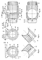
- the connector shown is provided for a plug connection for an electrical connection of motor vehicle trailers. It comprises a housing 10, a rotatable bayonet ring 20 and a cover platform 30 and an intermediate piece 40, e.g. 1a can be seen.
- the lid platform 30 serves to support a can lid 50 when the socket is open. This is with protrusions, e.g. Edge lugs (see FIG. 3d), provided for engagement in corresponding bayonet grooves 22.
- the lid platform 30, the intermediate piece 40 and the bayonet ring 20 are formed in one piece in the illustrated embodiment.
- the bayonet ring 20 is provided with a cam projection 24 which extends radially outward (see FIGS. 1b, 2b).
- the cam projection 24 is clearly recognizable from the outside in the respective position and engages under a corresponding lateral projection in the edge area 52 of the can lid 50 which is formed on the inside with reinforcing ribs 54.
- the cam projection 24 is formed with a sharp-edged nose 26 which engages firmly under the edge area 52 when the bayonet ring 20 is in the locked position.
- the cam projection is provided with a rounded nose 28 for easier unlocking.
- a recess 60 is provided in the bayonet ring 20 as a viewing window on the housing 10.
- the recess 60 releases a label “locked” or “unlocked” depending on the position, so that the respective plug position is easily visible.
- the bayonet ring 20 is firmly connected at the rear end with an aligned cap 62. At the front end it is formed with a neck 64 in which the bayonet grooves 22 are located. At the rear end, the housing 10 carries a rotatable attachment 66, which ensures the sealing of the plug.
- annular disk 70 is arranged between the housing 10 and the bayonet ring 20.
- the washer 70 has a fixed anchoring projection 72 and a resilient projection 74. With the anchoring projection 72, the annular disk 70 firmly engages in a recess or groove 12 in the housing 10.
- the resilient projection 74 protrudes into a recess 68 in the bayonet ring 20, as can best be seen from FIG. 3c.
- a plunger 80 is axially adjustable in the bayonet ring 20. Its head 82 located at the rear end engages with the resilient projection 74 of the annular disk 70.
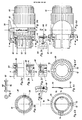
- the plunger is shown in the front position corresponding to the unlocking position of the plug, while the adjustment movement of the plunger 80 is illustrated by means of edge tabs 4 located on the socket neck 2 in Fig. 3d and 3e.
- the resilient projection 74 becomes the ring disk 70 pressed into the plane of the annular disk in such a way that the head 82 of the plunger 80 reaches a rotary groove 14 in the housing 10, in which the head 82 can be guided when the bayonet ring is rotated.
- the rotary groove 14 has a locking lug 16 at the end, to which a locking recess 18 connects.
- the locking recess 18 serves for the engagement of the shaft 84 of the plunger 80 and is aligned with the bayonet catch, ie the bayonet grooves 20.
- a groove 58 is provided for the detent 16.
- FIG. 3a A contact insert 90 with plug contact pins 92 accommodated in the housing 10 is illustrated in FIG. 3a.
- the rotation of the bayonet ring 20 with locking / unlocking is explained below. If the plug is not inserted into the socket, the plug is in the unlocked position. Here, the housing 10 and the bayonet ring 20 are fixed by means of the washer 70, i.e. non-rotatable, connected. If the plug is then inserted into the socket with the cover platform 30 aligned with the socket cover 50, the edge lugs 4 (e.g. 3) provided on the socket neck 2 penetrate into the axial sections of the bayonet grooves 22, at the same time displacing the plunger 80 to the rear. The plunger 80 presses the resilient projection 74 of the ring disk 70 to the rear, so that the bayonet ring 20 and the housing 10 are no longer coupled to one another in a rotationally secure manner.
- the edge lugs 4 e.g. 3
- the shaft 84 of the plunger 80 slides easily over the curved outer surface of the housing 10 until it reaches Latch 16 arrives.
- the shaft 84 can be rotated over the locking lug 16 and snaps into the locking recess 18, as a result of which the plug is additionally locked.
Landscapes
- Details Of Connecting Devices For Male And Female Coupling (AREA)
- Connector Housings Or Holding Contact Members (AREA)
Applications Claiming Priority (2)
| Application Number | Priority Date | Filing Date | Title |
|---|---|---|---|
| DE3830051A DE3830051A1 (de) | 1988-09-03 | 1988-09-03 | Stecker fuer eine steckverbindung |
| DE3830051 | 1988-09-03 |
Publications (3)
| Publication Number | Publication Date |
|---|---|
| EP0358101A2 true EP0358101A2 (fr) | 1990-03-14 |
| EP0358101A3 EP0358101A3 (fr) | 1991-07-24 |
| EP0358101B1 EP0358101B1 (fr) | 1994-11-23 |
Family
ID=6362276
Family Applications (1)
| Application Number | Title | Priority Date | Filing Date |
|---|---|---|---|
| EP89116046A Expired - Lifetime EP0358101B1 (fr) | 1988-09-03 | 1989-08-31 | Fiche pour connexion |
Country Status (3)
| Country | Link |
|---|---|
| EP (1) | EP0358101B1 (fr) |
| AT (1) | ATE114388T1 (fr) |
| DE (2) | DE3830051A1 (fr) |
Cited By (3)
| Publication number | Priority date | Publication date | Assignee | Title |
|---|---|---|---|---|
| EP0585917A3 (en) * | 1992-09-04 | 1996-05-15 | Menber S Spa | A plug for electrical connectors for connection between a towing vehicle and a trailer |
| EP0676831A3 (fr) * | 1994-04-07 | 1997-05-07 | Monika Ruettgerodt | Connecteur, notamment pour la connexion électrique des remorques. |
| US6955834B2 (en) | 2000-06-14 | 2005-10-18 | The Procter & Gamble Company | Long lasting coatings for modifying hard surfaces and processes for applying the same |
Families Citing this family (1)
| Publication number | Priority date | Publication date | Assignee | Title |
|---|---|---|---|---|
| DE4210734A1 (de) * | 1992-04-01 | 1993-10-07 | Lts Lichttechnik Gmbh | Niedervolt-Steckverbinder in koaxialer Bauart |
Family Cites Families (2)
| Publication number | Priority date | Publication date | Assignee | Title |
|---|---|---|---|---|
| US3239791A (en) * | 1964-12-17 | 1966-03-08 | Clas O F Fyrk | Electrical disconnect coupling |
| DE8615641U1 (de) * | 1986-06-10 | 1986-11-13 | Erich Jaeger GmbH & Co KG, 6380 Bad Homburg | Stecker für eine Steckverbindung für den elektrischen Anschluß von Kraftfahrzeuganhängern |
-
1988
- 1988-09-03 DE DE3830051A patent/DE3830051A1/de not_active Withdrawn
-
1989
- 1989-08-31 DE DE58908656T patent/DE58908656D1/de not_active Expired - Fee Related
- 1989-08-31 AT AT89116046T patent/ATE114388T1/de not_active IP Right Cessation
- 1989-08-31 EP EP89116046A patent/EP0358101B1/fr not_active Expired - Lifetime
Cited By (3)
| Publication number | Priority date | Publication date | Assignee | Title |
|---|---|---|---|---|
| EP0585917A3 (en) * | 1992-09-04 | 1996-05-15 | Menber S Spa | A plug for electrical connectors for connection between a towing vehicle and a trailer |
| EP0676831A3 (fr) * | 1994-04-07 | 1997-05-07 | Monika Ruettgerodt | Connecteur, notamment pour la connexion électrique des remorques. |
| US6955834B2 (en) | 2000-06-14 | 2005-10-18 | The Procter & Gamble Company | Long lasting coatings for modifying hard surfaces and processes for applying the same |
Also Published As
| Publication number | Publication date |
|---|---|
| EP0358101B1 (fr) | 1994-11-23 |
| EP0358101A3 (fr) | 1991-07-24 |
| DE3830051A1 (de) | 1990-03-15 |
| DE58908656D1 (de) | 1995-01-05 |
| ATE114388T1 (de) | 1994-12-15 |
Similar Documents
| Publication | Publication Date | Title |
|---|---|---|
| EP0037846B1 (fr) | Dispositif d'ajustement de l'inclinaison d'un clavier | |
| DE1927901A1 (de) | Drehknopf | |
| EP0959978A1 (fr) | Filtre | |
| DE2613013A1 (de) | Absperrbarer verschluss fuer einen mit gewinde versehenen fuellstutzen | |
| DE3405885C1 (de) | Einrichtung zum Befestigen einer Schleifscheibe an der Schleifspindel einer tragbaren Winkelschleifmaschine | |
| DE4409312A1 (de) | Wellenarretiervorrichtung für ein motorisch antreibbares Werkzeug | |
| DE102022121659A1 (de) | Ladesteckdose für ein Elektro- oder Hybridfahrzeug | |
| DE3213773C2 (fr) | ||
| EP0358101B1 (fr) | Fiche pour connexion | |
| DE102020115021A1 (de) | Vorrichtung zum Verbinden zweier röhrenförmiger Objekte | |
| DE2757544C3 (de) | Lenkschloß für Kraftfahrzeuge | |
| DE2715273C2 (de) | Einbauleuchte, insbesondere für Kraftfahrzeuge | |
| DE19603817A1 (de) | Vorrichtung zur Verriegelung eines Containers an einem Fahrzeugchassis | |
| DE102019130176B4 (de) | Steckverbinderteil mit einer Rasteinrichtung | |
| DE102019219497A1 (de) | Manueller trennschalter mit steckverbinderpositionssicherung | |
| EP0215295A1 (fr) | Accouplement pour l'assemblage détachable d'un manche de pièce à main dentaire avec une tête | |
| DE19920864A1 (de) | Thermostatventil-Kopf für Heizkörperventile | |
| DE8811156U1 (de) | Stecker für eine Steckverbindung | |
| DE102024138730B3 (de) | Verfahren zum Demontieren und Montieren eines Bedienteils einer Bedienvorrichtung und Bedienvorrichtung | |
| DE19623405A1 (de) | Stütze zum Halten eines Verschlußelements | |
| DE69202596T2 (de) | Bajonettkupplung. | |
| DE3743557C2 (de) | Befestigungssystem für Gerätesockel | |
| DE2803768C3 (de) | Elektrischer Nockenschalter mit angekuppeltem Drehschalter | |
| DE69303202T2 (de) | Schalter | |
| EP3675981B1 (fr) | Dispositif de fermeture pour un récipient de fluide |
Legal Events
| Date | Code | Title | Description |
|---|---|---|---|
| PUAI | Public reference made under article 153(3) epc to a published international application that has entered the european phase |
Free format text: ORIGINAL CODE: 0009012 |
|
| AK | Designated contracting states |
Kind code of ref document: A2 Designated state(s): AT BE CH DE ES FR GB GR IT LI LU NL SE |
|
| PUAL | Search report despatched |
Free format text: ORIGINAL CODE: 0009013 |
|
| AK | Designated contracting states |
Kind code of ref document: A3 Designated state(s): AT BE CH DE ES FR GB GR IT LI LU NL SE |
|
| 17P | Request for examination filed |
Effective date: 19920115 |
|
| 17Q | First examination report despatched |
Effective date: 19940216 |
|
| GRAA | (expected) grant |
Free format text: ORIGINAL CODE: 0009210 |
|
| AK | Designated contracting states |
Kind code of ref document: B1 Designated state(s): AT BE CH DE ES FR GB GR IT LI LU NL SE |
|
| PG25 | Lapsed in a contracting state [announced via postgrant information from national office to epo] |
Ref country code: ES Free format text: THE PATENT HAS BEEN ANNULLED BY A DECISION OF A NATIONAL AUTHORITY Effective date: 19941123 Ref country code: IT Free format text: LAPSE BECAUSE OF FAILURE TO SUBMIT A TRANSLATION OF THE DESCRIPTION OR TO PAY THE FEE WITHIN THE PRE;WARNING: LAPSES OF ITALIAN PATENTS WITH EFFECTIVE DATE BEFORE 2007 MAY HAVE OCCURRED AT ANY TIME BEFORE 2007. THE CORRECT EFFECTIVE DATE MAY BE DIFFERENT FROM THE ONE RECORDED.SCRIBED TIME-LIMIT Effective date: 19941123 Ref country code: NL Effective date: 19941123 Ref country code: GR Free format text: LAPSE BECAUSE OF FAILURE TO SUBMIT A TRANSLATION OF THE DESCRIPTION OR TO PAY THE FEE WITHIN THE PRESCRIBED TIME-LIMIT Effective date: 19941123 Ref country code: FR Effective date: 19941123 Ref country code: GB Effective date: 19941123 Ref country code: BE Effective date: 19941123 |
|
| REF | Corresponds to: |
Ref document number: 114388 Country of ref document: AT Date of ref document: 19941215 Kind code of ref document: T |
|
| REF | Corresponds to: |
Ref document number: 58908656 Country of ref document: DE Date of ref document: 19950105 |
|
| PG25 | Lapsed in a contracting state [announced via postgrant information from national office to epo] |
Ref country code: SE Effective date: 19950223 |
|
| EN | Fr: translation not filed | ||
| NLV1 | Nl: lapsed or annulled due to failure to fulfill the requirements of art. 29p and 29m of the patents act | ||
| GBV | Gb: ep patent (uk) treated as always having been void in accordance with gb section 77(7)/1977 [no translation filed] |
Effective date: 19941123 |
|
| PG25 | Lapsed in a contracting state [announced via postgrant information from national office to epo] |
Ref country code: LI Effective date: 19950831 Ref country code: AT Effective date: 19950831 Ref country code: CH Effective date: 19950831 Ref country code: LU Free format text: LAPSE BECAUSE OF NON-PAYMENT OF DUE FEES Effective date: 19950831 |
|
| PLBE | No opposition filed within time limit |
Free format text: ORIGINAL CODE: 0009261 |
|
| STAA | Information on the status of an ep patent application or granted ep patent |
Free format text: STATUS: NO OPPOSITION FILED WITHIN TIME LIMIT |
|
| 26N | No opposition filed | ||
| REG | Reference to a national code |
Ref country code: CH Ref legal event code: PL |
|
| PGFP | Annual fee paid to national office [announced via postgrant information from national office to epo] |
Ref country code: DE Payment date: 19980827 Year of fee payment: 10 |
|
| PG25 | Lapsed in a contracting state [announced via postgrant information from national office to epo] |
Ref country code: DE Free format text: LAPSE BECAUSE OF NON-PAYMENT OF DUE FEES Effective date: 20000601 |