EP0358172A2 - Système vidéo muni d'une caméra et d'un dispositif d'enregistrement - Google Patents
Système vidéo muni d'une caméra et d'un dispositif d'enregistrement Download PDFInfo
- Publication number
- EP0358172A2 EP0358172A2 EP89116396A EP89116396A EP0358172A2 EP 0358172 A2 EP0358172 A2 EP 0358172A2 EP 89116396 A EP89116396 A EP 89116396A EP 89116396 A EP89116396 A EP 89116396A EP 0358172 A2 EP0358172 A2 EP 0358172A2
- Authority
- EP
- European Patent Office
- Prior art keywords
- recorder
- camera
- casing
- grip
- recording
- Prior art date
- Legal status (The legal status is an assumption and is not a legal conclusion. Google has not performed a legal analysis and makes no representation as to the accuracy of the status listed.)
- Granted
Links
Images








Classifications
-
- G—PHYSICS
- G11—INFORMATION STORAGE
- G11B—INFORMATION STORAGE BASED ON RELATIVE MOVEMENT BETWEEN RECORD CARRIER AND TRANSDUCER
- G11B31/00—Arrangements for the associated working of recording or reproducing apparatus with related apparatus
- G11B31/006—Arrangements for the associated working of recording or reproducing apparatus with related apparatus with video camera or receiver
-
- H—ELECTRICITY
- H04—ELECTRIC COMMUNICATION TECHNIQUE
- H04N—PICTORIAL COMMUNICATION, e.g. TELEVISION
- H04N23/00—Cameras or camera modules comprising electronic image sensors; Control thereof
- H04N23/50—Constructional details
Definitions
- the present invention relates to a video system, and particularly to a video system which enables integral handling of a camera for converting optical information into electrical signals and a recorder for recording the electrical signals on a recording medium.
- the optical axis of an imaging lens basically intersects at right angles the exposure plane of a film serving as a recording medium.
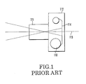
- Fig. 1 shows the general structure of a camera using a silver-halide film as a recording medium.
- the image of a subject projected from a camera lens 111 is recorded on the exposure plane of a film 114 which is disposed so as to intersect at right angles an optical axis 115.
- a camera body 12 In such an arrangement in which the exposure plane of the film 114 is disposed so as to intersect at right angles the optical axis, a camera body 12 must be disposed as shown in Fig. 2 for the purpose of properly receiving a film cartridge 113 in the space.
- the widest end surface of the camera body 112 intersects the optical axis at right angles.
- the structures are basically the same as the above-mentioned structure so long as the exposure plane of a film is caused to intersect the optical axis.
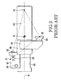
- Fig. 2 shows the configuration of a so-called shoulder type of integral VTR.
- reference numeral G1 denotes the center of gravity of the apparatus; reference numeral Y1, the optical axis; reference numeral 101, a grip; reference numeral 102, a lens unit; a reference numeral 103, a camera part; reference numeral 104, an electronic viewfinder (EVF) part; and reference numeral 105, a recorder part.
- the switches shown in Fig. 2 include a recording trigger switch 133, a recording trigger switch for low angles 136 and a zoom switch 138.
- Fig. 3 shows an example in which the integral VTR shown in Fig. 2 is held during photography at a normal angle.
- this sort of shoulder-type integral VTR is surely and stably held at three points, such as a right-hand support point p1 in the grip part 101, an ocular support point p3 in the ocular part of the EVF part 104 and a shoulder support point p2 in the recorder part 105.
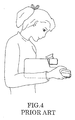
- Fig. 4 shows an example in which the integral VTR shown in Fig. 2 is held during photography at a low angle.
- the apparatus is in a holding style in which the grip part 101 and the recorder part 105 are immobilized with both hands.
- the recording trigger switch 133 cannot be easily operated, the low angle recording trigger switch 136 is operated.
- the shoulder-type integral VTR shown in Fig. 2 can be surely and stably held, since the distance between the shoulder support point p2 and the ocular support point p3 is inevitably determined by the distance between the eyes and the shoulder of a human, no attempt can be made to reduce the overall size of the apparatus.
- the right hand by which the grip part 101 is held on the upper side thereof must be used for operating the low angle trigger switch 136, the holding becomes unstable each time the switch 136 is operated with the right hand.
- Figs. 5(A) and 5(B) show the most general structure of a one-hand type of integral VTR.
- Fig. 5(A) is a left-hand side view
- Fig. 5(B) is a right-hand side view.
- reference numeral 151 denotes a lens unit for holding and driving a lens group serving as a photo-taking optical system
- reference numeral 152 a camera part for converting optical information injected through the lens group in the lens unit 151 into electrical video signals
- reference numeral 153 a recorder part for recording the video signals from the camera part 152 on a magnetic tape.
- the lens unit 151, the camera part 152 and the recorder part 153 are generally disposed on a line.
- Reference numeral 154 denotes an electronic viewfinder (EVF) part for displaying the video signals recorded in the recorder part 153
- reference numeral 155 denotes a grip for allowing a photographer to hold the integral VTR.
- EMF electronic viewfinder
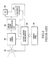
- the configuration of the integral VTR is outlined below with reference to Fig. 6.
- the light-receiving face of an image sensor 202 in the camera part 152 should be caused to intersect the optical axis of the lens unit 151.
- the image of a subject is formed on the image sensor 202 through the lens group in the lens unit 151.
- the electrical signal corresponding to the image of the subject is output from the image sensor 202 and then supplied to a camera signal processing circuit 203.
- the circuit 203 converts the electrical signal into an image signal in a given form and then outputs it.
- the image signal output from the circuit 203 is electrically supplied to a recorder 205 and a EVF 204 and is recorded on the magnetic tape in the recorder 205 and displayed as a visible image on the display in the EVF 204.
- the photographer operates a console panel 207 while confirming the image to be photographed by the EVF 204.
- the data indicating the contents of operation by the console panel 207 is broken down into commands indicating the contents of specific processing by a microcomputer 206 for system control and is then supplied to each of the parts.
- at least instructions to start recording and finish recording are given to the recorder 205 which thus serves to record the above-described image signal when receiving the instructions.
- the recorder 205 and the EVF 204 shown in Fig. 6 are contained in the recorder part 153 and the EVF part 154, respectively, as shown in Figs. 5(A) and 5(B).
- the integral VTR enables the structure and arrangement of the respective parts to be freely determined except for the direction of the light-receiving face of the image sensor 202 and thus has a higher degree of structural freedom than cameras using silve-halide films.
- conventional integral VTRs do not make sufficient use of such a high degree of freedom and have anything but an optimum structure in the sense of human engineering.
- the integral VTR shown in Figs. 5(A) and 5(B) involves the following disadvantages:
- Fig. 7 is a diagram for explaining a first problem of the integral VTR shown in Figs. 5(A) and 5(B).
- the integral VTR shown in Figs. 5(A) and 5(B) since the distance between the grip 155 and the ocular part of the EVF part 154 is large, the angles ⁇ 1 and ⁇ 2 are increased, as shown in Fig. 7. This makes stable holding impossible.
- the angles ⁇ 1 and ⁇ 2 are further increased owing to the necessity to increase the distance between the recorder 153 and the ocular part of the EVF part 154 in order to relieve the cramped feeling given to the photographer and because of contact of the recorder part 153 with the nose of the photographer, which are caused by the arrangement in which the recorder part 153 is disposed near the front of the photographer.
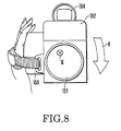
- Fig. 8 is a diagram for explaining a second problem of the integral VTR shown in Figs. 5(A) and 5(B) in which the same reference numerals as those in Figs. 5(A) and 5(B) are used.
- Fig. 8 is a front view of the integral VTR shown in Figs. 5(A) and 5(B), the mark x in the figure representing the center of gravity of the integral VTR.
- a force is exerted on the wrist of the photographer in the direction shown by the arrow V. This force corresponds to a force to inwardly bend the wrist of the photographer and thus creates a great load on the photographer and inhibits stable holding.
- Fig. 9 shows the upper surface of a more specific example of the arrangement of the integral VTR shown in Figs. 5(A) and 5(B).
- reference numeral G2 denotes the center of gravity of the apparatus; reference numerals X2, Y2, axes which intersect each other at the center of gravity G2; reference numeral Y3, the optical axis; reference numeral 134, a recording trigger switch; reference numeral 137, a low-angle recording trigger switch; and reference numeral 139, a zoom trigger switch.
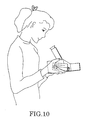
- Fig. 10 shows an example in which the integral VTR shown in Fig. 9 is held during low-angle photography.
- the apparatus is also in a holding style in which the grip part 155 and the recorder part 153 are immobilized with the both hands.
- the normal recording trigger switch 134 cannot be easily operated, the low-angle recording trigger switch 137 is employed.
- the left hand support point p6 is used during telephotography, the above-mentioned holding method which depends upon the point p6 is easily influenced by the movement of the hands caused by the moments which are produced in the directions shown by the arrow y and the arrow x.
- the integral VTR also involves problems with respect to unstable holding caused by the need to use the eye-level grip 155 and by the operation of the recording trigger switch 137 and the difficulty in operation of the zoom switch 139, these problems being the same as those of the above-mentioned shoulder-type integral VTR.
- the present invention provides as an embodiment a video system comprising a photographic optical system, a camera for converting optical information obtained from the photographic optical system into an electrical signal and a recorder for recording the electrical signal on a recording medium, wherein the system has a recorder casing in which a part of the recorder is housed and wherein the lengthwise direction of the recorder casing is arranged to be oblique with respect to an optical axis of the optical system on a plane that is horizontal during photography by the camera.
- the present invention provides as another embodiment a video system comprising a photographic optical system, a camera for converting optical information obtained from the photographic optical system into an electrical signal and a recorder for recording the electrical signal on a recording medium, wherein the system has camera casing for housing a part of the camera and a recorder casing in which a part of the recorder is housed and which is disposed along a plane intersecting an optical axis of the optical system, the camera casing being provided with a first grip for holding the system, and the recording casing being provided with a second grip for holding the system.
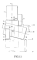
- FIG. 11 is schematic top views of the camera-integrated VTRs in which reference numeral 1 denotes a lens unit; reference numeral 2, a camera casing; and reference numeral 3, a recorder casing. As shown in Fig.
- the recorder casing 3 is disposed at an oblique angle in the lengthwise direction (shown by a one-dot chain line z in the figure) with respect to an optical axis (shown by a one-dot chain line x in the figure) of the lens unit 1 on a horizontal plane during photography. Since the image sensor in the camera casing 2 is so disposed as to intersect the optical axis x at right angles, the arrangement itself is the same as that of the conventional VTR shown in Fig. 6.
- Such a disposal of the recorder casing 3 enables the resolution of the various problems of conventional VTRs.
- an ocular part 41 is placed near a grip 5.
- the center of gravity is moved from G1 to G2, and the grip 5 is also moved in response to the movement of the center of gravity.
- the ocular part 41 is moved from l1 to l2 while the grip 5 is moved from l3 to l4. Since the distance of movement of the ocular part 41 is smaller than that of the grip 5, the distance between the ocular part 41 and the grip 5 is consequently reduced.
- the EVF part 4 in the state where the optical axis x is at an oblique angle with respect to the lengthwise direction z of the recorder casing 3, as described above, the EVF part 4 is provided in a portion between the optical axis x and the subject-side end 3a (the left side of the figure) of the recorder casing 3. Consequently, the ocular part 41 of the EVF part 4 is further approached to the grip 5 in the direction of the optical axis x.
- the center of gravity of the recorder casing 3 is positioned between the optical axis x and the photographer-side end 3b of the recorder casing 3, the center of gravity of the whole of the VTR approaches the photographer side, whereby the grip 5 can be further approached to the ocular part 41 in the direction of the optical axis x.
- the grip 5 is separated from the ocular part 41 in the direction intersecting the optical axis x at right angles, the distance between the grip 5 and the ocular part 41 in this direction is close to the distance between the positions of the eyes and the shoulder in the same direction and is thus rather preferable.
- the center of gravity of the recorder casing 3 is positioned between the optical axis x and the photographer-side end 3b of the recorder casing 3 so that the center of gravity of the whole of the VTR approaches the side of the grip 5. It is therefore possible to reduce the force exerting in the direction shown by the arrow V in Fig. 8 and reduce the load on the photographer.
- Fig. 12 is a top view of a camera-integrated VTR in an embodiment of the present invention and Figs. 13 and 14 are a side view and a rear view, respectively, of the same.
- a trigger switch 31 for instructing to start and end photography
- a telephoto indicating switch 33T for changing angles of view of the lens unit 1
- a wide-angle indicating switch 33W for changing angles of view of the lens unit 1
- the recorder casing 3 has a switch panel (console panel) 32 in which are provided a fast-forward button 321, a reproduction button 322, a rewind button 323, a stop button 324 and a picture recording button 325.
- the indications of these switches are transmitted to a control microcomputer through electrical processing which is the same as in conventional apparatuses so as to control the respective parts of the VTR.
- a lower cover 11 of the lens unit 1 in a lower cover 11 of the lens unit 1 are disposed lens driving actuators for adjusting the focus, the angle of view (focal length) and so on.
- reference numeral 34 denotes a mounting part for a video tape cassette, the EVF part 4 and the eye-cup 41 serving as the ocular part of the EVF part 4 being positioned above this.
- an optical finder using EVF is used as a finder also enables the same effect to be expected.
- the finder is preferably disposed near the optical axis because the optical path cannot easily be set if the finder is so disposed as to significantly deviate from the optical axis.
- an apparatus having a camera casing and a recorder casing which are common with each other can also exhibit the same effect if the common casing is disposed at an oblique angle with the optical axis in the lengthwise direction on the horizontal plane.
- the present invention is effective for the application to an apparatus which is handled in a state where the recorder part is combined with the camera part containing the lens unit at least during photography.
- the above-mentioned embodiment concerns an the camera-integrated VTR as an example in which the magnetic tape is used as a recording medium
- the application of the present invention to a so-called electronic still camera for recording still pictures using a magnetic floppy disk can also exhibit the same effect.
- the camera-integrated VTR shown in Figs. 11 to 14 has a structure which is excellent in the sense of human engineering, and particularly enables stable holding and good photography without camera shake.
- Fig. 15 is a schematic top view of an integral VTR in another embodiment of the present invention.
- reference numeral 71 denotes a first grip
- reference numeral 72 a second drip
- reference numeral 73 a lens unit
- reference numeral 74 a camera casing
- reference numeral 75 a recorder casing
- reference numeral 76 an EVF part
- reference numeral G3 the center of gravity
- reference numeral Y4 the optical axis
- reference numeral Y5 a line passing through the center of gravity and parallel with the optical axis.
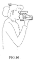
- the integral VTR shown in Fig. 15 can be held only by the right hand with which the first grip is held in the same manner as in conventional one-hand types of integral VTR, as shown in Fig. 16.
- the recorder casing 75 is disposed along a plane intersecting the optical axis Y4 so that the entire length in the direction of the optical axis Y4 is reduced, whereby the distance in the direction of the optical axis between the grip 71 and the ocular part 80 of the EVF part 76 can be reduced, and thus the photographer can stably hold the VTR with closing the armpits.
- the center of gravity approaches the first grip 71. Since the recorder casing 75 is also disposed to be inclined so that the side of the recorder casing 75 near the first grip 71 is placed far from the subject, the degree of freedom of the position in which the first grip 71 is mounted is high so that the first grip 71 can be mounted near the center of gravity G3.
- Fig. 16 shows an example in which the integral VTR shown in Fig. 15 is held only by the right hand, as shown in Fig. 16.
- FIG. 17 shows an example in which the integral VTR shown in Fig. 15 is held by using the second grip 72.
- the VTR can be extremely stably held by the right hand in the second grip 72, the left hand in a lower portion of the lens unit 73 and the ocular part 80, i.e., at the three points p7, p8, p9 shown in Fig. 15.
- the center of gravity G3 is close to the line segment connecting the supporting point p7 by the right hand and the supporting point p8 by the left hand, and a small shift produces such a moment that can be compensated for by the presence of the supporting point p9, resulting in extremely stable holding.
- Such holding using the second grip 72 is particularly effective for, for example, telephotography in which the camera shake has a significant effect.
- only a short time is taken to switch the state where the integral VTR is released from the holding during non-photography to the holding state shown in Fig. 17, and there is no need to put the hand into the grip strap from the lower side of the apparatus, as conventional integral VTRs.
- the integral VTR is therefore excellent in its snapshooting properties and is particularly effective to the case of photography for several seconds.
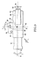
- Fig. 19 is a detailed top view of the integral VTR shown in Fig. 15 and Figs. 20 and 21 are a rear view and a side view of the same.
- the same parts as those in Fig. 15 are denoted by the same reverence numerals.
- reference numeral 81 denotes a recording trigger switch of the first grip 71 and reference numeral 83 denotes a zoom ratio-changing switch of the first grip 71.
- reference numeral 82 denotes a recording trigger switch of the second grip 72 and reference numeral 84 denotes a zoom ratio-changing switch of the second grip 72.
- the provision of the recording trigger switches and the zoom ratio-changing switches corresponding to the first grip 71 and the second grip 72 enables the start and stop of the recording and the changing-over of zoom ratios in either low-angle or eye-level photography, without the position of the right hand being changed, and this provision thus enables good photography.
- reference numeral 85 denotes a fast-forward button
- reference numeral 86 a reproduction button
- reference numeral 87 a fast-rewind button
- reference numeral 88 a stop button
- reference numeral 89 a picture recording button, which are all known in conventional VTRs.
- reference numeral 90 denotes a cassette cover which is closed and opened for the purpose of loading a tape cassette
- reference numeral 91 a cassette window which is provided so that the cassette loaded can be seen from the outside
- reference numeral 92 a tripod socket.
- the integral VTR of this embodiment enables framing by holding the second grip 72 with the right hand even in the case of photography by the VTR mounted on a tripod using the tripod socket 92, as well as enabling the operation of trigger switch 82 and the zoom ratio-changing switch 84 without the right hand being moved, resulting in an improvement in the operational properties in the use of a tripod.
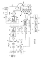
- the light from a subject 181 passes through a lens unit 182 and forms an image on an image sensor 183.
- the electrical signals output from the image sensor 183 are converted into television signals by a camera signal processing circuit 184.
- Reference numeral 185 denotes an automatic white balance adjusting (AWB) circuit; reference numeral 186, an automatic exposure adjusting (AE) circuit; and reference numeral 187, an automatic focusing (AF) circuit.
- ABB white balance adjusting
- AE automatic exposure adjusting
- AF automatic focusing
- the AWB signal is returned to the camera signal processing circuit 184 so as to control the balance of the gains of color signals.
- the AE signal is input to a driver 188 which drives an IG meter 189 so as to control a diaphragm adjusting mechanism 182-c of the lens unit 182 to appropriate exposure.
- the AF signal is input to a driver 172 which drives a focus motor 173 so as to control a focusing optical system 182-a of the lens unit 182 to a focused state.
- the thus-controlled television signals output from the camera part are converted into recording signals by a recorder signal processing circuit 174 and then recorded in turn on a magnetic tape 280 by rotary heads 176-a, 176-b on a rotary cylinder 177 through a switch circuit 175.
- the magnetic tape 280 is carried by a capstan 178 and a pinch roller 179.
- the capstan 178 is driven by a capstan motor 284, and the rotational speed thereof is detected by a capstan frequency detector (FG) 285 and controlled by a servo circuit 286.
- the rotary cylinder 177 on which the rotary heads 176-a, 176 b, 176-c are fixed is driven by a cylinder motor 281, and the rotational speed and the rotational phase thereof are detected by a cylinder frequency detector (FG) 283 and a cylinder phase detector (PG) 282, respectively, and are controlled by the servo circuit 286.
- FG cylinder frequency detector
- PG cylinder phase detector
- the servo circuit 286 supplies to the switch 175 a head switching signal synchronizing with the cylinder PG signal so that the switching of the switch 175 is controlled.
- the servo circuit 286 serves to control the motors 281 and 284 in accordance with the modes determined by the system controller 290.
- a character generator 287 supplies to an adder 289 a character signal indicating the mode which is determined by the system controller 290.
- a switch 288 is connected to the R side during recording and to the P side during reproduction so that the television signal from the camera signal processing circuit 184 and the reproduced television signal from the recorder signal processing circuit 174 are supplied to the adder 289 during recording and reproduction, respectively.
- the output from the adder 289 is supplied to an EVF 270 so that the image photographed or the image reproduced, on which the characters are superposed, is displayed through a magnifying optical system 271.
- the magnifying optical system 271 makes photographic framing visible without bringing the eyes into contact with the ocular part 80 particularly for the purpose of enabling low-angle photography by the apparatus which is held as shown in Fig. 18.
- An operation part A 291 contains the recording trigger switch 81 and the zoom ratio-changing switch 83 shown in Figs. 19 to 21 and supplies to the system controller 290 a binary signal indicating whether or not the recording trigger switch 81 is turned on, a binary signal indicating whether or not the telephoto (T) side of the zoom ratio-changing switch 83 is turned on, and a binary signal indicating whether or not the wide-angle (W) side thereof is turned on.
- An operation part B 292 contains the recording trigger switch 82 and the zoom ratio-changing switch 84 and supplies the same three binary signals to the system controller 290.
- An operation part C 293 supplies to the system controller 290 five binary signals which respectively indicate whether or not the buttons 85 to 89 shown in Fig. 19 are turned on.
- the system controller 290 drives the motor 171 by using the driver 170 so that a variable power optical system 182-b is moved to the telephoto side. If the W side of the switch 83 or 84 is turned on, the system controller 290 drives the motor 171 in the same manner as that described above so that the variable power optical system 182-b is moved to the wide-angle side. If the T side of one of the switches 83 and 84 is turned on and the W side of the other is turned on, the operation is performed in accordance with the operation of the switch 83 which is not easily brought into contact with the human bodies.
- the system controller 290 is switched to the modes in accordance with the operations of the buttons 85 to 89 in the operation part C 293.
- the system controller 290 switches the switch 288 to the R side so as to cause the cylinder motor 281 and the capstan motor 284 to rotate by using the servo circuit 286 to bring about a recording stand-by state for standing by until the pinch roller 179 is attached to the capstan 178.
- the recording stand-by state if the recording trigger switch on the side of the first grip 71 is turned on, the binary signal output from the operation part A 291 to the system controller 290 is at a high level indicating that the switch 28 is turned on, as shown by A-1 in Fig. 23 and, accordingly, the stem controller 290 causes the pinch roller 179 to attach to the capstan 178 to bring about a recording state.
- the switch 81 is again turned on, the recording state returns to the recording stand-by sate.
- the system controller 290 causes the pinch roller 179 to attach to the capstan 178 only during the time of the on-state to bring about a recording state, as shown by B-1 and B-2 in Fig. 23, and the recording sate returns to the recording stand-by state when the switch 82 is turned off.
- the system controller 290 switches the switch 288 to the P side and outputs the reproduced television signal, as well as displaying it in the EVF 270.
- the pinch roller 179 is then pressed to abut on the capstan 178 to create a reproduction state.
- the system controller 290 causes the capstan motor 284 to stop so as to bring the apparatus in a still picture reproduction state.
- the recording trigger switch 82 is again turned on, the capstan motor 284 is driven to return this sate to the reproduction state.
- the trigger switch 82 on the side of the second grip 72 is disposed on the same surface as the operational buttons 85 to 89, the number of the necessary buttons can be reduced by using the switch 82 also as a still picture reproduction button.
- the camera-integrated VTR of the embodiment shown in Figs. 15 to 23 enables stable photography by using the grip 71 which is disposed near the center of gravity during one-hand photography and extremely stable holding by using the grip 72 during telephotography or photography for a short time.
- the use of the grip 72 enables stable low-angle photography and switching of angles.
- the recording trigger switch and the zoom ratio-changing switch are provided for each of the grips, the operation can be easily performed in any photographic state.
- the camera-integrated VTR shown in Figs. 15 to 23 enables stable holding in any desired photographic state and the reduction in the size of the apparatus itself.
- a video system enables integral handling of a camera for converting optical information obtained from a photographic optical system into electrical signals and a recorder for recording the electrical signals on a recording medium, and is characterized in that the lengthwise direction of the recorder casing housing at least part of the recorder is disposed at an oblique angle with respect to an optical axis of the optical system on a horizontal plane during photography by the camera.
Landscapes
- Engineering & Computer Science (AREA)
- Multimedia (AREA)
- Signal Processing (AREA)
- Accessories Of Cameras (AREA)
- Studio Devices (AREA)
- Viewfinders (AREA)
Applications Claiming Priority (4)
| Application Number | Priority Date | Filing Date | Title |
|---|---|---|---|
| JP118676/88U | 1988-09-08 | ||
| JP1988118676U JPH0733492Y2 (ja) | 1988-09-08 | 1988-09-08 | カメラ付レコーダ |
| JP157189/88U | 1988-11-30 | ||
| JP1988157189U JPH0646128Y2 (ja) | 1988-11-30 | 1988-11-30 | カメラ付レコーダ |
Publications (3)
| Publication Number | Publication Date |
|---|---|
| EP0358172A2 true EP0358172A2 (fr) | 1990-03-14 |
| EP0358172A3 EP0358172A3 (en) | 1990-09-26 |
| EP0358172B1 EP0358172B1 (fr) | 1994-06-08 |
Family
ID=26456574
Family Applications (1)
| Application Number | Title | Priority Date | Filing Date |
|---|---|---|---|
| EP89116396A Expired - Lifetime EP0358172B1 (fr) | 1988-09-08 | 1989-09-05 | Système vidéo muni d'une caméra et d'un dispositif d'enregistrement |
Country Status (2)
| Country | Link |
|---|---|
| EP (1) | EP0358172B1 (fr) |
| DE (1) | DE68915907T2 (fr) |
Cited By (2)
| Publication number | Priority date | Publication date | Assignee | Title |
|---|---|---|---|---|
| EP0466162A1 (fr) * | 1990-07-13 | 1992-01-15 | Matsushita Electric Industrial Co., Ltd. | Enregistreur d'images |
| US5523784A (en) * | 1990-02-01 | 1996-06-04 | Canon Kabushiki Kaisha | Electronic still camera which allows a second operation to be performed regardless of the state of a first operation |
-
1989
- 1989-09-05 EP EP89116396A patent/EP0358172B1/fr not_active Expired - Lifetime
- 1989-09-05 DE DE68915907T patent/DE68915907T2/de not_active Expired - Fee Related
Cited By (3)
| Publication number | Priority date | Publication date | Assignee | Title |
|---|---|---|---|---|
| US5523784A (en) * | 1990-02-01 | 1996-06-04 | Canon Kabushiki Kaisha | Electronic still camera which allows a second operation to be performed regardless of the state of a first operation |
| US5612737A (en) * | 1990-02-01 | 1997-03-18 | Canon Kabushiki Kaisha | Electronic still camera with temporarily halting and restarting of optical system control |
| EP0466162A1 (fr) * | 1990-07-13 | 1992-01-15 | Matsushita Electric Industrial Co., Ltd. | Enregistreur d'images |
Also Published As
| Publication number | Publication date |
|---|---|
| EP0358172A3 (en) | 1990-09-26 |
| DE68915907T2 (de) | 1995-01-19 |
| EP0358172B1 (fr) | 1994-06-08 |
| DE68915907D1 (de) | 1994-07-14 |
Similar Documents
| Publication | Publication Date | Title |
|---|---|---|
| US5940641A (en) | Extending panoramic images | |
| JPS62159577A (ja) | 電子スチル・カメラ・ユニツト | |
| JP2000101879A (ja) | 撮像装置 | |
| US4739417A (en) | Multi-mode electronic camera | |
| JPH0368916A (ja) | カメラの画像動揺補正装置 | |
| JPH03235491A (ja) | 記録再生機能付双眼鏡 | |
| EP0358172B1 (fr) | Système vidéo muni d'une caméra et d'un dispositif d'enregistrement | |
| JP2554110Y2 (ja) | カメラ | |
| US5657083A (en) | Video camera having parts arranged to reduce affects of shake | |
| JPH0297175A (ja) | スチルビデオ装置 | |
| KR100209902B1 (ko) | 스틸카메라일체형비데오카메라 | |
| KR100209906B1 (ko) | 스틸카메라일체형비데오카메라 | |
| JPH0646128Y2 (ja) | カメラ付レコーダ | |
| JPH1023363A (ja) | 映像撮影装置 | |
| JP2852224B2 (ja) | スチルカメラ一体型ビデオカメラ | |
| JP2852223B2 (ja) | スチルカメラ一体型ビデオカメラ | |
| KR100209905B1 (ko) | 스틸카메라일체형비데오카메라 | |
| KR100209907B1 (ko) | 스틸카메라일체형비데오카메라 | |
| JPH0733492Y2 (ja) | カメラ付レコーダ | |
| JP2950751B2 (ja) | スチルカメラ一体型ビデオカメラ | |
| US20050285964A1 (en) | Image pickup apparatus having a display panel | |
| JP2832932B2 (ja) | 自動焦点制御装置 | |
| EP0559325A1 (fr) | Appareil photographique | |
| JPH0199379A (ja) | ムービーカメラ装置 | |
| JPH0933985A (ja) | 複合カメラ |
Legal Events
| Date | Code | Title | Description |
|---|---|---|---|
| PUAI | Public reference made under article 153(3) epc to a published international application that has entered the european phase |
Free format text: ORIGINAL CODE: 0009012 |
|
| AK | Designated contracting states |
Kind code of ref document: A2 Designated state(s): DE FR GB IT NL |
|
| PUAL | Search report despatched |
Free format text: ORIGINAL CODE: 0009013 |
|
| AK | Designated contracting states |
Kind code of ref document: A3 Designated state(s): DE FR GB IT NL |
|
| 17P | Request for examination filed |
Effective date: 19901221 |
|
| 17Q | First examination report despatched |
Effective date: 19921105 |
|
| GRAA | (expected) grant |
Free format text: ORIGINAL CODE: 0009210 |
|
| AK | Designated contracting states |
Kind code of ref document: B1 Designated state(s): DE FR GB IT NL |
|
| PG25 | Lapsed in a contracting state [announced via postgrant information from national office to epo] |
Ref country code: IT Free format text: LAPSE BECAUSE OF FAILURE TO SUBMIT A TRANSLATION OF THE DESCRIPTION OR TO PAY THE FEE WITHIN THE PRE;WARNING: LAPSES OF ITALIAN PATENTS WITH EFFECTIVE DATE BEFORE 2007 MAY HAVE OCCURRED AT ANY TIME BEFORE 2007. THE CORRECT EFFECTIVE DATE MAY BE DIFFERENT FROM THE ONE RECORDED.SCRIBED TIME-LIMIT Effective date: 19940608 Ref country code: FR Effective date: 19940608 |
|
| REF | Corresponds to: |
Ref document number: 68915907 Country of ref document: DE Date of ref document: 19940714 |
|
| EN | Fr: translation not filed | ||
| PLBE | No opposition filed within time limit |
Free format text: ORIGINAL CODE: 0009261 |
|
| STAA | Information on the status of an ep patent application or granted ep patent |
Free format text: STATUS: NO OPPOSITION FILED WITHIN TIME LIMIT |
|
| 26N | No opposition filed | ||
| REG | Reference to a national code |
Ref country code: GB Ref legal event code: IF02 |
|
| PGFP | Annual fee paid to national office [announced via postgrant information from national office to epo] |
Ref country code: DE Payment date: 20070830 Year of fee payment: 19 |
|
| PGFP | Annual fee paid to national office [announced via postgrant information from national office to epo] |
Ref country code: GB Payment date: 20070905 Year of fee payment: 19 |
|
| PGFP | Annual fee paid to national office [announced via postgrant information from national office to epo] |
Ref country code: NL Payment date: 20070916 Year of fee payment: 19 |
|
| GBPC | Gb: european patent ceased through non-payment of renewal fee |
Effective date: 20080905 |
|
| PG25 | Lapsed in a contracting state [announced via postgrant information from national office to epo] |
Ref country code: NL Free format text: LAPSE BECAUSE OF NON-PAYMENT OF DUE FEES Effective date: 20090401 |
|
| NLV4 | Nl: lapsed or anulled due to non-payment of the annual fee |
Effective date: 20090401 |
|
| PG25 | Lapsed in a contracting state [announced via postgrant information from national office to epo] |
Ref country code: DE Free format text: LAPSE BECAUSE OF NON-PAYMENT OF DUE FEES Effective date: 20090401 |
|
| PG25 | Lapsed in a contracting state [announced via postgrant information from national office to epo] |
Ref country code: GB Free format text: LAPSE BECAUSE OF NON-PAYMENT OF DUE FEES Effective date: 20080905 |