EP0466162A1 - Enregistreur d'images - Google Patents
Enregistreur d'images Download PDFInfo
- Publication number
- EP0466162A1 EP0466162A1 EP91111585A EP91111585A EP0466162A1 EP 0466162 A1 EP0466162 A1 EP 0466162A1 EP 91111585 A EP91111585 A EP 91111585A EP 91111585 A EP91111585 A EP 91111585A EP 0466162 A1 EP0466162 A1 EP 0466162A1
- Authority
- EP
- European Patent Office
- Prior art keywords
- recording
- imaging device
- disc
- scanning frequency
- processing circuit
- Prior art date
- Legal status (The legal status is an assumption and is not a legal conclusion. Google has not performed a legal analysis and makes no representation as to the accuracy of the status listed.)
- Withdrawn
Links
Images

Classifications
-
- H—ELECTRICITY
- H04—ELECTRIC COMMUNICATION TECHNIQUE
- H04N—PICTORIAL COMMUNICATION, e.g. TELEVISION
- H04N5/00—Details of television systems
- H04N5/76—Television signal recording
- H04N5/765—Interface circuits between an apparatus for recording and another apparatus
- H04N5/77—Interface circuits between an apparatus for recording and another apparatus between a recording apparatus and a television camera
-
- H—ELECTRICITY
- H04—ELECTRIC COMMUNICATION TECHNIQUE
- H04N—PICTORIAL COMMUNICATION, e.g. TELEVISION
- H04N1/00—Scanning, transmission or reproduction of documents or the like, e.g. facsimile transmission; Details thereof
- H04N1/21—Intermediate information storage
- H04N1/2104—Intermediate information storage for one or a few pictures
- H04N1/2112—Intermediate information storage for one or a few pictures using still video cameras
-
- H—ELECTRICITY
- H04—ELECTRIC COMMUNICATION TECHNIQUE
- H04N—PICTORIAL COMMUNICATION, e.g. TELEVISION
- H04N25/00—Circuitry of solid-state image sensors [SSIS]; Control thereof
-
- H—ELECTRICITY
- H04—ELECTRIC COMMUNICATION TECHNIQUE
- H04N—PICTORIAL COMMUNICATION, e.g. TELEVISION
- H04N2101/00—Still video cameras
Definitions
- the present invention relates to an image recording apparatus for recording a videoed picture signal on a recording medium such as, for example, a magnetic recording disc, an optical recording disc or a magneto-optical recording disc.
- a recording medium such as, for example, a magnetic recording disc, an optical recording disc or a magneto-optical recording disc.
- the scanning frequency of an imaging device or tube can be driven at a scanning frequency of a standard television system which may be a vertical scanning frequency of 60 Hz in the case of the NTSC television scheme or a vertical scanning frequency of 50 Hz in the case of the PAL television scheme thereby to enable a video signal to be recorded on a recording medium, for example, a magnetic recording tape or any one of the various discs, in synchronism with this frequency.
- a standard television system which may be a vertical scanning frequency of 60 Hz in the case of the NTSC television scheme or a vertical scanning frequency of 50 Hz in the case of the PAL television scheme thereby to enable a video signal to be recorded on a recording medium, for example, a magnetic recording tape or any one of the various discs, in synchronism with this frequency.
- a recording medium for example, a magnetic recording tape or any one of the various discs
- the scanning frequency of an imaging device or tube is driven at the scanning frequency of a standard television system thereby to enable a video signal to be recorded on a recording medium in synchronism with this frequency.
- the number of the heads employed, the tape wrap angle at which a length of magnetic tape is turned around the cylinder and the number of revolutions of the cylinder are all required to be increased, increasing a load on the recording means.
- the disc for use in a disc apparatus is to be reduced in size, the number of turn of the disc and the recording capacity are required to be increased and reduced, respectively, and a reduction in size of the recording medium requires the use of a highly precise recording means. In either case, it is difficult to accomplish a reduction in size and also in manufacturing cost.
- the present invention has therefore been devised with a view to substantially eliminating the above discussed problems inherent in the prior art image recording apparatuses and is intended to provide an improved image recording apparatus which can be manufactured compact in size and at a reduced manufacturing cost without increasing the load on the recording means and the signal processing circuit and which is effective to provide high quality images.
- an image recording apparatus comprises an imaging device, a drive circuit for driving the imaging device, a signal processing circuit for processing an output signal from the imaging device, and a recording means for recording an output signal from the signal processing circuit on a recording medium.
- the imaging device has a scanning frequency which is lower than a scanning frequency of a standard TV system at least during a recording operation.
- the scanning frequency of the imaging device is chosen to be lower than that of the standard TV system, the signal processing speed can be lowered enough to reduce the load on the circuit as a whole, making it possible to reduce the manufacturing cost of the image recording apparatus.
- the recording means is driven at a standard or ordinary speed, the amount of information to be recorded on a single track can be reduced, making it possible to maintain the recording wavelength even if the image recording apparatus is made compact, with no image quality reduced.
- both of the cylinder and the recording medium can be reduced in size and, therefore, a reduction in both size and power of the recording means as a whole can be accomplished, leading to a reduction in manufacturing cost.
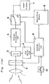
- Fig. 1(a) illustrates a schematic circuit block diagram of an image recording apparatus embodying the present invention
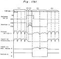
- Fig. 1(b) illustrates waveforms of various functional devices in the image recording apparatus shown in timed relationship.
- Fig. 1(a) imagewise rays of light entering an objective lens assembly 1 fall on a charge-coupled device (CCD) 3 through a shutter 2.
- the charge-coupled device 3 is driven by a CCD drive circuit 4, and an output signal emerging from the charge-coupled device 3 is supplied to a signal processing circuit 5.
- An output from the signal processing circuit 5 is supplied to a changeover switch 6 having a movable contact engageable selectively with fixed contacts V and R which are electrically connected with a viewfinder 7 and a recording means 8, respectively, the position of said movable contact of the changeover switch 6 being controlled by a command issued from a system control circuit 9.
- the recording means 8 referred to above may be a video tape recorder, a magnetic disc device, an optical disc device, a magneto-optical disc device or any other suitable recording device.
- the system control circuit 8 equally controls the shutter 2, the CCD drive circuit 4 and the recording means 8.
- Reference numeral 10 represents a release switch.
- a signal to be recorded is a standard TV signal based on the NTSC scheme known to those skilled in the art.
- the shutter 2 may be of a construction comprising a plurality of mechanical blades or diaphragms, or it may be in the form of a spatial light modulating device such as a liquid crystal shutter. In either case, the shutter 2 is preferred to have a high speed response, an excellent light shielding property and a sufficient durability.
- the image recording apparatus returns to the initial condition after the recording operation has completed.
- the driving frequency at which the charge-coupled device 3 is driven may be set at 60 Hz.
- the viewfinder 7 may be employed in the form of a regular or standard viewfinder. Nevertheless, the shooting is continued where an object in motion is to be recorded and, without the changeover switch 6 employed, the output may be separated so that it can be supplied to the viewfinder 7. In such case, arrangement is required such that the charge-coupled device 3 can be driven at the driving frequency of 30 Hz and the viewfinder 7 be designed so as to accommodate it.
- the recording means 8 upon receipt of the output from the signal processing circuit 5, records the signal using 60 Hz as a fundamental frequency as is the case with the conventional method.
- the recording means 8 is a video tape recorder
- the number of revolutions of the cylinder carrying the rotary heads is chosen to be 1,800 rpm as is the case with a video tape recorder operable with a length of magnetic tape of 1/2 inch in width and the sequential recording of the signal is carried out by the use of two heads spaced 180° circumferentially from each other while the tape is turned 180° around the head-carrier cylinder.
- the output signal from the signal processing circuit 5 is a signal scanned at 30 Hz, only information corresponding to 1/2 field is recorded by one head on a recording signal on one track and the information corresponding to the remaining 1/2 of the field is recorded by the other head on the next succeeding track. This operation is repeated also for the next succeeding field and, therefore, one frame of image can be recorded on four tracks in total.
- a recorded condition on the tape at this time is shown in Fig. 2 and, as shown therein, the length L of each of the tracks 11 to 14 suffices to be 1/2 of that accomplished by the prior art image recording apparatuses since the amount of information, if the conventional recording wavelength is desired to be retained, is one half of that required according to the prior art.
- the width h of the tape 15 may be one half of the conventional tape and, therefore, the cylinder can be correspondingly short-walled.
- the relative velocity between the heads and the tape 15 can also be reduced to one half of that used in the prior art technique and, therefore, the cylinder may have a diameter which is one half of that used in the prior art apparatus. Accordingly, not only can the apparatus be manufactured compact, but the power required to drive the cylinder and the tape 15 can also be reduced.
- the recording means 8 is employed in the form of a recording apparatus utilizing a disc such as, for example, the magnetic or optical disc recording apparatus.
- Fig. 3 illustrates tracks formed on a disc
- information corresponding to one half of each field can be recorded on the track 17 since the disc 16 is driven at 60 Hz if the number of revolutions of the disc 16 during a recording is chosen to be 3,600 rpm which is the same as used in, for example, an electronic still camera.
- arrangement is made so t hat a first field and a second field can be recorded on the tracks 17 and 18 and the tracks 19 and 20, respectively, by switching the plural heads each time the disc 16 completes one revolution, by moving one head at a high speed or by moving the head so that the tracks 17 to 20 can represent as if they form a single spiral track.
- the disc can be made to have a size which is one half of the conventional disc and, since the recording wavelength can be made twice in a condition in which conventional disc diameter (for example, 47 mm in the case of a disc for use in the electronic still camera), it is possible to adapt to an optical disc device wherein the recording wavelength is longer than that in the magnetic recording system. Specifically, if it is adapted to the optical disc device having grooves, the track pitch between each neighboring tracks can be reduced to 1/50 of that used in association with the electronic still camera, it can be expected that the recording capacity can be considerably increased.
- the following table illustrates how the still image recording apparatus embodying the present invention can be manufactured compact in size and simple in structure, in relation to the unified format employed for the currently marketed electronic still cameras.
- the super-compact still camera and the optical disc camera both referred to therein are those employing the still image recording apparatus embodying the present invention. More specifically, the super-compact still camera referred to therein corresponds to a version of the conventional electronic still camera which has been reduced 1/2 in size while the recording wavelength used in the conventional electronic still camera is maintained.
- the optical disc camera is of a size comparable to the conventional electronic still camera, but has a recording wavelength increased twice that in the conventional electronic still camera.
- the employment of the present invention makes it possible to manufacture the extremely compact magnetic disc camera and also to manufacture the optical disc camera having an increased recording capacity for a comparable size.
- any one of the methods wherein, while a dedicated display device capable of scanning at 30 Hz is employed, the same mechanism to that used for recording is employed for the reproduction; wherein in the case of the still picture the use is made of a frame memory or field memory while a standard or regular display device is employed; and wherein the medium is reproduced at 120 Hz using a separately assembled device dedicated for only the playback.
- a recording and reproducing mechanism capable of reproducing information at a speed which is twice during a reproducing operation may be structured.
- the scanning frequency of the charge-coupled device 3 is chosen to be 30 Hz which is one half the scanning frequency of the NTSC TV system at least during a recording operation. Accordingly, the signal processing speed can be lowered to a value corresponding to one half the signal processing speed observed in the prior art and, therefore, it is possible to reduce the load on the circuits including the signal processing circuit 5 and also to reduce the manufacturing cost of the image recording apparatus.
- the recording means is driven at 60 Hz as is the case with the prior art, the amount of information to be recorded on a single track can be reduced 50%, making it possible to maintain the recording wavelength even if the image recording apparatus is made compact, with no image quality reduced.
- the diameter of the cylinder be reduced 50% as compared with the prior art, but also the height thereof can be reduced. Yet, in correspondence with the reduction in amount of information to be recorded as discussed above, a reduction in both size and power of the recording means as a whole can be accomplished, leading to a reduction in manufacturing cost.
- the present invention is effective to provide the image recording apparatus wherein a reduction in size and manufacturing cost of the image recording apparatus is possible with no increase in load on the recording means and/or the signal processing circuit and and no reduction in picture quality is observed.
- the image recording apparatus embodying the present invention may be designed to record a TV signal based on the PAL TV system, although reference has been made to the NTSC TV system in the foregoing description.
- the scanning frequency since the standard scanning frequency according to the PAL TV system is set to 50 Hz, the scanning frequency has to be chosen 25 Hz where the 1/2 scanning frequency is employed as is the case in the illustrated embodiment.
Landscapes
- Engineering & Computer Science (AREA)
- Multimedia (AREA)
- Signal Processing (AREA)
- Television Signal Processing For Recording (AREA)
Applications Claiming Priority (2)
| Application Number | Priority Date | Filing Date | Title |
|---|---|---|---|
| JP186545/90 | 1990-07-13 | ||
| JP2186545A JPH0474077A (ja) | 1990-07-13 | 1990-07-13 | 画像記録装置 |
Publications (1)
| Publication Number | Publication Date |
|---|---|
| EP0466162A1 true EP0466162A1 (fr) | 1992-01-15 |
Family
ID=16190382
Family Applications (1)
| Application Number | Title | Priority Date | Filing Date |
|---|---|---|---|
| EP91111585A Withdrawn EP0466162A1 (fr) | 1990-07-13 | 1991-07-12 | Enregistreur d'images |
Country Status (2)
| Country | Link |
|---|---|
| EP (1) | EP0466162A1 (fr) |
| JP (1) | JPH0474077A (fr) |
Families Citing this family (1)
| Publication number | Priority date | Publication date | Assignee | Title |
|---|---|---|---|---|
| KR100809784B1 (ko) * | 2006-05-20 | 2008-03-04 | 엘지전자 주식회사 | 횡류팬을 포함하는 공기 조화기 |
Citations (6)
| Publication number | Priority date | Publication date | Assignee | Title |
|---|---|---|---|---|
| DE2338956A1 (de) * | 1973-08-01 | 1975-02-20 | Bosch Fernsehanlagen | Einrichtung zur schmalbanduebertragung mit umschaltbarer fernsehkamera |
| US4574319A (en) * | 1981-05-12 | 1986-03-04 | Fuji Photo Film Co., Ltd. | Electronic camera having non-image data recorder |
| US4779137A (en) * | 1986-04-23 | 1988-10-18 | Canon Kabushiki Kaisha | Image pickup apparatus |
| US4853785A (en) * | 1986-10-15 | 1989-08-01 | Energy Conversion Devices, Inc. | Electronic camera including electronic signal storage cartridge |
| EP0358172A2 (fr) * | 1988-09-08 | 1990-03-14 | Canon Kabushiki Kaisha | Système vidéo muni d'une caméra et d'un dispositif d'enregistrement |
| EP0371717A2 (fr) * | 1988-11-29 | 1990-06-06 | Sony Corporation | Dispositif de reproduction de données numériques audio et vidéo |
-
1990
- 1990-07-13 JP JP2186545A patent/JPH0474077A/ja active Pending
-
1991
- 1991-07-12 EP EP91111585A patent/EP0466162A1/fr not_active Withdrawn
Patent Citations (6)
| Publication number | Priority date | Publication date | Assignee | Title |
|---|---|---|---|---|
| DE2338956A1 (de) * | 1973-08-01 | 1975-02-20 | Bosch Fernsehanlagen | Einrichtung zur schmalbanduebertragung mit umschaltbarer fernsehkamera |
| US4574319A (en) * | 1981-05-12 | 1986-03-04 | Fuji Photo Film Co., Ltd. | Electronic camera having non-image data recorder |
| US4779137A (en) * | 1986-04-23 | 1988-10-18 | Canon Kabushiki Kaisha | Image pickup apparatus |
| US4853785A (en) * | 1986-10-15 | 1989-08-01 | Energy Conversion Devices, Inc. | Electronic camera including electronic signal storage cartridge |
| EP0358172A2 (fr) * | 1988-09-08 | 1990-03-14 | Canon Kabushiki Kaisha | Système vidéo muni d'une caméra et d'un dispositif d'enregistrement |
| EP0371717A2 (fr) * | 1988-11-29 | 1990-06-06 | Sony Corporation | Dispositif de reproduction de données numériques audio et vidéo |
Also Published As
| Publication number | Publication date |
|---|---|
| JPH0474077A (ja) | 1992-03-09 |
Similar Documents
| Publication | Publication Date | Title |
|---|---|---|
| US4057830A (en) | Electronic photography system | |
| US4163256A (en) | Electronic photography system | |
| US4263623A (en) | Slow-frame video camera/recorder and image-sensing and signal processing device for use therewith | |
| US4224481A (en) | Compression and expansion circuitry for a recording and playback system | |
| JPS5811792B2 (ja) | 電子式静止画像写真装置 | |
| US4544960A (en) | Electronic still camera | |
| US6518999B1 (en) | Electronic still camera having line thinning out during continuous shooting mode | |
| US4495609A (en) | Recording and playback system | |
| JPH04360384A (ja) | 静止画記録装置 | |
| US4814885A (en) | Compressive film to video transfer method | |
| US4541021A (en) | Electronic still camera | |
| JPS5964984A (ja) | スチル電子カメラの連写記録方式 | |
| US4320488A (en) | Recording and playback system | |
| CA1074005A (fr) | Systeme d'enregistrement et de lecture | |
| JP3471031B2 (ja) | ビデオカメラ付き画像記録再生装置 | |
| JPH0474077A (ja) | 画像記録装置 | |
| JPH0473344B2 (fr) | ||
| Miller | Inexpensive, Low-Rate High-Speed Videography | |
| JPS6062282A (ja) | 電子カメラ | |
| JP2904725B2 (ja) | ビデオムービー | |
| JPH02200069A (ja) | 画像信号記録装置 | |
| JPS5820084A (ja) | 電子式静止画像記録再生装置 | |
| JPH0267088A (ja) | 画像信号記録装置 | |
| JPS62270063A (ja) | 静止画像録画装置 | |
| JPS5983471A (ja) | 高速電子カメラ装置 |
Legal Events
| Date | Code | Title | Description |
|---|---|---|---|
| PUAI | Public reference made under article 153(3) epc to a published international application that has entered the european phase |
Free format text: ORIGINAL CODE: 0009012 |
|
| 17P | Request for examination filed |
Effective date: 19910712 |
|
| AK | Designated contracting states |
Kind code of ref document: A1 Designated state(s): DE FR GB |
|
| STAA | Information on the status of an ep patent application or granted ep patent |
Free format text: STATUS: THE APPLICATION IS DEEMED TO BE WITHDRAWN |
|
| 18D | Application deemed to be withdrawn |
Effective date: 19940201 |