EP0358218A2 - Krimpendstück - Google Patents
Krimpendstück Download PDFInfo
- Publication number
- EP0358218A2 EP0358218A2 EP89116571A EP89116571A EP0358218A2 EP 0358218 A2 EP0358218 A2 EP 0358218A2 EP 89116571 A EP89116571 A EP 89116571A EP 89116571 A EP89116571 A EP 89116571A EP 0358218 A2 EP0358218 A2 EP 0358218A2
- Authority
- EP
- European Patent Office
- Prior art keywords
- terminal
- strip
- crimp
- crimping
- apertures
- Prior art date
- Legal status (The legal status is an assumption and is not a legal conclusion. Google has not performed a legal analysis and makes no representation as to the accuracy of the status listed.)
- Granted
Links
- 238000002788 crimping Methods 0.000 claims abstract description 34
- 239000004020 conductor Substances 0.000 claims abstract description 5
- 239000000969 carrier Substances 0.000 description 2
- 230000000063 preceeding effect Effects 0.000 description 2
- 238000009413 insulation Methods 0.000 description 1
- 230000013011 mating Effects 0.000 description 1
- 238000000034 method Methods 0.000 description 1
Images


Classifications
-
- H—ELECTRICITY
- H01—ELECTRIC ELEMENTS
- H01R—ELECTRICALLY-CONDUCTIVE CONNECTIONS; STRUCTURAL ASSOCIATIONS OF A PLURALITY OF MUTUALLY-INSULATED ELECTRICAL CONNECTING ELEMENTS; COUPLING DEVICES; CURRENT COLLECTORS
- H01R43/00—Apparatus or processes specially adapted for manufacturing, assembling, maintaining, or repairing of line connectors or current collectors or for joining electric conductors
- H01R43/04—Apparatus or processes specially adapted for manufacturing, assembling, maintaining, or repairing of line connectors or current collectors or for joining electric conductors for forming connections by deformation, e.g. crimping tool
- H01R43/048—Crimping apparatus or processes
- H01R43/0482—Crimping apparatus or processes combined with contact member manufacturing mechanism
-
- H—ELECTRICITY
- H01—ELECTRIC ELEMENTS
- H01R—ELECTRICALLY-CONDUCTIVE CONNECTIONS; STRUCTURAL ASSOCIATIONS OF A PLURALITY OF MUTUALLY-INSULATED ELECTRICAL CONNECTING ELEMENTS; COUPLING DEVICES; CURRENT COLLECTORS
- H01R43/00—Apparatus or processes specially adapted for manufacturing, assembling, maintaining, or repairing of line connectors or current collectors or for joining electric conductors
- H01R43/20—Apparatus or processes specially adapted for manufacturing, assembling, maintaining, or repairing of line connectors or current collectors or for joining electric conductors for assembling or disassembling contact members with insulating base, case or sleeve
Definitions
- the present invention relates to an improved crimp terminal in a strip form which is particularly suitable in use in wiring harnesses of motor vehicles.
- the terminals are aligned with unique relationship so that terminal strips with different spacings are applicable to a single crimping apparatus.
- a movable head a pair of matable anvil and crimping anvil, and a feed blade which can be moved rewardly along a terminal strip carrier portion.
- a carriage block moves into an engagement with a stop screw, and the feed blade is engaged with an aperture in the terminal strip carrier portion to move a terminal to a crimping position.
- An operator initially sets the stop determing the position of the feed blade at the extreme of its forward movement toward the crimping means and then the blade is at the standardized distance from the anvil of the crimping means.
- the feed blade travels to a distance greater than the spacing between terminals of any strip to be applied and less than twice the spacing ( 2 ⁇ Sm ) between terminals of the strip with the smallest spacing (Sm) between terminals to be used and thus the stop screw and guide element become readily adjustable to obtain accurate feed of the terminal strip.
- crimp terminals in a strip form (10),(10′) are illustrated in Fig.5 and Fig.6. As shown in the figures there are various kinds of crimp terminals with different spacings on the same side of terminal carriers (11).
- Round holes (2) are called "pilot holes" and they are located on crossing points of longitudinal axis of each terminal and (longitudinal) center line of corresponding terminal carrier. There are found square "carrying apertures” (12) along the center line and are usually located in the middle of two adjacent pilot holes.
- FIG.7 A commonly used crimping apparatus for making an electrical contact between an insulated conductor and electrical terminal by crimping is illustrated in Fig.7.
- the free end portion of the feed blade (5) is engaged with squae carrying aperture (12) in the terminal carrier (11).
- Another end portion of the feed blade is linked to a movable arm (6) and is pulled rearwardly preventing forward movement by a spring (7) during the engagement of free end portion of the feed blade (5) with pilot hole (2) or carrying aperture (12).
- spacings between adjacent pilot holes or adjacent carrying apertures are variable depending on the types of the crimp terminals and it becomes, therefore, necessary for an operator to set carefully the moving distance of the free end portion of the feed blade (5) by adjusting both blade length adjuster (9) and a drive cam pitch controller (8) which determines stroke D and frequency of moving arm (6).
- the purpose of the present invention is to afford crimp terminals in a strip form which enamble an operator with ordinary skill to achieve accurate positioning of the terminals toward the crimp die (4a) in the conventional crimping apparatus (1).
- the crimp terminals in a strip form (hereafter called as terminal strip) have perforations on their common terminal carrier (11) and the spacing between adjacent perforations is designed in a way that movement of the terminal strip (3) is matched with carrying stroke of the feed blade (5).
- a strip terminal (10) is supplied by an automatic feeding mechanism consisting of a moving arm (6), a feed blade (5).
- the crimp die (4a) moves upwardly and the moving arm (6) carries the strip terminal in a way that another terminal reaches accurately to the new crimping position. It has been a usual practice for the operator to make precise adjustment of terminal position using a cam-pitch controller (8) and a blade length adjuster (9).
- stroke D of the feed blade (5) is kept unchanged even if the sizes, numbers and spacings of the carrying apertures (22)(32) vary from terminal strip (20) to that of (30).
- one single crimping apparatus may crimp electrical terminals with different spacing without making adjustment of stroke of the feed blade.
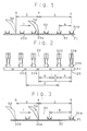
- Spacing A and Spacing B represents distance between adjacent terminals, in two strip terminals of (20) and (30) their relationship are expressed as follows: A ⁇ B [1] A ⁇ B ⁇ 2A [2]
- the carrying apertures (22), (32) shall be located, on their terminal carrier portions (21)and (31) respectively, at point F which is commonly apart as distance C measured from position E where crimping operation is carried out.
- the moving stroke of the feed blade D is determined within a range of the following equation: B ⁇ D ⁇ 2A [3]
- Strip terminal (20) has a plurality of crimp terminals (23) [(23a), (23b) and others] aligned side by side with spacing A and with a terminal carrier (21) having carring apertures (22) [(22a), (22b) and others] positioned in a distance A which is taken from the longitudinal axis (25) of the crimp terminals (23) (Fig.2).
- the longitudinal axis (25) of the crimp terminal (23a) is in a matching position E with that of crimp die (1) (Fig.7).
- the front edges (right side edges) of the carrying aperture (22a) and (22b) are located in a positions which are shown in Fig.1 and Fig.2, where the distance from crimping position E to the front edge F (right side edge) of the carrying aperture (22a) is C and the carrying aperture (22b), where the feed blade is to be mated in order to carry the terminal (23b) to the crimp position E, is located in a position which is also apart length C from the longitudinal axis (25) of terminal (23a).
- FIG.3 and Fig.4 Another strip terminal (31) having similar configuration, but with different locational relationship is illustrated in Fig.3 and Fig.4, where spacing between adjacent crimp terminals (33) is B which is larger than A in the preceeding example and is less than 2A.
- spacing between adjacent crimp terminals (33) is B which is larger than A in the preceeding example and is less than 2A.
- the distance between the front edge (right side edge of carrying aperture (32) and longitudinal axis of adjasent preceeding crimp terminal (33) is B′
- carrying aperture (32a) is biased distance C from the crimp position E
- stroke D of the feed blade (5) is equal to the spacing between adjacent carrying apertures (32a), (32b).
- the feed blade has mated with next aperture when it returns to position G by means of spring (7) and then movement toward I direction is started at once.
- the strip terminal (20) shown in Fig.2 has standardized spacing A between adjacent crimp terminal such as (23a) (23b) and carrying aperture (22) located on terminal carrier (21) in the position with biased distance A′ from the longitudinal axis of crimp terminal (23).
- the second example describes strip terminal (30) shown in Fig.4 where spacing between (33a)(33b) is B and carrying aperture (32) is in a position with biased distance B′ from the longitudinal axis of crimp terminal (33).
Landscapes
- Engineering & Computer Science (AREA)
- Manufacturing & Machinery (AREA)
- Manufacturing Of Electrical Connectors (AREA)
Applications Claiming Priority (2)
| Application Number | Priority Date | Filing Date | Title |
|---|---|---|---|
| JP1988118209U JPH088554Y2 (ja) | 1988-09-08 | 1988-09-08 | 横連鎖端子 |
| JP118209/88U | 1988-09-08 |
Publications (3)
| Publication Number | Publication Date |
|---|---|
| EP0358218A2 true EP0358218A2 (de) | 1990-03-14 |
| EP0358218A3 EP0358218A3 (de) | 1991-07-03 |
| EP0358218B1 EP0358218B1 (de) | 1996-01-31 |
Family
ID=14730907
Family Applications (1)
| Application Number | Title | Priority Date | Filing Date |
|---|---|---|---|
| EP89116571A Expired - Lifetime EP0358218B1 (de) | 1988-09-08 | 1989-09-07 | Krimpendstück |
Country Status (6)
| Country | Link |
|---|---|
| EP (1) | EP0358218B1 (de) |
| JP (1) | JPH088554Y2 (de) |
| KR (1) | KR930000502Y1 (de) |
| CN (1) | CN2054213U (de) |
| DE (1) | DE68925550T2 (de) |
| MY (1) | MY104198A (de) |
Family Cites Families (3)
| Publication number | Priority date | Publication date | Assignee | Title |
|---|---|---|---|---|
| US3420087A (en) * | 1963-02-18 | 1969-01-07 | Amp Inc | Electrical connector means and method of manufacture |
| US3969806A (en) * | 1973-02-20 | 1976-07-20 | Bunker Ramo Corporation | Apparatus and method for crimping terminals |
| JPS5786273U (de) * | 1980-11-14 | 1982-05-27 |
-
1988
- 1988-09-08 JP JP1988118209U patent/JPH088554Y2/ja not_active Expired - Lifetime
-
1989
- 1989-09-04 CN CN89217124U patent/CN2054213U/zh not_active Withdrawn
- 1989-09-06 MY MYPI89001217A patent/MY104198A/en unknown
- 1989-09-07 DE DE68925550T patent/DE68925550T2/de not_active Expired - Fee Related
- 1989-09-07 KR KR2019890013194U patent/KR930000502Y1/ko not_active Expired - Lifetime
- 1989-09-07 EP EP89116571A patent/EP0358218B1/de not_active Expired - Lifetime
Also Published As
| Publication number | Publication date |
|---|---|
| EP0358218A3 (de) | 1991-07-03 |
| EP0358218B1 (de) | 1996-01-31 |
| MY104198A (en) | 1994-02-28 |
| DE68925550D1 (de) | 1996-03-14 |
| DE68925550T2 (de) | 1996-06-05 |
| CN2054213U (zh) | 1990-03-07 |
| JPH0239489U (de) | 1990-03-16 |
| JPH088554Y2 (ja) | 1996-03-06 |
| KR930000502Y1 (ko) | 1993-02-05 |
Similar Documents
| Publication | Publication Date | Title |
|---|---|---|
| US4043017A (en) | Apparatus for inserting wires into terminals and for manufacturing electrical harnesses | |
| US4646404A (en) | Apparatus for manufacturing electrical harnesses | |
| US4729152A (en) | Apparatus and method for assembling electrical harnesses | |
| EP0706242B1 (de) | Verfahren und vorrichtung zum herstellen eines crimp-verbinders | |
| US4742746A (en) | Reworking and sizing of flat conductor cable | |
| US4148130A (en) | Cable harness assembly apparatus | |
| GB2033790A (en) | Apparatus and method for production of wire leads | |
| US4419817A (en) | Electrical harness fabrication apparatus | |
| US4409734A (en) | Harness making apparatus and method | |
| EP0311149B1 (de) | Maschine für die Herstellung eines elektrischen Kabelbaumes | |
| US4638549A (en) | Apparatus for manufacturing electrical harnesses | |
| US3816897A (en) | Apparatus for connecting conductors to terminals in a pre-load electrical connector | |
| GB1325249A (en) | Automatic terminal applicator for insulated nonmetallic ignition type wires | |
| EP0281244B1 (de) | Kabelführungsapparat mit Abstandsregelung für das Herstellen von elektrischen Bündeln | |
| EP0145416B1 (de) | Apparat zur Herstellung von elektrischen Drahtbäumen | |
| US3239924A (en) | Electrical terminal applicator | |
| US5933932A (en) | Apparatus for making electrical harness | |
| US3443299A (en) | Apparatus for trimming and connecting wires | |
| US3986256A (en) | Adapter for positioning multi-conductor cable and electrical connector | |
| US3555672A (en) | High speed semiautomatic termination of coaxial cable | |
| EP0358218B1 (de) | Krimpendstück | |
| EP0168141B1 (de) | Gerät und Verfahren zum Zusammenfassen von mit Kontakten versehenen Drähten zur Herstellung von Kabelbäumen | |
| US4651413A (en) | Wire jig intended for use in a harness-making machine or the like | |
| US4032211A (en) | Multi-conductor half-tap connection | |
| EP0332627B1 (de) | Vorrichtung für die herstellung von leitern oder kabelbäumen |
Legal Events
| Date | Code | Title | Description |
|---|---|---|---|
| PUAI | Public reference made under article 153(3) epc to a published international application that has entered the european phase |
Free format text: ORIGINAL CODE: 0009012 |
|
| AK | Designated contracting states |
Kind code of ref document: A2 Designated state(s): CH DE FR GB IT LI |
|
| PUAL | Search report despatched |
Free format text: ORIGINAL CODE: 0009013 |
|
| AK | Designated contracting states |
Kind code of ref document: A3 Designated state(s): CH DE FR GB IT LI |
|
| 17P | Request for examination filed |
Effective date: 19911217 |
|
| 17Q | First examination report despatched |
Effective date: 19921222 |
|
| GRAA | (expected) grant |
Free format text: ORIGINAL CODE: 0009210 |
|
| AK | Designated contracting states |
Kind code of ref document: B1 Designated state(s): CH DE FR GB IT LI |
|
| ITF | It: translation for a ep patent filed | ||
| REF | Corresponds to: |
Ref document number: 68925550 Country of ref document: DE Date of ref document: 19960314 |
|
| REG | Reference to a national code |
Ref country code: CH Ref legal event code: NV Representative=s name: ISLER & PEDRAZZINI AG PATENTANWAELTE |
|
| ET | Fr: translation filed | ||
| PLBE | No opposition filed within time limit |
Free format text: ORIGINAL CODE: 0009261 |
|
| STAA | Information on the status of an ep patent application or granted ep patent |
Free format text: STATUS: NO OPPOSITION FILED WITHIN TIME LIMIT |
|
| 26N | No opposition filed | ||
| PGFP | Annual fee paid to national office [announced via postgrant information from national office to epo] |
Ref country code: CH Payment date: 20010914 Year of fee payment: 13 |
|
| REG | Reference to a national code |
Ref country code: GB Ref legal event code: IF02 |
|
| PGFP | Annual fee paid to national office [announced via postgrant information from national office to epo] |
Ref country code: GB Payment date: 20020904 Year of fee payment: 14 |
|
| PGFP | Annual fee paid to national office [announced via postgrant information from national office to epo] |
Ref country code: FR Payment date: 20020910 Year of fee payment: 14 |
|
| PGFP | Annual fee paid to national office [announced via postgrant information from national office to epo] |
Ref country code: DE Payment date: 20020911 Year of fee payment: 14 |
|
| PG25 | Lapsed in a contracting state [announced via postgrant information from national office to epo] |
Ref country code: LI Free format text: LAPSE BECAUSE OF NON-PAYMENT OF DUE FEES Effective date: 20020930 Ref country code: CH Free format text: LAPSE BECAUSE OF NON-PAYMENT OF DUE FEES Effective date: 20020930 |
|
| REG | Reference to a national code |
Ref country code: CH Ref legal event code: PL |
|
| PG25 | Lapsed in a contracting state [announced via postgrant information from national office to epo] |
Ref country code: GB Free format text: LAPSE BECAUSE OF NON-PAYMENT OF DUE FEES Effective date: 20030907 |
|
| PG25 | Lapsed in a contracting state [announced via postgrant information from national office to epo] |
Ref country code: DE Free format text: LAPSE BECAUSE OF NON-PAYMENT OF DUE FEES Effective date: 20040401 |
|
| GBPC | Gb: european patent ceased through non-payment of renewal fee |
Effective date: 20030907 |
|
| PG25 | Lapsed in a contracting state [announced via postgrant information from national office to epo] |
Ref country code: FR Free format text: LAPSE BECAUSE OF NON-PAYMENT OF DUE FEES Effective date: 20040528 |
|
| REG | Reference to a national code |
Ref country code: FR Ref legal event code: ST |
|
| PG25 | Lapsed in a contracting state [announced via postgrant information from national office to epo] |
Ref country code: IT Free format text: LAPSE BECAUSE OF NON-PAYMENT OF DUE FEES;WARNING: LAPSES OF ITALIAN PATENTS WITH EFFECTIVE DATE BEFORE 2007 MAY HAVE OCCURRED AT ANY TIME BEFORE 2007. THE CORRECT EFFECTIVE DATE MAY BE DIFFERENT FROM THE ONE RECORDED. Effective date: 20050907 |