EP0358327B1 - Pneumatique radial - Google Patents
Pneumatique radial Download PDFInfo
- Publication number
- EP0358327B1 EP0358327B1 EP89307865A EP89307865A EP0358327B1 EP 0358327 B1 EP0358327 B1 EP 0358327B1 EP 89307865 A EP89307865 A EP 89307865A EP 89307865 A EP89307865 A EP 89307865A EP 0358327 B1 EP0358327 B1 EP 0358327B1
- Authority
- EP
- European Patent Office
- Prior art keywords
- tread
- tyre
- grooves
- groove
- buttress portion
- Prior art date
- Legal status (The legal status is an assumption and is not a legal conclusion. Google has not performed a legal analysis and makes no representation as to the accuracy of the status listed.)
- Expired - Lifetime
Links
- 101150027068 DEGS1 gene Proteins 0.000 description 6
- 229910000831 Steel Inorganic materials 0.000 description 2
- 239000011324 bead Substances 0.000 description 2
- 238000013016 damping Methods 0.000 description 2
- 230000002542 deteriorative effect Effects 0.000 description 2
- 230000000694 effects Effects 0.000 description 2
- 230000005855 radiation Effects 0.000 description 2
- 230000002787 reinforcement Effects 0.000 description 2
- 239000010959 steel Substances 0.000 description 2
- AFCARXCZXQIEQB-UHFFFAOYSA-N N-[3-oxo-3-(2,4,6,7-tetrahydrotriazolo[4,5-c]pyridin-5-yl)propyl]-2-[[3-(trifluoromethoxy)phenyl]methylamino]pyrimidine-5-carboxamide Chemical compound O=C(CCNC(=O)C=1C=NC(=NC=1)NCC1=CC(=CC=C1)OC(F)(F)F)N1CC2=C(CC1)NN=N2 AFCARXCZXQIEQB-UHFFFAOYSA-N 0.000 description 1
- 230000003247 decreasing effect Effects 0.000 description 1
- 239000004744 fabric Substances 0.000 description 1
- 230000001939 inductive effect Effects 0.000 description 1
- 230000035939 shock Effects 0.000 description 1
- 238000004804 winding Methods 0.000 description 1
Images




Classifications
-
- B—PERFORMING OPERATIONS; TRANSPORTING
- B60—VEHICLES IN GENERAL
- B60C—VEHICLE TYRES; TYRE INFLATION; TYRE CHANGING; CONNECTING VALVES TO INFLATABLE ELASTIC BODIES IN GENERAL; DEVICES OR ARRANGEMENTS RELATED TO TYRES
- B60C11/00—Tyre tread bands; Tread patterns; Anti-skid inserts
- B60C11/01—Shape of the shoulders between tread and sidewall, e.g. rounded, stepped or cantilevered
Definitions
- the present invention relates to a radial tyre.
- the rigidity of the tread portion is higher in the shoulder regions due to the hoop effect of the belt reinforcement and also the thicker tread rubber. Accordingly, the shoulder regions largely effect the occurrence of vehicle wander when running on a road having a surface which is partially inclined to the side.
- a tyre according to the preamble of claim 1 is known, e.g. from US-A-4 724 878.
- a radial tyre comprising a tread portion provided with wide main grooves and narrow grooves extending circumferentially of the tyre, said narrow grooves having axially outer groove sidewalls and being disposed in a boundary region between said tread portion and an adjacent buttress portion, said narrow grooves being inclined axially inwards at the bottom by an angle ⁇ , and the tread surface and the surface of the adjacent buttress portion crossing each other to form an intersection point, characterised in that said angle ⁇ is in the range of 0 to 5 degrees to the normal direction of the tread surface and the radially outer edge of the axially outer groove sidewall of the narrow groove is positioned at the intersection point.
- a radial tyre 1 has a tread portion 2 and a pair of sidewalls 6 extending to beads (not shown).
- a radial ply carcass 7 extends between the bead portions through the sidewalls 6 and the tread portion 2.
- the tread 2 is reinforced by a breaker comprising at least one belt layer 9 between the carcass 7 and the tread 2 composed of layers of steel cord fabric or the like.
- the tread portion 2 is provided with tread grooves 4 to form an all-season type tread pattern which changes from a block pattern to a rib pattern as tread wear progresses.
- the tread grooves 4 include five longitudinal main grooves G, G1, G2 extending in a zigzag fashion in the circumferential direction of the tyre, lateral grooves L laid across the longitudinal grooves G, and shoulder lateral grooves 11.
- the shoulder lateral grooves 11 extend axially across the shoulder ribs 10 which are formed axially outside the outermost longitudinal grooves G1 and G2 to divide them each into a row of shoulder blocks.
- the groove depths of the main grooves, G, G1 and G2 are identical to each other, and are deeper than the lateral grooves L and 11, so that the tread pattern changes from a block pattern to a rib pattern as tread wear progresses.
- the tread portion 2 is connected to the sidewalls 6 by buttress portions 3.
- the buttress portions 3 are provided with radiation grooves 12 extending axially of the tyre and connected to the shoulder lateral grooves 11. Furthermore, each buttress 3 is provided with a circumferentially extending wide, shallow groove 13 in which in narrow, shallow groove 15 is formed as a continuous groove having a winding path in the circumferential direction of the tyre, to increase heat radiation from the buttress region 3.
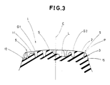
- a circumferentially extending narrow groove 5 is formed at a position near the intersection P between the surface of the tread portion 2 and the surface of the buttress portion 3, in other words, the edge of the ground contacting area of the tread.
- the radially outer edge of the axially outer groove sidewall 5A is positioned at and along the above mentioned intersection P, as shown in Figure 4.
- centre line 1 of the narrow groove 5 is inclined axially inwardly at the bottom of the groove by an angle (beta) which is between 0 to 5 degrees with respect to the normal line n drawn perpendicular to the tread surface S from the above-mentioned position near to the intersection P in order to prevent tear failure.
- the groove width of the narrow groove 5 is set to be less than 5mm and more preferably about 2mm.
- the ratio D1/D of the groove depth D1 from the tread surface S to the groove bottom, to the groove depth D of the longitudinal main grooves is set to be 0.8 to 1.1.
- the rigidity of the tread rubber is reduced in the shoulder regions B, thereby effectively suppressing the occurrence of vehicle wander.
- narrow groove 5 extends circumferentially of the tyre, it does not produce the so-called heel and toe wear.
- the tangent X to the buttress portion 3 at the intersection P is inclined at an angle (alpha) between 25 and 35 degrees with respect to the tangent Y to the tread portion 2 at the same intersection O.
- contour of the buttress portion adjacent to the intersection P is formed in a circular arc having a radius R1 of 15 to 35mm.
- a part of the buttress portion 3 adjacent to the intersection P, that is the tyre should B is formed in a curved form having a specified radius and inclination angle, which makes it able to easily ride over a step difference A on a road.
- test tyres were mounted on the front wheels of a 2-D type truck, and then, running at a speed of 80km/h under the specified load, the wandering phenomenon and the stability were evaluated on a scale of 100 by driver feeling. The larger the index, the better the performance.
- test tyres inflated to 7.0kg/sq.cm, were mounted on a 4-ton truck. Then, the wandering phenomenon and the stability were evaluated on a 100 point scale by the test driver's feeling, running at speed 100 km/h under the specified load.
- the stability was evaluated from stability in straight running, steering response whether heavy or not and quick or slow, smoothness when changing a lane, damping and road grip and so on.
- a radial tyre provided with a narrow groove near the tread edge has the rigidity of the tyre shoulder lowered, whereby vehicle wandering is effectively suppressed to improve running stability, and shock when riding over a rut was alleviated to improve the ride.
Landscapes
- Engineering & Computer Science (AREA)
- Mechanical Engineering (AREA)
- Tires In General (AREA)
Claims (4)
- Pneumatique à carcasse radiale, comprenant une partie (2) de bande de roulement ayant des gorges principales larges (G, G1, G2) et des gorges étroites (5) disposées suivant la circonférence du pneumatique, les gorges étroites (5) ayant des parois latérales axialement externes (5A) et étant placées dans une région limite entre la partie (2) de bande de roulement et une partie adjacente de renfort (3), les gorges étroites étant inclinées axialement vers l'intérieur au fond d'un angle (β) et la surface (S) de la bande de roulement et la surface de la partie adjacente de renfort (3) se recoupant pour la formation d'un point d'intersection (P), caractérisé en ce que l'angle (β) est compris entre 0 et 5° par rapport à la direction normale (n) à la surface (S) de la bande de roulement, et le bord radialement externe de la paroi latérale axialement externe (5A) de la gorge étroite (5) est placé au point d'intersection (P).
- Pneumatique selon la revendication 1, caractérisé en ce que la partie (3) de renfort est formée de manière que la tangente X à la surface de la partie de renfort (3) au point d'intersection (P) entre la partie (2) de bande de roulement et la partie (3) de renfort est inclinée d'un angle (α) de 25 à 35° par rapport à la tangente Y à la surface (S) de la bande de roulement au point d'intersection (P).
- Pneumatique selon la revendication 1 ou 2, caractérisé en ce que le profil de la partie de renfort (3) a une partie en arc de cercle de rayon R1 compris entre 15 et 35 mm, adjacente au point d'intersection (P) de la partie (2) de bande de roulement et de la partie de renfort (3).
- Pneumatique selon la revendication 1, 2 ou 3, caractérisé en ce que le rapport D1/D de la profondeur D1 des gorges étroites (5) à la profondeur D des gorges principales (G, G1, G2) est compris entre 0,8 et 1,1.
Applications Claiming Priority (2)
| Application Number | Priority Date | Filing Date | Title |
|---|---|---|---|
| JP63202558A JPH0253606A (ja) | 1988-08-11 | 1988-08-11 | ラジアルタイヤ |
| JP202558/88 | 1988-08-11 |
Publications (2)
| Publication Number | Publication Date |
|---|---|
| EP0358327A1 EP0358327A1 (fr) | 1990-03-14 |
| EP0358327B1 true EP0358327B1 (fr) | 1993-05-26 |
Family
ID=16459487
Family Applications (1)
| Application Number | Title | Priority Date | Filing Date |
|---|---|---|---|
| EP89307865A Expired - Lifetime EP0358327B1 (fr) | 1988-08-11 | 1989-08-02 | Pneumatique radial |
Country Status (4)
| Country | Link |
|---|---|
| US (1) | US5010936A (fr) |
| EP (1) | EP0358327B1 (fr) |
| JP (1) | JPH0253606A (fr) |
| DE (1) | DE68906736T2 (fr) |
Families Citing this family (17)
| Publication number | Priority date | Publication date | Assignee | Title |
|---|---|---|---|---|
| JPH02179507A (ja) * | 1988-12-29 | 1990-07-12 | Bridgestone Corp | 空気入りタイヤ |
| JP2544532B2 (ja) * | 1990-06-15 | 1996-10-16 | 住友ゴム工業株式会社 | 重荷重用タイヤ |
| FR2669273A1 (fr) * | 1990-11-15 | 1992-05-22 | Michelin & Cie | Bande de roulement d'enveloppe de pneumatique pour vehicules poids-lourds. |
| US5360043A (en) * | 1991-07-26 | 1994-11-01 | The Goodyear Tire & Rubber Company | Asymmetric tread for a tire |
| JP3344794B2 (ja) * | 1993-12-15 | 2002-11-18 | 横浜ゴム株式会社 | 空気入りラジアルタイヤ |
| US6109316A (en) * | 1998-01-26 | 2000-08-29 | Michelin Recherche Et Technique S.A. | Tire having improved tread portion for reducing formation of anomalies causing user dissatisfaction |
| JP3076553B2 (ja) * | 1998-12-21 | 2000-08-14 | 住友ゴム工業株式会社 | 重荷重用タイヤ |
| US20040055683A1 (en) * | 2002-09-19 | 2004-03-25 | Feider Georges Gaston | Truck steer tire, a mold and a method of molding |
| JP4839885B2 (ja) * | 2006-02-24 | 2011-12-21 | 横浜ゴム株式会社 | 空気入りタイヤ |
| JP4338743B2 (ja) | 2007-03-15 | 2009-10-07 | 住友ゴム工業株式会社 | 空気入りタイヤ |
| WO2010021288A1 (fr) * | 2008-08-22 | 2010-02-25 | 株式会社ブリヂストン | Pneu |
| JP5331462B2 (ja) * | 2008-11-27 | 2013-10-30 | 株式会社ブリヂストン | タイヤ |
| JP5606847B2 (ja) * | 2010-09-16 | 2014-10-15 | 東洋ゴム工業株式会社 | 空気入りタイヤ |
| DE202013003767U1 (de) * | 2013-04-20 | 2013-05-15 | GM Global Technology Operations LLC (n. d. Ges. d. Staates Delaware) | Kraftfahrzeug mit Fahrbahnbeurteilungseinrichtung |
| JP2014213835A (ja) * | 2013-04-30 | 2014-11-17 | 株式会社ブリヂストン | 空気入りタイヤ |
| AU2015201350B2 (en) * | 2014-03-25 | 2018-05-10 | Sumitomo Rubber Industries Ltd. | Pneumatic tyre |
| WO2021222787A1 (fr) * | 2020-04-30 | 2021-11-04 | Compagnie Generale Des Etablissements Michelin | Pneu non pneumatique |
Family Cites Families (9)
| Publication number | Priority date | Publication date | Assignee | Title |
|---|---|---|---|---|
| GB1192731A (en) * | 1966-08-26 | 1970-05-20 | Dunlop Co Ltd | Improvements in or relating to Tyres |
| FR1568310A (fr) * | 1968-03-28 | 1969-05-23 | ||
| JPS53133802A (en) * | 1977-04-26 | 1978-11-22 | Bridgestone Corp | Wear resistant radial pneumatic type for heavy load |
| JPS5555005A (en) * | 1978-10-17 | 1980-04-22 | Bridgestone Corp | Radial tire for heavy vehicle restrained in wandering phenomenon |
| US4480671A (en) * | 1982-04-26 | 1984-11-06 | Michelin Recherche Et Technique S.A. | Tread and heavy duty tire |
| JPS62265006A (ja) * | 1986-05-14 | 1987-11-17 | Bridgestone Corp | 空気入りタイヤ |
| JPS6332002U (fr) * | 1986-08-19 | 1988-03-01 | ||
| JP2860543B2 (ja) * | 1987-01-26 | 1999-02-24 | 横浜ゴム株式会社 | 重荷重用空気入りラジアルタイヤ |
| JP2617713B2 (ja) * | 1987-03-26 | 1997-06-04 | 横浜ゴム株式会社 | 重荷重用空気入りラジアルタイヤ |
-
1988
- 1988-08-11 JP JP63202558A patent/JPH0253606A/ja active Pending
-
1989
- 1989-07-26 US US07/385,148 patent/US5010936A/en not_active Expired - Fee Related
- 1989-08-02 DE DE8989307865T patent/DE68906736T2/de not_active Expired - Fee Related
- 1989-08-02 EP EP89307865A patent/EP0358327B1/fr not_active Expired - Lifetime
Also Published As
| Publication number | Publication date |
|---|---|
| DE68906736D1 (de) | 1993-07-01 |
| EP0358327A1 (fr) | 1990-03-14 |
| US5010936A (en) | 1991-04-30 |
| JPH0253606A (ja) | 1990-02-22 |
| DE68906736T2 (de) | 1993-09-09 |
Similar Documents
| Publication | Publication Date | Title |
|---|---|---|
| EP1007377B1 (fr) | Nervure sacrificielle pour longevite de pneumatique amelioree | |
| EP0358327A1 (fr) | Pneumatique radial | |
| EP0285695B1 (fr) | Bandage pneumatique radial pour poids lourds | |
| EP1473176B1 (fr) | Pneumatique pour motocyclette | |
| EP2960079B1 (fr) | Pneu | |
| EP1120295B1 (fr) | Bandage pneumatique | |
| US4480671A (en) | Tread and heavy duty tire | |
| US5360044A (en) | Pneumatic radial tire with high cornering and steering stability | |
| EP1288023B1 (fr) | Bandage pneumatique tout-terrain | |
| EP0688685B1 (fr) | Bandage pneumatique | |
| EP0256794B1 (fr) | Bandage pneumatique radial | |
| EP0547040A2 (fr) | Bandage pneumatique radial | |
| EP0312300B1 (fr) | Bandage pneumatique radial | |
| US6192953B1 (en) | Heavy duty radial tire having tapered shoulder portions | |
| JP2544532B2 (ja) | 重荷重用タイヤ | |
| GB2178380A (en) | Pneumatic tire | |
| EP0309134B1 (fr) | Bandage pneumatique radial pour poids lourds | |
| EP0295898B1 (fr) | Pneumatique à carcasse radiale pour automobiles | |
| EP0426068B1 (fr) | Méthode de montage de bandages pneumatiques | |
| US5318085A (en) | Radial tire having reduced treadwear | |
| US4589461A (en) | Pneumatic belted tires | |
| EP0321730B1 (fr) | Pneumatique radial à profil bas | |
| EP0486274B1 (fr) | Pneumatique radial | |
| JPH08188015A (ja) | 車両用前後輪空気入りタイヤ対 | |
| EP0508813B1 (fr) | Bandage pneumatique tout-terrain |
Legal Events
| Date | Code | Title | Description |
|---|---|---|---|
| PUAI | Public reference made under article 153(3) epc to a published international application that has entered the european phase |
Free format text: ORIGINAL CODE: 0009012 |
|
| AK | Designated contracting states |
Kind code of ref document: A1 Designated state(s): DE FR GB |
|
| 17P | Request for examination filed |
Effective date: 19900911 |
|
| 17Q | First examination report despatched |
Effective date: 19920327 |
|
| GRAA | (expected) grant |
Free format text: ORIGINAL CODE: 0009210 |
|
| AK | Designated contracting states |
Kind code of ref document: B1 Designated state(s): DE FR GB |
|
| REF | Corresponds to: |
Ref document number: 68906736 Country of ref document: DE Date of ref document: 19930701 |
|
| ET | Fr: translation filed | ||
| PLBE | No opposition filed within time limit |
Free format text: ORIGINAL CODE: 0009261 |
|
| STAA | Information on the status of an ep patent application or granted ep patent |
Free format text: STATUS: NO OPPOSITION FILED WITHIN TIME LIMIT |
|
| 26N | No opposition filed | ||
| PGFP | Annual fee paid to national office [announced via postgrant information from national office to epo] |
Ref country code: DE Payment date: 20000729 Year of fee payment: 12 |
|
| PGFP | Annual fee paid to national office [announced via postgrant information from national office to epo] |
Ref country code: GB Payment date: 20000802 Year of fee payment: 12 |
|
| PGFP | Annual fee paid to national office [announced via postgrant information from national office to epo] |
Ref country code: FR Payment date: 20000811 Year of fee payment: 12 |
|
| PG25 | Lapsed in a contracting state [announced via postgrant information from national office to epo] |
Ref country code: GB Free format text: LAPSE BECAUSE OF NON-PAYMENT OF DUE FEES Effective date: 20010802 |
|
| GBPC | Gb: european patent ceased through non-payment of renewal fee |
Effective date: 20010802 |
|
| PG25 | Lapsed in a contracting state [announced via postgrant information from national office to epo] |
Ref country code: FR Free format text: LAPSE BECAUSE OF NON-PAYMENT OF DUE FEES Effective date: 20020430 |
|
| PG25 | Lapsed in a contracting state [announced via postgrant information from national office to epo] |
Ref country code: DE Free format text: LAPSE BECAUSE OF NON-PAYMENT OF DUE FEES Effective date: 20020501 |
|
| REG | Reference to a national code |
Ref country code: FR Ref legal event code: ST |