EP1120295B1 - Bandage pneumatique - Google Patents
Bandage pneumatique Download PDFInfo
- Publication number
- EP1120295B1 EP1120295B1 EP01300592A EP01300592A EP1120295B1 EP 1120295 B1 EP1120295 B1 EP 1120295B1 EP 01300592 A EP01300592 A EP 01300592A EP 01300592 A EP01300592 A EP 01300592A EP 1120295 B1 EP1120295 B1 EP 1120295B1
- Authority
- EP
- European Patent Office
- Prior art keywords
- axially
- grooves
- oblique
- pneumatic tyre
- tyre according
- Prior art date
- Legal status (The legal status is an assumption and is not a legal conclusion. Google has not performed a legal analysis and makes no representation as to the accuracy of the status listed.)
- Expired - Lifetime
Links
- 230000002457 bidirectional effect Effects 0.000 claims 1
- 238000012360 testing method Methods 0.000 description 17
- 239000010426 asphalt Substances 0.000 description 4
- 230000007423 decrease Effects 0.000 description 3
- 230000003247 decreasing effect Effects 0.000 description 3
- XLYOFNOQVPJJNP-UHFFFAOYSA-N water Substances O XLYOFNOQVPJJNP-UHFFFAOYSA-N 0.000 description 2
- 229910000831 Steel Inorganic materials 0.000 description 1
- 230000001133 acceleration Effects 0.000 description 1
- 239000012141 concentrate Substances 0.000 description 1
- 238000013016 damping Methods 0.000 description 1
- 230000006866 deterioration Effects 0.000 description 1
- 230000000694 effects Effects 0.000 description 1
- 238000000034 method Methods 0.000 description 1
- 238000011056 performance test Methods 0.000 description 1
- 230000010363 phase shift Effects 0.000 description 1
- 229920000728 polyester Polymers 0.000 description 1
- 230000003014 reinforcing effect Effects 0.000 description 1
- 238000013112 stability test Methods 0.000 description 1
- 239000010959 steel Substances 0.000 description 1
- 239000004575 stone Substances 0.000 description 1
Images


Classifications
-
- B—PERFORMING OPERATIONS; TRANSPORTING
- B60—VEHICLES IN GENERAL
- B60C—VEHICLE TYRES; TYRE INFLATION; TYRE CHANGING; CONNECTING VALVES TO INFLATABLE ELASTIC BODIES IN GENERAL; DEVICES OR ARRANGEMENTS RELATED TO TYRES
- B60C11/00—Tyre tread bands; Tread patterns; Anti-skid inserts
- B60C11/01—Shape of the shoulders between tread and sidewall, e.g. rounded, stepped or cantilevered
-
- B—PERFORMING OPERATIONS; TRANSPORTING
- B60—VEHICLES IN GENERAL
- B60C—VEHICLE TYRES; TYRE INFLATION; TYRE CHANGING; CONNECTING VALVES TO INFLATABLE ELASTIC BODIES IN GENERAL; DEVICES OR ARRANGEMENTS RELATED TO TYRES
- B60C11/00—Tyre tread bands; Tread patterns; Anti-skid inserts
- B60C11/03—Tread patterns
- B60C11/13—Tread patterns characterised by the groove cross-section, e.g. for buttressing or preventing stone-trapping
- B60C11/1376—Three dimensional block surfaces departing from the enveloping tread contour
- B60C11/1384—Three dimensional block surfaces departing from the enveloping tread contour with chamfered block corners
-
- B—PERFORMING OPERATIONS; TRANSPORTING
- B60—VEHICLES IN GENERAL
- B60C—VEHICLE TYRES; TYRE INFLATION; TYRE CHANGING; CONNECTING VALVES TO INFLATABLE ELASTIC BODIES IN GENERAL; DEVICES OR ARRANGEMENTS RELATED TO TYRES
- B60C11/00—Tyre tread bands; Tread patterns; Anti-skid inserts
- B60C11/03—Tread patterns
- B60C11/0302—Tread patterns directional pattern, i.e. with main rolling direction
-
- B—PERFORMING OPERATIONS; TRANSPORTING
- B60—VEHICLES IN GENERAL
- B60C—VEHICLE TYRES; TYRE INFLATION; TYRE CHANGING; CONNECTING VALVES TO INFLATABLE ELASTIC BODIES IN GENERAL; DEVICES OR ARRANGEMENTS RELATED TO TYRES
- B60C11/00—Tyre tread bands; Tread patterns; Anti-skid inserts
- B60C11/03—Tread patterns
- B60C11/11—Tread patterns in which the raised area of the pattern consists only of isolated elements, e.g. blocks
-
- B—PERFORMING OPERATIONS; TRANSPORTING
- B60—VEHICLES IN GENERAL
- B60C—VEHICLE TYRES; TYRE INFLATION; TYRE CHANGING; CONNECTING VALVES TO INFLATABLE ELASTIC BODIES IN GENERAL; DEVICES OR ARRANGEMENTS RELATED TO TYRES
- B60C11/00—Tyre tread bands; Tread patterns; Anti-skid inserts
- B60C11/03—Tread patterns
- B60C11/12—Tread patterns characterised by the use of narrow slits or incisions, e.g. sipes
-
- B—PERFORMING OPERATIONS; TRANSPORTING
- B60—VEHICLES IN GENERAL
- B60C—VEHICLE TYRES; TYRE INFLATION; TYRE CHANGING; CONNECTING VALVES TO INFLATABLE ELASTIC BODIES IN GENERAL; DEVICES OR ARRANGEMENTS RELATED TO TYRES
- B60C11/00—Tyre tread bands; Tread patterns; Anti-skid inserts
- B60C11/03—Tread patterns
- B60C11/12—Tread patterns characterised by the use of narrow slits or incisions, e.g. sipes
- B60C11/1259—Depth of the sipe
- B60C2011/1268—Depth of the sipe being different from sipe to sipe
-
- Y—GENERAL TAGGING OF NEW TECHNOLOGICAL DEVELOPMENTS; GENERAL TAGGING OF CROSS-SECTIONAL TECHNOLOGIES SPANNING OVER SEVERAL SECTIONS OF THE IPC; TECHNICAL SUBJECTS COVERED BY FORMER USPC CROSS-REFERENCE ART COLLECTIONS [XRACs] AND DIGESTS
- Y10—TECHNICAL SUBJECTS COVERED BY FORMER USPC
- Y10S—TECHNICAL SUBJECTS COVERED BY FORMER USPC CROSS-REFERENCE ART COLLECTIONS [XRACs] AND DIGESTS
- Y10S152/00—Resilient tires and wheels
- Y10S152/03—Slits in threads
-
- Y—GENERAL TAGGING OF NEW TECHNOLOGICAL DEVELOPMENTS; GENERAL TAGGING OF CROSS-SECTIONAL TECHNOLOGIES SPANNING OVER SEVERAL SECTIONS OF THE IPC; TECHNICAL SUBJECTS COVERED BY FORMER USPC CROSS-REFERENCE ART COLLECTIONS [XRACs] AND DIGESTS
- Y10—TECHNICAL SUBJECTS COVERED BY FORMER USPC
- Y10S—TECHNICAL SUBJECTS COVERED BY FORMER USPC CROSS-REFERENCE ART COLLECTIONS [XRACs] AND DIGESTS
- Y10S152/00—Resilient tires and wheels
- Y10S152/903—Non-directional tread pattern having non-circumferential transverse groove following smooth curved path
Definitions
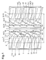
- the pneumatic tyre 1 is a radial tyre of size 215/70R15 for passenger cars.
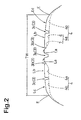
- the tread width TW is the maximum axial width of the ground contacting area under a standard condition in which the tyre is mounted on a standard rim and inflated to a standard load and then loaded with a standard load.
- the standard rim is the "standard rim” specified in JATMA, the “Measuring Rim” in ETRTO, the “Design Rim” in T & RA or the like.
- the standard pressure is the "maximum air pressure" in JATMA, the “Inflation Pressure” in ETRTO, the maximum pressure given in the "Tyre Load Limits at Various Cold Inflation Pressures" table in T & RA or the like.
- each of the oblique grooves 4 is made up of a first oblique groove 4a between the middle circumferential groove 3b and outer circumferential groove 3c, and a second oblique groove 4b between the outer circumferential groove 3c and tread edge E.
- the second oblique grooves 4b comprise grooves whose width gradually increases towards the tread edge E and grooves whose width gradually increases towards the tyre equator, and these two types of grooves are alternately disposed in the tyre circumferential direction.
- the first oblique grooves 4a comprise wide grooves and narrow grooves which are alternately disposed in the tyre circumferential direction, and both the wide and narrow grooves 4a are increased in the width towards the outer circumferential grooves 3c.
- the first oblique groove 4a in this example has a deep part 6 having substantially the same depth as the central circumferential groove 3a, and a shallow part 7 having a depth less than the central circumferential groove 3a.
- the shallow part 7 extends from the inner end 4a1 of the first oblique groove 4a for a length of from 15 to 50 %, preferably 30 to 50 % of the length of the first oblique groove 4a.
- the deep part 6 is defined as the remainder on the axially outside thereof. In the shallow part 7, the depth gradually increases from the inner end 4a1 to the deep part 6.
- the above-mentioned central regions La each form a circumferentially continuous rib 9.
- the middle regions Lb each form a circumferential row of long and narrow blocks 5 of a substantially parallelogram shape.
- the outside regions Lc each forms a circumferential row of blocks 10 of a substantially rectangular shape.
- the sizes of the block pieces 5a, 5b and 5c are gradually increased from the axially inside to the outside such that the areas As1, As2 and As3 of the top surfaces of the block pieces 5a, 5b and 5c, respectively, gradually increase axially outwards, namely, As1 ⁇ As2 ⁇ As3.
- the area As1 of the axially innermost block piece 5a is in a range of from 25 to 80 %, more preferably 30 to 50 % of the widest area As3 of the axially outermost block piece 5c.
- the above-mentioned ribs 9 can be provided with sipes S3 or cuts to adjust the rigidity.
- the arrangement and inclinations of the oblique grooves and sipes are reversed between one side of the tyre equator and the other side.
- the tread pattern is rotational symmetry. Therefore, the tread pattern is bi-directional.
- a unidirectional tread pattern can be formed.
- a variable pitching method can be adopted in arranging the oblique grooves and sipes.
- a phase shift can be provided between one side of the tyre equator and the other side.
Landscapes
- Engineering & Computer Science (AREA)
- Mechanical Engineering (AREA)
- Tires In General (AREA)
Claims (15)
- Bandage pneumatique (1) comprenant une portion (2) de bande de roulement prévue sur chaque côté de l'équateur (C) du bandage pneumatique avec deux rainures circonférentielles droites (3b et 3c) et des rainures obliques (4a) qui s'étendent entre elles pour définir une rangée circonférentielle de blocs étroits et longs circonférentiellement (5) entre elles, lesdites deux rainures circonférentielles droites (3b et 3c) ayant des largeurs différentes, dans lequel la rainure circonférentielle droite interne axialement (3b) a une largeur inférieure à 5 mm et la rainure circonférentielle droite externe axialement (3c) a une largeur non inférieure à 5 mm, lesdites rainures obliques (4a) étant inclinées selon des angles (θ) non supérieurs à 60 degrés par rapport à la direction circonférentielle du bandage pneumatique, lesdites rainures obliques (4a) ayant chacune une largeur variable qui augmente vers les rainures circonférentielles externes axialement (3c), lesdites rainures obliques (4a) ayant chacune une profondeur variable de façon à avoir une partie plus superficielle (7) qui s'étend depuis l'extrémité interne axialement (4a1) de la rainure oblique (4a) sur une longueur représentant 15 à 50 % de la longueur de la rainure oblique (4a),
chacun desdits blocs (5) étant prévu avec au moins deux lamelles (S1, S2) qui s'étendent chacune d'un côté à l'autre du bloc (5) d'une des rainures obliques adjacentes (4a) à l'autre et ayant une inclinaison par rapport à la direction circonférentielle opposée à l'inclinaison des rainures obliques (4a), pour subdiviser le bloc (5) en au moins trois morceaux (5, 5b, 5c) de bloc,
les profondeurs desdites au moins deux lamelles (S1, S2) augmentant progressivement de la lamelle extrême interne axialement (S1) à la lamelle extrême externe axialement (S2). - Bandage pneumatique selon la revendication 1,
caractérisé en ce que
l'angle (θ) de chacune desdites rainures obliques (4a) augmente progressivement de l'extrémité interne axialement (4a1) à l'extrémité externe axialement (4a2), et l'angle minimum au niveau de l'extrémité interne axialement (4a1) étant supérieur à 0 degré mais non supérieur à 30 degrés. - Bandage pneumatique selon la revendication 1 ou 2,
caractérisé en ce que
lesdits au moins trois morceaux (5a, 5b, 5c) de bloc de chacun desdits blocs (5) comporte un morceau (5a) de bloc extrême interne axialement, un morceau (5c) de bloc extrême externe axialement et au moins un morceau (5b) de bloc intermédiaire entre eux, et le morceau (5a) de bloc extrême interne axialement a la plus petite superficie de surface supérieure (AS1). - Bandage pneumatique selon la revendication 3,
caractérisé en ce que
les superficies (AS1, AS2, AS3) de la surface supérieure des morceaux de bloc augmentent progressivement du morceau (5a) de bloc extrême interne axialement au morceau (5c) de bloc extrême externe axialement. - Bandage pneumatique selon la revendication 1, 2 ou 3,
caractérisé en ce que
la portion (2) de bande de roulement est prévue entre les rainures circonférentielles internes axialement (3b) avec une nervure sensiblement droite (9). - Bandage pneumatique selon l'une quelconque des revendications 1 à 5,
caractérisé en ce que
une rainure circonférentielle centrale (3a) est disposée sur l'équateur (C) du bandage pneumatique. - Bandage pneumatique selon la revendication 6,
caractérisé en ce que
la rainure circonférentielle centrale (3a) a une largeur non inférieure à 5 mm. - Bandage pneumatique selon l'une quelconque des revendications 1 à 7,
caractérisé en ce que
chacun desdits blocs (5) a sensiblement une forme de parallélogramme. - Bandage pneumatique selon l'une quelconque des revendications 1 à 8,
caractérisé en ce que
lesdites rainures obliques (4a) comportent des rainures larges et des rainures étroites alternées. - Bandage pneumatique selon la revendication 9,
caractérisé en ce que
lesdites rainures obliques (4a) ont des largeurs non inférieures à 2,5 % de la largeur (TW) de la bande de roulement. - Bandage pneumatique selon l'une quelconque des revendications 1 à 10,
caractérisé en ce que
dans la partie plus superficielle (7) de la rainure oblique (4a), la profondeur augmente progressivement de l'extrémité interne axialement (4a1) à l'extrémité externe axialement (4a2). - Bandage pneumatique selon l'une quelconque des revendications 1 à 11,
caractérisé en ce que
la portion (2) de bande de roulement est prévue avec des secondes rainures obliques (4b) qui s'étendent de la rainure circonférentielle externe axialement (3c) au bord adjacent (E) de la bande de roulement, les secondes rainures obliques (4b) ayant des largeurs différentes y compris une largeur variable croissante axialement vers l'intérieur et une largeur variable croissante axialement vers l'extérieur. - Bandage pneumatique selon la revendication 12,
caractérisé en ce que
sur chaque côté de l'équateur (C) du bandage pneumatique, lesdites rainures obliques (4a) sont inclinées vers une direction circonférentielle par rapport à la direction axiale du bandage pneumatique, mais les secondes rainures obliques (4b) son inclinées vers la direction circonférentielle opposée à celles-ci. - Bandage pneumatique selon l'une quelconque des revendications 1 à 13,
caractérisé en ce que
lesdites rainures obliques (4a) et lamelles (S1, S2) forment un dessin bidirectionnel de bande de roulement. - Bandage pneumatique selon l'une quelconque des revendications 1 à 13,
caractérisé en ce que
lesdites rainures obliques (4a) et lamelles (S1, S2) forment un dessin unidirectionnel de bande de roulement.
Applications Claiming Priority (2)
| Application Number | Priority Date | Filing Date | Title |
|---|---|---|---|
| JP2000014702A JP3367927B2 (ja) | 2000-01-24 | 2000-01-24 | 空気入りタイヤ |
| JP2000014702 | 2000-01-24 |
Publications (3)
| Publication Number | Publication Date |
|---|---|
| EP1120295A2 EP1120295A2 (fr) | 2001-08-01 |
| EP1120295A3 EP1120295A3 (fr) | 2003-02-12 |
| EP1120295B1 true EP1120295B1 (fr) | 2007-03-21 |
Family
ID=18542121
Family Applications (1)
| Application Number | Title | Priority Date | Filing Date |
|---|---|---|---|
| EP01300592A Expired - Lifetime EP1120295B1 (fr) | 2000-01-24 | 2001-01-23 | Bandage pneumatique |
Country Status (6)
| Country | Link |
|---|---|
| US (1) | US6626215B2 (fr) |
| EP (1) | EP1120295B1 (fr) |
| JP (1) | JP3367927B2 (fr) |
| KR (1) | KR100791867B1 (fr) |
| CN (1) | CN100436165C (fr) |
| DE (1) | DE60127327T2 (fr) |
Families Citing this family (49)
| Publication number | Priority date | Publication date | Assignee | Title |
|---|---|---|---|---|
| JP3367927B2 (ja) * | 2000-01-24 | 2003-01-20 | 住友ゴム工業株式会社 | 空気入りタイヤ |
| JP4632593B2 (ja) * | 2001-08-31 | 2011-02-16 | 住友ゴム工業株式会社 | 空気入りタイヤ |
| JP4107385B2 (ja) * | 2002-12-03 | 2008-06-25 | 横浜ゴム株式会社 | 空気入りタイヤ |
| JP4015573B2 (ja) * | 2003-02-28 | 2007-11-28 | 住友ゴム工業株式会社 | 空気入りタイヤ |
| JP4202824B2 (ja) * | 2003-05-28 | 2008-12-24 | 住友ゴム工業株式会社 | 空気入りタイヤ |
| EP1641637B1 (fr) * | 2003-07-04 | 2010-04-21 | Pirelli Tyre S.p.A. | Paire de pneumatiques avant et arriere pour motocyclettes, et procede destine a ameliorer le comportement sur sol mouille et sec d'une motocyclette equipee de ladite paire de pneumatiques |
| KR20050038131A (ko) * | 2003-10-21 | 2005-04-27 | 한국타이어 주식회사 | 사계절용 타이어 트레드 패턴구조 |
| KR20050038130A (ko) * | 2003-10-21 | 2005-04-27 | 한국타이어 주식회사 | 고성능 타이어의 트레드 패턴구조 |
| KR20050039425A (ko) * | 2003-10-25 | 2005-04-29 | 한국타이어 주식회사 | 하이드로 플래닝 성능을 향상시킨 타이어의 트레드 패턴 |
| US9873290B2 (en) | 2004-07-16 | 2018-01-23 | Pirelli Tyre S.P.A. | High-performance tyre for a motor vehicle |
| US8622104B2 (en) | 2004-07-16 | 2014-01-07 | Pirelli Tyre S.P.A. | High-performance type for a motor vehicle |
| JP4545565B2 (ja) * | 2004-11-25 | 2010-09-15 | 東洋ゴム工業株式会社 | 空気入りタイヤ |
| WO2006059560A1 (fr) * | 2004-11-30 | 2006-06-08 | The Yokohama Rubber Co., Ltd. | Bandage pneumatique |
| US7188650B2 (en) * | 2004-12-28 | 2007-03-13 | The Goodyear Tire & Rubber Company | Siped tire tread with high transverse stiffness |
| EP1695844B1 (fr) * | 2005-02-25 | 2011-04-20 | Continental Reifen Deutschland GmbH | Pneumatique pour véhicule muni d'un profil de bande de roulement |
| USD534487S1 (en) | 2005-04-01 | 2007-01-02 | Bridgestone Firestone North American Tire, Llc | Tire tread |
| USD554052S1 (en) | 2006-05-16 | 2007-10-30 | Bridgestone Firestone North American Tire, Llc | Tire tread |
| EP2028025B1 (fr) * | 2006-06-12 | 2011-10-19 | The Yokohama Rubber Co., Ltd. | Pneumatique |
| JP4214159B2 (ja) * | 2006-06-29 | 2009-01-28 | 住友ゴム工業株式会社 | 空気入りタイヤ |
| US7819153B2 (en) * | 2006-11-08 | 2010-10-26 | Bridgestone Americas Tire Operations, Llc | Tire including concave recesses in a circumferential tread |
| WO2008075630A1 (fr) * | 2006-12-20 | 2008-06-26 | Bridgestone Corporation | Pneumatique |
| JP5278127B2 (ja) * | 2008-06-02 | 2013-09-04 | 横浜ゴム株式会社 | 空気入りタイヤ |
| JP4580437B2 (ja) * | 2008-06-17 | 2010-11-10 | 住友ゴム工業株式会社 | 自動二輪車用タイヤ |
| CN101607512B (zh) * | 2008-06-18 | 2012-09-05 | 青岛黄海橡胶股份有限公司 | 轿车子午线轮胎胎面 |
| BRPI0903293B1 (pt) * | 2008-09-11 | 2020-10-13 | The Goodyear Tire & Rubber Company | pneumático tendo uma banda de rodagem de pneu |
| AU2010207199B2 (en) * | 2009-01-26 | 2012-12-13 | Bridgestone Corporation | Tire |
| JP5478284B2 (ja) * | 2010-01-29 | 2014-04-23 | 株式会社ブリヂストン | タイヤ |
| USD642975S1 (en) | 2010-02-16 | 2011-08-09 | Bridgestone Americas Tire Operations, Llc | Tire tread |
| JP5177180B2 (ja) * | 2010-06-18 | 2013-04-03 | 横浜ゴム株式会社 | 空気入りタイヤ |
| JP5185989B2 (ja) | 2010-09-02 | 2013-04-17 | 住友ゴム工業株式会社 | 空気入りタイヤ |
| JP5406911B2 (ja) * | 2011-12-28 | 2014-02-05 | 住友ゴム工業株式会社 | 空気入りタイヤ |
| JP5432981B2 (ja) | 2011-12-29 | 2014-03-05 | 住友ゴム工業株式会社 | 空気入りタイヤ |
| EP2620299B1 (fr) * | 2012-01-26 | 2015-06-17 | Sumitomo Rubber Industries, Ltd. | Pneu |
| JP5629283B2 (ja) | 2012-03-15 | 2014-11-19 | 住友ゴム工業株式会社 | 空気入りタイヤ |
| WO2013191119A1 (fr) | 2012-06-19 | 2013-12-27 | 株式会社ブリヂストン | Pneumatique |
| JP6012442B2 (ja) * | 2012-11-30 | 2016-10-25 | 株式会社ブリヂストン | 空気入りタイヤ |
| CN104822544B (zh) | 2012-11-30 | 2017-10-03 | 株式会社普利司通 | 充气轮胎 |
| KR101419613B1 (ko) * | 2012-12-26 | 2014-07-14 | 한국타이어 주식회사 | 트레드 블록이 개선된 공기입 타이어 |
| JP6002032B2 (ja) * | 2012-12-28 | 2016-10-05 | 株式会社ブリヂストン | タイヤ |
| JP6211310B2 (ja) * | 2013-06-05 | 2017-10-11 | 株式会社ブリヂストン | 空気入りタイヤ |
| JP5780318B2 (ja) * | 2014-01-29 | 2015-09-16 | 横浜ゴム株式会社 | 空気入りタイヤ |
| JP5993403B2 (ja) * | 2014-05-29 | 2016-09-14 | 住友ゴム工業株式会社 | 空気入りタイヤ |
| CN104228472A (zh) * | 2014-10-08 | 2014-12-24 | 安徽佳通乘用子午线轮胎有限公司 | 超高性能全天侯轿车轮胎 |
| FR3030371A1 (fr) * | 2014-12-23 | 2016-06-24 | Michelin & Cie | Bande de roulement pour pneu hivernal poids lourd |
| JP6414245B2 (ja) * | 2017-02-14 | 2018-10-31 | 横浜ゴム株式会社 | 空気入りタイヤ |
| JP6931190B2 (ja) * | 2017-03-24 | 2021-09-01 | 住友ゴム工業株式会社 | タイヤ |
| EP3378678B1 (fr) * | 2017-03-24 | 2021-01-20 | Sumitomo Rubber Industries, Ltd. | Pneumatique |
| JP7298369B2 (ja) * | 2019-07-30 | 2023-06-27 | 住友ゴム工業株式会社 | タイヤ |
| JP7632106B2 (ja) | 2021-06-15 | 2025-02-19 | 住友ゴム工業株式会社 | タイヤ |
Family Cites Families (20)
| Publication number | Priority date | Publication date | Assignee | Title |
|---|---|---|---|---|
| US2926715A (en) * | 1956-11-23 | 1960-03-01 | Us Rubber Co | Tire tread |
| EP0173783B1 (fr) * | 1984-08-28 | 1989-06-14 | The Goodyear Tire & Rubber Company | Bandage pneumatique |
| JPH0241908A (ja) * | 1988-08-02 | 1990-02-13 | Bridgestone Corp | 空気入りタイヤ |
| JP2900267B2 (ja) * | 1989-03-15 | 1999-06-02 | 横浜ゴム株式会社 | 空気入りタイヤ |
| JP2755995B2 (ja) * | 1989-06-07 | 1998-05-25 | 株式会社ブリヂストン | 空気入りタイヤ |
| US5198047A (en) * | 1990-11-14 | 1993-03-30 | The Goodyear Tire & Rubber Company | Winter type tire tread |
| JP3391538B2 (ja) * | 1994-02-02 | 2003-03-31 | 住友ゴム工業株式会社 | スタッドレスタイヤ |
| ES2150531T3 (es) * | 1994-06-23 | 2000-12-01 | Bridgestone Corp | Cubiertas de neumatico. |
| JPH08142608A (ja) * | 1994-11-17 | 1996-06-04 | Bridgestone Corp | 空気入りラジアルタイヤ |
| US5824169A (en) * | 1995-01-20 | 1998-10-20 | The Goodyear Tire & Rubber Company | Pneumatic tire having improved wear properties |
| JPH092027A (ja) * | 1995-06-23 | 1997-01-07 | Bridgestone Corp | 乗用車用空気入りラジアルタイヤ |
| US5837074A (en) * | 1995-12-29 | 1998-11-17 | Sumitomo Rubber Industries, Ltd. | Pneumatic tire |
| JP2934405B2 (ja) * | 1996-01-30 | 1999-08-16 | 住友ゴム工業株式会社 | 空気入りタイヤ |
| JP3718021B2 (ja) * | 1997-02-21 | 2005-11-16 | 株式会社ブリヂストン | オール・シーズン乗用車用空気入りラジアル・タイヤ |
| JPH10264612A (ja) * | 1997-03-24 | 1998-10-06 | Yokohama Rubber Co Ltd:The | 空気入りラジアルタイヤ |
| JP3822310B2 (ja) * | 1997-03-26 | 2006-09-20 | 株式会社ブリヂストン | 空気入りタイヤ |
| DE69930481T2 (de) * | 1998-10-30 | 2006-10-19 | Sumitomo Rubber Industries Ltd., Kobe | Fahrzeugreifen |
| JP4209016B2 (ja) | 1998-11-09 | 2009-01-14 | 株式会社ブリヂストン | 排水性能に優れた乗用車用空気入りタイヤ |
| JP4302218B2 (ja) | 1998-12-21 | 2009-07-22 | 住友ゴム工業株式会社 | 空気入りタイヤ |
| JP3367927B2 (ja) * | 2000-01-24 | 2003-01-20 | 住友ゴム工業株式会社 | 空気入りタイヤ |
-
2000
- 2000-01-24 JP JP2000014702A patent/JP3367927B2/ja not_active Expired - Fee Related
-
2001
- 2001-01-22 KR KR1020010003570A patent/KR100791867B1/ko not_active Expired - Fee Related
- 2001-01-23 EP EP01300592A patent/EP1120295B1/fr not_active Expired - Lifetime
- 2001-01-23 CN CNB01101718XA patent/CN100436165C/zh not_active Expired - Fee Related
- 2001-01-23 DE DE60127327T patent/DE60127327T2/de not_active Expired - Lifetime
- 2001-01-24 US US09/767,958 patent/US6626215B2/en not_active Expired - Fee Related
Also Published As
| Publication number | Publication date |
|---|---|
| EP1120295A3 (fr) | 2003-02-12 |
| DE60127327D1 (de) | 2007-05-03 |
| KR20010074535A (ko) | 2001-08-04 |
| JP2001206020A (ja) | 2001-07-31 |
| KR100791867B1 (ko) | 2008-01-07 |
| CN100436165C (zh) | 2008-11-26 |
| EP1120295A2 (fr) | 2001-08-01 |
| DE60127327T2 (de) | 2007-07-05 |
| US6626215B2 (en) | 2003-09-30 |
| JP3367927B2 (ja) | 2003-01-20 |
| CN1319509A (zh) | 2001-10-31 |
| US20020011291A1 (en) | 2002-01-31 |
Similar Documents
| Publication | Publication Date | Title |
|---|---|---|
| EP1120295B1 (fr) | Bandage pneumatique | |
| EP2514608B1 (fr) | Pneu | |
| EP2660078B1 (fr) | Pneu | |
| US7673663B2 (en) | Pneumatic tire with tread having non-linear rib | |
| EP0508090B1 (fr) | Bandage pneumatique ayant une surface de contact au sol particulière | |
| EP2357094B1 (fr) | Pneu pour poids lourd | |
| US8267131B2 (en) | Studless tire | |
| US9150056B2 (en) | Pneumatic tire | |
| US8210219B2 (en) | Pneumatic tire with tread having crown rib and middle ribs | |
| EP2239153B1 (fr) | Pneu | |
| EP1437237B1 (fr) | Bandage pneumatique | |
| EP0688685B1 (fr) | Bandage pneumatique | |
| EP1106391B1 (fr) | Bandage pneumatique | |
| US9636953B2 (en) | Pneumatic tire | |
| US6102093A (en) | Pneumatic tire including long blocks and wide blocks | |
| EP0503407B1 (fr) | Bandage pneumatique ayant des barettes liées transversalement | |
| EP3321103B1 (fr) | Pneu pour poids lourd | |
| US11772428B2 (en) | Tire | |
| EP4173849B1 (fr) | Pneumatique | |
| EP1433623B1 (fr) | Bandage pneumatique radial pour poids-lourds | |
| US20200376896A1 (en) | Tire | |
| EP1145873B1 (fr) | Bandage pneumatique pour véhicule | |
| US20220001700A1 (en) | Pneumatic tire |
Legal Events
| Date | Code | Title | Description |
|---|---|---|---|
| PUAI | Public reference made under article 153(3) epc to a published international application that has entered the european phase |
Free format text: ORIGINAL CODE: 0009012 |
|
| AK | Designated contracting states |
Kind code of ref document: A2 Designated state(s): AT BE CH CY DE DK ES FI FR GB GR IE IT LI LU MC NL PT SE TR |
|
| AX | Request for extension of the european patent |
Free format text: AL;LT;LV;MK;RO;SI |
|
| PUAL | Search report despatched |
Free format text: ORIGINAL CODE: 0009013 |
|
| AK | Designated contracting states |
Designated state(s): AT BE CH CY DE DK ES FI FR GB GR IE IT LI LU MC NL PT SE TR |
|
| AX | Request for extension of the european patent |
Extension state: AL LT LV MK RO SI |
|
| RIC1 | Information provided on ipc code assigned before grant |
Ipc: 7B 60C 11/12 B Ipc: 7B 60C 11/11 A Ipc: 7B 60C 11/13 B Ipc: 7B 60C 11/04 B |
|
| 17P | Request for examination filed |
Effective date: 20030714 |
|
| AKX | Designation fees paid |
Designated state(s): DE FR GB |
|
| 17Q | First examination report despatched |
Effective date: 20040319 |
|
| GRAP | Despatch of communication of intention to grant a patent |
Free format text: ORIGINAL CODE: EPIDOSNIGR1 |
|
| GRAS | Grant fee paid |
Free format text: ORIGINAL CODE: EPIDOSNIGR3 |
|
| GRAA | (expected) grant |
Free format text: ORIGINAL CODE: 0009210 |
|
| AK | Designated contracting states |
Kind code of ref document: B1 Designated state(s): DE FR GB |
|
| REG | Reference to a national code |
Ref country code: GB Ref legal event code: FG4D |
|
| REF | Corresponds to: |
Ref document number: 60127327 Country of ref document: DE Date of ref document: 20070503 Kind code of ref document: P |
|
| PLBE | No opposition filed within time limit |
Free format text: ORIGINAL CODE: 0009261 |
|
| STAA | Information on the status of an ep patent application or granted ep patent |
Free format text: STATUS: NO OPPOSITION FILED WITHIN TIME LIMIT |
|
| 26N | No opposition filed |
Effective date: 20071227 |
|
| PGFP | Annual fee paid to national office [announced via postgrant information from national office to epo] |
Ref country code: DE Payment date: 20110119 Year of fee payment: 11 Ref country code: FR Payment date: 20110128 Year of fee payment: 11 |
|
| PGFP | Annual fee paid to national office [announced via postgrant information from national office to epo] |
Ref country code: GB Payment date: 20110119 Year of fee payment: 11 |
|
| GBPC | Gb: european patent ceased through non-payment of renewal fee |
Effective date: 20120123 |
|
| REG | Reference to a national code |
Ref country code: FR Ref legal event code: ST Effective date: 20120928 |
|
| PG25 | Lapsed in a contracting state [announced via postgrant information from national office to epo] |
Ref country code: GB Free format text: LAPSE BECAUSE OF NON-PAYMENT OF DUE FEES Effective date: 20120123 Ref country code: DE Free format text: LAPSE BECAUSE OF NON-PAYMENT OF DUE FEES Effective date: 20120801 |
|
| REG | Reference to a national code |
Ref country code: DE Ref legal event code: R119 Ref document number: 60127327 Country of ref document: DE Effective date: 20120801 |
|
| PG25 | Lapsed in a contracting state [announced via postgrant information from national office to epo] |
Ref country code: FR Free format text: LAPSE BECAUSE OF NON-PAYMENT OF DUE FEES Effective date: 20120131 |