EP0358464A2 - Dispositifs laser et système à laser incluant les dispositifs laser - Google Patents
Dispositifs laser et système à laser incluant les dispositifs laser Download PDFInfo
- Publication number
- EP0358464A2 EP0358464A2 EP89308994A EP89308994A EP0358464A2 EP 0358464 A2 EP0358464 A2 EP 0358464A2 EP 89308994 A EP89308994 A EP 89308994A EP 89308994 A EP89308994 A EP 89308994A EP 0358464 A2 EP0358464 A2 EP 0358464A2
- Authority
- EP
- European Patent Office
- Prior art keywords
- laser
- partial cylindrical
- cylindrical curved
- curved surfaces
- prism
- Prior art date
- Legal status (The legal status is an assumption and is not a legal conclusion. Google has not performed a legal analysis and makes no representation as to the accuracy of the status listed.)
- Granted
Links
- 230000003287 optical effect Effects 0.000 claims description 73
- 239000000758 substrate Substances 0.000 claims description 26
- 230000010355 oscillation Effects 0.000 claims description 4
- 238000009826 distribution Methods 0.000 description 39
- 230000000052 comparative effect Effects 0.000 description 27
- 238000010586 diagram Methods 0.000 description 11
- 238000009434 installation Methods 0.000 description 4
- 238000004519 manufacturing process Methods 0.000 description 4
- 230000003321 amplification Effects 0.000 description 2
- 238000010276 construction Methods 0.000 description 2
- 230000006378 damage Effects 0.000 description 2
- 230000003247 decreasing effect Effects 0.000 description 2
- 230000005284 excitation Effects 0.000 description 2
- 230000004048 modification Effects 0.000 description 2
- 238000012986 modification Methods 0.000 description 2
- 238000003199 nucleic acid amplification method Methods 0.000 description 2
- 241000735235 Ligustrum vulgare Species 0.000 description 1
- 238000010521 absorption reaction Methods 0.000 description 1
- 230000000694 effects Effects 0.000 description 1
- 238000000295 emission spectrum Methods 0.000 description 1
- 230000002349 favourable effect Effects 0.000 description 1
- 230000001678 irradiating effect Effects 0.000 description 1
- 238000009877 rendering Methods 0.000 description 1
- 239000010979 ruby Substances 0.000 description 1
- 229910001750 ruby Inorganic materials 0.000 description 1
- 239000007787 solid Substances 0.000 description 1
Images


Classifications
-
- H—ELECTRICITY
- H01—ELECTRIC ELEMENTS
- H01S—DEVICES USING THE PROCESS OF LIGHT AMPLIFICATION BY STIMULATED EMISSION OF RADIATION [LASER] TO AMPLIFY OR GENERATE LIGHT; DEVICES USING STIMULATED EMISSION OF ELECTROMAGNETIC RADIATION IN WAVE RANGES OTHER THAN OPTICAL
- H01S3/00—Lasers, i.e. devices using stimulated emission of electromagnetic radiation in the infrared, visible or ultraviolet wave range
- H01S3/23—Arrangements of two or more lasers not provided for in groups H01S3/02 - H01S3/22, e.g. tandem arrangements of separate active media
- H01S3/2308—Amplifier arrangements, e.g. MOPA
-
- H—ELECTRICITY
- H01—ELECTRIC ELEMENTS
- H01S—DEVICES USING THE PROCESS OF LIGHT AMPLIFICATION BY STIMULATED EMISSION OF RADIATION [LASER] TO AMPLIFY OR GENERATE LIGHT; DEVICES USING STIMULATED EMISSION OF ELECTROMAGNETIC RADIATION IN WAVE RANGES OTHER THAN OPTICAL
- H01S3/00—Lasers, i.e. devices using stimulated emission of electromagnetic radiation in the infrared, visible or ultraviolet wave range
- H01S3/05—Construction or shape of optical resonators; Accommodation of active medium therein; Shape of active medium
- H01S3/08—Construction or shape of optical resonators or components thereof
- H01S3/08059—Constructional details of the reflector, e.g. shape
-
- H—ELECTRICITY
- H01—ELECTRIC ELEMENTS
- H01S—DEVICES USING THE PROCESS OF LIGHT AMPLIFICATION BY STIMULATED EMISSION OF RADIATION [LASER] TO AMPLIFY OR GENERATE LIGHT; DEVICES USING STIMULATED EMISSION OF ELECTROMAGNETIC RADIATION IN WAVE RANGES OTHER THAN OPTICAL
- H01S3/00—Lasers, i.e. devices using stimulated emission of electromagnetic radiation in the infrared, visible or ultraviolet wave range
- H01S3/09—Processes or apparatus for excitation, e.g. pumping
- H01S3/091—Processes or apparatus for excitation, e.g. pumping using optical pumping
- H01S3/0915—Processes or apparatus for excitation, e.g. pumping using optical pumping by incoherent light
- H01S3/092—Processes or apparatus for excitation, e.g. pumping using optical pumping by incoherent light of flash lamp
- H01S3/093—Processes or apparatus for excitation, e.g. pumping using optical pumping by incoherent light of flash lamp focusing or directing the excitation energy into the active medium
-
- H—ELECTRICITY
- H01—ELECTRIC ELEMENTS
- H01S—DEVICES USING THE PROCESS OF LIGHT AMPLIFICATION BY STIMULATED EMISSION OF RADIATION [LASER] TO AMPLIFY OR GENERATE LIGHT; DEVICES USING STIMULATED EMISSION OF ELECTROMAGNETIC RADIATION IN WAVE RANGES OTHER THAN OPTICAL
- H01S3/00—Lasers, i.e. devices using stimulated emission of electromagnetic radiation in the infrared, visible or ultraviolet wave range
- H01S3/005—Optical devices external to the laser cavity, specially adapted for lasers, e.g. for homogenisation of the beam or for manipulating laser pulses, e.g. pulse shaping
- H01S3/0071—Beam steering, e.g. whereby a mirror outside the cavity is present to change the beam direction
Definitions
- This invention ralates to laser devices, a laser system including the laser devices and an output mirror for the laser system.
- the invention is particularly concerned with improvements in laser devices each comprising: one or more axially symmetrical columnar laser media; one or more axially symmetrical columnar pump light sources arranged parallelly to each other and adjoining the laser media; and a beam converger having a reflective surface including two or more partially cylindrical curved surfaces and two or more partial plain surfaces arranged plane-parallelly, said curved surfaces and said plain surfaces plane-parallelly and substantially, uniformly surrounding the laser media and the pump light sources in the axial direction thereof.
- the invention relates to a laser system including the improved laser devices.
- the invention is concerned with an output mirror capable of being used in the common laser systems, in which a necessary optical component out of incident rays are transmitted and the transmitted light is reflected in a direction opposite to the incident rays.
- the laser beams differing from the common naturally emitted lights, have various characteristics such as the coherence and excellent monochromaticity. Because of these characteristics, the laser beams have been widely used of measuring with high accuracy and high sensitiveness, meteorology, study of nonlinear optics, optical communication and so forth.
- Fig. 30 is an explanatory view showing the conventional structure of a laser system using the above-described laser beams.
- the laser oscillator is comprised of a laser device (a lamp house for the oscillator) 3, a total reflection mirror 5, and a half mirror 9 with a half-transmittable film 2.
- the laser beams emanated from the laser oscillator are successively reflected rectangularly by prisms 6a, 6b, 6c and 6d and led to a laser device (a lamp house for the amplifier) 4.
- the laser beams reflected rectangularly by a prism 6e and thrown to a body to be measured, not shown, and the like.
- total reflection mirrors may be used.
- the total reflection mirrors are arranged at positions where the beams are reflected rectangularly.
- the pump lamps 11, 13 and the laser rods 12, 14 are placed at the foci 41, 42, 43 and 44 of the ellipse, whereby the intensity of light from the pump lamps becomes extremely high in the vicinity of the axes of the laser rods, thus presenting a problem that optical elements reach the limit of destruction when laser beams are oscillated or amplified and a high output energy cannot be obtained as the whole of beam. Further, there has been another problem that there occur portions of the laser rod to which the light of the pump lamp fails to reach, whereby the output as the whole of beam is descreased.
- a laser device in which the axis of the laser rod is shifted from the focal point of the elliptic cylinder.
- the axis 31 of the pump lamp 11 is placed at one focus 41 of the beam converger 10 consisting of the elliptic cylinder and a point within the laser rod 12 is placed at the other focus 42 and axis 32 of the laser rod 12 is shifted between the two foci 41 and 42.
- the distribution of light intensity from the laser rod is improved, however, the degree of uniformity of the distribution is not satisfactory, thus presenting a problem that merely the position of the highest intensity is shifted from the axis of the laser rod.
- one in which the laser rod is placed to the pump lamp in close proximity provides easy fabrication and the distribution of the intensity of the laser is improved.
- the efficiency is low as compared with the laser device of the elliptic cylinder type.
- the distribution of laser intensity is improved as compared with the elliptic cylinder type, however, it has a problem that the improvement is not satisfactory.
- the laser system as shown in Fig. 30 has further problems as follows.
- the outer dimension of the half mirror 9 in the laser system shown in Fig. 30 is 20 mm for example, the outer dimension of a mirror holder holding the half mirror 9 becomes as much as about 40 - 50 mm. Because of this, in the case where the distance between an optical axis 7 of the laser oscillator 3 and an optical axis 8 of the laser amplifier 4 is as close as about 20 - 25 mm, there have been necessary the four prisms 6a - 6d to pass the oscillated laser beams through the laser amplifier 4 as shown in Fig. 30.
- the present invention has been developed to obviate the above-described disadvantages of the prior art and has its first object of the provision of a laser device in which uniformity of the distribution of light intensity emitted from the laser medium is held high, the laser medium is optically excited efficiently and the laser device can be rendered compact in size.
- a second object of the present invention is to provide a compact laser system including the above-described laser device.
- a third object of the present invention is to provide an output mirror suitable for use in the laser system, in which the number of optical elements is small, adjustment of optical axes and the like is easy and a space factor is satisfactory so as to render the laser system compact in size.
- the laser device is provided with one or more axially symmetrical columnar laser media; one or more axially symmetrical columnar pump light sources arranged in parallel to each other and adjoining said laser media; and a beam converger having reflective surfaces including two or more partial cylindrical curved surfaces and two or more partial plain surfaces arranged plane-parallelly, said curved surfaces and said plain surfaces plane-parallely, substantially uniformly surrounding said laser media and said pump light sources in the axial direction thereof; wherein the center lines of said partially cylindrical curved surfaces, the axes of said laser media and the axes of said pump light sources are in one and the same plane; and at least one axis of two laser media, of one laser medium and one pump light source, or of two pump light sources, which are opposed to partial cylindircal curves of said reflective surfaces, is shifted to a position or positions closer to the partial cylindrical curved surface than the center line thereof.
- the laser device is provided with two axially symmetrical columnar laser media; one or two axially symmetrical columnar pump light sources arranged in parallel to each other and adjoining said laser media; and a beam converger having reflective surfaces including two or more partial cylindrical curved surfaces and two or more partial plain surfaces arranged plane-parallelly, said curved surfaces and said plain surfaces plane-parallelly, substantially uniformly surrounding said laser media and said pump light sources in the axial direction thereof; wherein the center lines of said partial cylindrical curved surfaces, the axes of said laser media and the axes of said pump light sources are in one and the same plane; and at least one axis of two laser media, or of one laser medium and one pump light source, which are opposed to the partial cylindrical curved surfaces of said reflective surfaces, is shifted to a postion or positions closer to the partially cylindrical curved surface than the center line thereof.
- the laser system is provided with the laser device described as above; a total reflection mirror; and a substantially rectangular equilateral triangle-shaped columnar prism; wherein one of the laser media of said laser device is used for oscillating and the other for amplifying; laser beams are reflected in a direction opposite to an incident direction of said laser beams through the axis of the laser medium for oscillating, using the two reflective surfaces forming a right angle of said prism as reflective surfaces; said laser device, said total reflection mirror and said prism are arranged so that the reflected beams are incident on the axis of the laser medium for amplifying; a half-transmittable film is attached to a portion of an inclined surface on which laser beams are incident from the laser oscillator; and said laser device, said total reflection mirror and said prism are arranged so that laser oscillation can be resonant between the portion of the prism attached thereon with the half-transmittable film, said laser medium for oscillating and said total reflection mirror.
- the laser system is provided with the laser device described as above; a total reflection mirror; an optical substrate; and a substantially rectangular equilateral triangle-shaped columnar prism; wherein one of the laser media of said laser device is used for oscillating and the other for amplifying; laser beams are reflected in a direction opposite to an incident direction of said laser beams through the axis of the laser medium for oscillating, using the two reflective surfaces forming a right angle of said prism as reflective surfaces; said laser device, said total reflection mirror and said prism are arranged so that the reflected beams can be incident on the axis of the laser medium for amplifying; said optical substrate is positioned between said prism and said laser medium for oscillating; a half-transmittable film is attached onto a surface of a portion of said optical substrate on which the laser beams are incident from said laser medium for oscillating; and said laser device, said total reflection mirror and said optical substrate are arranged so that laser oscillation can be resonant between the
- the laser device is provided with an axially symmetrical columnar pump light source; four axially symmetrical columnar laser media surrounding said pump light source and arranged in parallel to one another; and a beam converger having reflective surfaces including four partial cylindrical curved surfaces or four partial cylindrical curved surfaces and four or more partial plain surfaces, said curved surfaces and said plain surfaces plane-parallelly and substantially uniformly surrounding said laser media and said pump light source in the axial direction thereof; wherein the axis of said pump light source coincides with an intersected line between two planes perpendicularly intersecting each other; the center lines of two partial cylindrical curved surfaces and the axes of two laser media opposed to said two partial cylindrical curved surfaces are in one plain surface forming said two plain surfaces perpendicularly intersecting each other; the center lines of the other two partial cylindrical curved surfaces and the axes of the other two laser media opposed to said two partial cylindrical curved surfaces are in another plain surface forming said two plain surfaces perpendicularly intersecting each other;
- the laser device is provided with an axially symmetrical columnar laser medium; four axially symmetrical columnar pump light sources surrounding said laser medium and arranged in parallel to one another; and a beam converger having reflective surfaces including four partial cylindrical curved surfaces or four partial cylindrical curved surfaces and four or more partial plain surfaces, said curved surfaces and said plain surfaces plane-parallelly and substantially uniformly surrounding said laser medium and said pump light sources in the axial direction thereof; wherein the axis of said laser medium coincides with an intersected line between two planes perpendicularly intersecting each other; the center lines of two partial cylindrical curved surfaces and the axes of two pump light sources opposed to said two partial cylindrical curved surfaces are in one plane surface forming said two plain surfaces perpendicularly intersecting each other; the center lines of the other two partial cylindrical curved surfaces and the axes of the other two pump light sources opposed to said two partial cylindrical curved surfaces are in another plain surface forming said plain surfaces perpendicularly intersecting each other; and at
- the output mirror in which only a necessary optical component out of incident beams is transmitted and the transmitted light is reflected in a direction opposite to the incident beams, is provided with a prism having a substantially regular equilateral triangle shape in cross section and a half-transmittable film is attached to a portion of an inclined surface of said prism on which said laser beams are incident.
- the output mirror in which only a necessary optical component out of incident beams is transmitted and the transmitted light is reflected in a direction opposite to the incident beams, comprises a prism having a substantially regular equilateral triangle shade in cross section, and an optical substrate or a half-mirror either one of which is provided at least at the side an incident light path of said prism, said optical substrate being attached with a half-transmittable film onto a surface of its portion of the incident light path.
- the laser device as the beam converger, one having reflective surfaces formed by the partial cylindrical curved surfaces and the partial plain surfaces plane-parallelly and substantially uniformly surrounding the columnar laser medium and the columnar pump light source in the axial direction thereof is adopted, whereby the high beam converging property occurring in the case of the elliptic cylinder is moderated.
- the light from the pump light source irradiates and excites the laser medium widely and uniformly, whereby the difference between maximum and minimum pump intensities in the laser medium is reduced, so that the light emanated from the laser medium becomes uniform.
- the axis of the pump light source and/or the laser medium is shifted to the position closer to the partial cylindrical curved surface than the center line of the partial cylindrical curved surface, so that the energy of light irradiating the laser medium from the pump light source can be increaced, thus improving the efficiency.
- a laser beam having high uniformity of distribution of intensity can be emitted, whereby the light intensity of most of the beam diameter is increased to the destruction limit of the optical elements, so that the output energy can be increased.
- the laser device can be rendered compact in size, and moreover, advantageously the structure of the beam converger becomes easier and fabrication cost becomes lower. Because of this, all of the increase in laser output, rendering the laser device compact in size and low fabrication cost of the laser device become possible, thus advantageously offering wide application in the laser beam industry.
- the light pump efficiency can be further improved.
- the pump light source is seen as a point light source, whereby the beam converging property is raised, so that the energy efficiency can be improved, although the distribution of energy is slightly lowered.
- the reflection surface of the beam converger can be made close to the diameter of the laser medium, so that the laser device can be advantageously rendered'compact in size.
- the present invention is particularly suitable for use in a resonant type laser oscillator consisting of two laser media and one or two pump light sources.
- a laser system in which the above-described laser device is combined with a prism having a regular equilateral triangle shape in cross section or the like highly contributes to the high compactness and simplification of the laser system.
- a half-mirror and a total reflection mirror are substantially integrified whereby use of a large number of prisms and total reflection mirrors is avoided, so that adjustment in optical axes of the optical elements and the like can be facilitated and a space factor can be improved to render the system including the output mirror compact in size.
- the number of necessary optical elements is small, operations such as adjustment of optical axes is easy and the space factor is satisfactory, so that the laser system that can be easily rendered compact in size can be realized.
- the number of parts is small, the laser system can be easily operated, the distances between the laser beams in parallel to one another can be small and the laser system as a whole can be rendered compact in size, so that utillization of the laser system of this type can widen the applications in the laser industry.
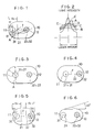
- Fig. 1 is a sectional view showing the arrangement of the first embodiment of the laser device.
- the laser device comprises: one axially symmetrical laser rod 12; one cylindrical pump lamp 11 arranged in parallel to and adjoining the laser rod 12; and the beam converger 10 having reflective surfaces including two partial cylindrical curved surfaces and two partial plain surfaces arranged plane-parallelly, said curved surfaces and said plain surfaces plane-parallelly, substantially uniformly surrounding the laser rod 12 and the pump lamp 11 in the axial direction thereof; wherein the center lines 21 and 22 of the partial cylindircal curved surfaces, the axis 32 of the laser rod 12 and the axis 31 of the pump lamp 11 are in one and the same plane, and the axis 32 of the laser rod 12 opposed to the partial cylindrical curved surface of the reflective surface is on the center line 22 of the partial cylindrical curved surface, while, the axis 31 of the pump lamp 11 being on a plane l connecting the center lines 21 and 22 to each other is shifted to a position closer to the partial cylindrical curved line than the center line 21 thereof.
- a characteristic curve A relates to the laser device as shown in Fig. 31 disclosed in Japanese Patent Unexamined Publication No. 51-40894, and the distribution of light intensity has a difference in height of about 65 %.
- a characteristic curve B relates to the comparative example in which the cross sectional shape of the beam converger 10 consists of half circles and straight-lines but not an ellipse as shown in Fig.
- the difference in height of the distribution of light intensity is improved to about 20 %.
- the total amount of light energy of the laser beam emanated from this comparative example is decreased by about 40 % as compared with the conventional example of Fig. 31.
- the distribution of light intensity has the difference in height of only about 20 %, thus highly improving the uniformity.
- the total amount of light energy of the laser beam emanated from the laser device according to this embodiment is increased by about 15 % as compared with the comparative example of Fig. 3.
- the inventors of the present invention studied the reason why the above-described high efficiency was achieved in the following way. Namely, in the compartive example shown in Fig. 3, the whole of light emitted to the left from a perpendicular line A out of rays emanated from the pump lamp 11 returns again to the pump lamp 11 and does not contribute to the absorption of the laser rod 12. In constrast thereto, when the axis 31 of the pump lamp 11 is shifted to the outer side (to the left of Fig. 1) of the center line 21 of one of circles of the beam converger 10 as in the first embodiment, the rays which have returned to the pump lamp 11 again in the comparative example shown in the Fig. 3 can be absorbed by the laser rod 12 as indicated by straight lines A and B. For this reason, in this embodiment, the light energy is not wasted as compared with the comparative example, as the result the high efficiency of the total amount of light energy can be achieved.
- the first embodiment has a favorable arrangement, and this fact seems to contribute to the high efficiency of the total amount of light energy.
- the axis 31 of the pump lamp 11 is moved to the outer side of the center line 21 of one of the half circles of the beam converger 10, so that the center lines 21 and 22 of the half circles can be made to approach to each other. Because of this, the beam converger 10, i.e., the laser device can be rendered compact by a dimension (R2 - R1) as compared with the comparative example shown in Fig. 3.
- Fig. 4 is the sectional view showing the arrangement of the second embodiment of the laser device.
- the axis 31 of the pump lamp 11 is placed on the center line 21 of the partial cylindrical curved surface opposed by the pump lamp 11, while, the axis 32 of the laser rod 12 is shifted to the position closer to the partial cylindrical curved surface than the center line 22 of the partial cylindrical curved surface opposed by the laser rod 12, on the plane l connecting the center lines 21 and 22.
- Fig. 5 is the sectional view showing the arrangement of the third embodiment of the laser device.
- the axis 31 of the pump lamp 11 not only the axis 31 of the pump lamp 11 but also the axis 32 of the laser rod 12 are positioned on an extension of the plane l connecting the center line 22 of one of the partial cylindrical curved surface surrounding the laser rod 12 to the center line 21 of the other of the partial cylindirical curved surface surrounding the pump lamp 11.
- the pump light reflected by the mirror surface of the beam converger 10 and directed to the laser rod 12 is spread in a large scope, so that the difference between maximum and minimum pump intensities in the laser rod 12 is reduced.
- the distribution of light intensity emitted from the laser rod 12 becomes one shown by a characteristic curve D in Fig. 2.
- This characteristic curve D has a difference in height of the distribution of light intensity of 25 %, and uniformity of light intensity is slightly deteriorated as compared with the case of the aforesaid first embodiment (about 20 %).
- the total amount of light intensity is increased by about 25 % as compared with the comparative example shown in Fig. 3.
- This third embodiment is rendered compact by a dimension of 2 x (R2 - R1) as compared with the comparative example shown in Fig. 3.
- Fig. 6 is the sectional view showing the arrangement of the fourth embodiment of the laser device.
- an angle of aperture of about 20° is formed between planes forming the beam converger 10 and a plane connecting the center line 21 of the partial cylinder surrounding the pump lamp 11 to the center line 22 of the partial cylinder surrouding the laser rod 12.
- this embodiment is obtained by improving the first embodiment, however, the present invention should not be limted to this, and embodiments may be obtained by improving the second or third embodiment.
- Fig. 7 is the sectional view showing the arrangement of the fifth embodiment of the laser device.
- one more pump lamp 13 is added to the side opposite to the pump lamp 11, whereby the laser rod 12 is excited from both sides by the pump lamps 11 and 13.
- the center lines 21 and 23 of the partial cylinders of the beam converger 10 surrounding the pump lamp 11 and 13, repectively, are positioned on a plane connecting the axes 31 and 33 of the pump lamps 11 and 13 to the axis 32 of the laser rod 12, and shifted to a position between the axes 31 and 33 (the side closer to the laser rod 12).
- the laser rod 12 is positioned at the center on a plane connecting the axes 31 and 33 of the two pump lamps 11 and 13.
- the laser rod 12 is excited from the both sides, so that uniformity of laser intensity in its cross section is improved. Further, with the arrangement according to the present invention, for the reason that is described in the first embodiment, the distribution of light intensity which has had the difference in height of about 65 % in the conventional example as shown in Fig. 32, is improved to about 20 %, and the total amount of light energy is increased by about 15 % as compared with the comparative example wherein the axes 31 and 33 of both the pump lamps 11 and 13 are positioned on the center lines 21 and 23 of the partial cylinders as shown in Fig. 8. In addition, this fifth embodiment is rendered compact in size by a dimension of 2 x (R2 - R1) as compared with the comparative example shown in Fig. 8.
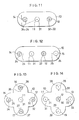
- Fig. 9 is the sectional view showing the arrangement of the sixth embodiment of the laser device.
- one more laser rod 14 is added to the side opposite to the laser rod 12, whereby the two laser rods 12 and 14 are excited by one pump lamp 11.
- the center lines 22 and 24 of the partial cylinders of the beam converger 10 surrounding the laser rods 12 and 14, respectively, are positioned on an extension of a plane connecting the axes 32 and 34 of the laser rods 12 and 14 to the axis 31 of the pump lamp 11.
- the pump lamp 11 is positioned at the center on a plane connecting the axes 32 and 34 of the two laser rods 12 and 14 to each other.
- the pump light reflected by the mirror surface of the beam converger 10 widely excites the surfaces of the laser rods 12 and 14, whereby the distribution of light intensity emitted from the laser rods 12 and 14 forms a moderate curve as indicated by a characteristic curve F shown in Fig. 10.
- the characteristic curve A relates to the conventional laser device as shown in Fig. 33 disclosed in Japanese Patent Unexamined Publication No. 50-85291 and has the difference in height of the distribution of light intensity of about 65 %.
- the characteristic curve B relates to the comparative example wherein the axes 32 and 34 of both the laser rods 12 and 14 are positioned on the center lines 22 and 24 of the partial cylinders, as shown in Fig. 11.
- the difference of the distribution of light intensity is improved to about 20 %.
- the total amount of light energy of the laser beam emitted from the laser device in the comparative example of Fig. 11 is decreased by about 40 % as compared with the aforesaid conventional example (the characteristic curve A).
- the distribution of light intensity has only the difference in height of about 20 %, so that the intensity distribution is highly improved.
- the total amount of light intensity of the laser beam emitted from the laser device in this embodiment is increased by about 15 % as compared with the comparative example shown in Fig. 11.
- the position where the distribution of light intensity in the comparative example in Fig. 11 (curve B) reaches the highest is greatly shifted from the center of the laser medium.
- the position where the distribution of light intensity in the case of the sixth embodiment (curve F) reaches the highest is close to the center of the laser medium.
- the inventors of the present invention studied the reason why the non-symmetrical property of the distribution of light intensity was improved and the high efficiency was achieved as described above in the following way. Namely, in the comparativae example shown in Fig. 11, the laser rods 12 and 14 are intensively excited from their surfaces directed toward the pump lamp 11. As shown in one example in the drawings, the light which has been incident on the cylindrical portion of the beam converger 10 goes away without being thrown onto the laser rod 14, and therefore, does not contribute to the excitation. On the other hand, in the sixth embodiment, the light similar to the above is thrown onto the laser rod 14 as shown in Fig. 9, and therefore, contributes to the excitation. As the result, the non-symmetrical property is more improved than in the case of the comparative example, thus achieving a high efficiency.
- the center lines 22 and 24 of the partial cylinders of the beam converger 10 are moved to the inner side of the axes 32 and 34 of the laser rods 12 and 14, so that the center lines 22 and 24 of the partial cylinders of the beam converger 10 can be brought to be close by the amount of moving. Because of this, the beam converger 10, i.e., the laser device can be rendered compact in size by a dimension of 2 x (R2 - R1) as compared with the case of the comparative example in Fig. 11.
- This embodiment is most suitable when the two laser rods 12 and 14 in a single laser device are to used as a laser oscillator and a laser amplifier, respectively, so that the laser device can be rendered compact in size.
- Fig. 12 is the sectional view showing the seventh embodiment of the laser device.
- one more pump lamp 15 is added to the right side of the laser rod 12, so that the laser rod 12 can be excited by the two pump lamps 11 and 15.
- the axis 35 of the pump lamp 15 is positioned on an extension of a plane connecting the center line 25 of the partial cylinder surrounding the pump lamp 15 to the axis 32 of the laser rod 12.
- the laser rod 14 can be used as an oscillator and the laser rod 12 can be used as an amplifier.
- the rate of amplification of the amplifier can be desirably varied by changing the electric input energy of the added pump lamp 15.
- Fig. 13 is the sectional view showing the arrangement of the eighth embodiment of the laser device.
- two laser rods 16 and 17 are added upwardly and downwardly of the pump lamp 11, respectively, whereby the four laser rods 12, 14, 16 and 17 are excited by the single common pump lamp 11.
- the axes 36 and 37 of the laser rods 16 and 17 are positioned on an extension of a plane connecting the center lines 26 and 27 of the partial cylinders respectively surrounding the laser rods 16 and 17 to the axis 31 of the pump lamp 11.
- This embodiment is most suitable when one of the laser rod is used as an oscillator and the remaining three laser rods are used as amplifiers, respectively, so that multiple stage amplification can be conducted.
- Fig. 14 is the sectional view showing the arrangement of the ninth embodiment of the laser device.
- the axes 38 and 39 of the pump lamps 18 and 19 are positioned on an extension of a plane connecting the center lines 28 and 29 of the partial cylinders respectively surrounding the pump lamps 18 and 19 to the axis 32 of the laser rod 12.
- respective outer diameters of the pump lamps 11, 13, 15, 18 and 19 are substantially equal to those of the laser rods 12, 14, 16 and 17.
- the relationship between the sizes of the pump lamps and those of the laser rods should not necessary limited to this.
- the outer diameter of the pump lamp is small, since the pump lamp is seen as a point light source, the beam converging property of the beam converger is raised. Although the distribution of light intensity becomes slightly ununiform, the efficiency of energy is improved. In addition, it becomes possible to bring the reflective surface of the beam converger 10 to a position close to the diameter of the laser rod, thereby advantageously render the laser device compact in size.
- Fig. 15 is the sectional view showing the arrangement of the tenth embodiment of the laser device.
- the pump lamp 11 which has a smaller outer diameter than the diameter of the laser rod 12 is used.
- Other details are smimilar to those of the first embodiment, and therefore, the description will be omitted.
- the distribution of light intensity showed a moderate curve substantially similar to the curve C in Fig. 2, the difference in height was about 22 %, and the distribution of energy was not so deteriorated.
- the efficiency of energy was better than one in the first embodiment and was increased by 20 % from that of the comparative example shown in Fig. 3.
- the laser device can be rendered compact in size without changing the energy efficiency and the difference in height of the energy distribution.
- Fig. 17 is the sectional view showing the arrangement of the eleventh embodiment of the laser device.
- the pump lamp 11 which has an outer diameter smaller than the diameter of the laser rod 12 is used.
- Other details are similar to those of the third embodiment, and therefore, the description will be omitted.
- the distribution of light intensity showed a moderate curve substantially similar to the curve D shown in Fig. 2, the difference in height is about 27 %, and the efficiency of energy is higher by 28 % than that of the comparative example in Fig. 3.
- Fig. 18 is the sectional view showing the arrangement of the twelfth embodiment of the laser device.
- the two pump lamps 11 and 13 which have the outer diameters smaller than the diameter of the laser rod 12 are used.
- Other details are similar to those of the fifth embodiment, and therefore, the description will be omittd.
- the difference in height of the distribution of light intensity is 22 % and the efficiency of energy is increased by 20 % as compared with that of the conventional example in Fig. 32.
- Fig. 19 is the sectional view showing the arrangement of the thirteenth embodiment of the laser device.
- the outer diameter of the pump lamp 11 is smaller than the diameters of the laser rods 12 and 14, and the outer diameter of the pump lamp 15 is further smaller than the outer diameter of the pump lamp 11. Furthermore, the axis 34 of the laser rod 14 is made to coincide with the axis 24 of the partial cylinder. Other details are similar to those of the seventh embodiment, and therefore, the description will be omitted.
- the distribution of light intensity of the laser rod 14 showed a moderate curve between the curves B and F in Fig. 10 and the efficiency of energy was increased by 5 % as compared with the comparative example showin in Fig. 11.
- the difference in height of energy efficiency of the laser rod 12 was 22 %, while the efficiency of energy was increased 20 % as compared with that of the comparative example shown in Fig. 11.
- the outer diameter of the pump lamp 15 is made smaller than that of the pump lamp 11 in this embodiment resides in that the pump lamp 11 excites the two laser rods 12 and 14, whereas the pump lamp 15 excites only the laser rod 12. Particularly, in the case where the laser rod 12 is used as an amplifier and the pump lamp 15 is used for gain control thereof, the outer diameter of the pump lamp 15 may be small.
- Fig. 20 is the sectional view showing the arrangement of the fourteenth embodiment of the laser device.
- the pump lamps 11, 13, 18 and 19 have outer diameters smaller than that of the laser rod 12. Other details are similar to those of the ninth embodiment, and therefore, the description will be omitted.
- the distribution of light intensity of the laser rod 12 showed a moderate curve substantially similar to the curve F in Fig. 10.
- the energy efficiency was further increased by about 5 % as compared with that of the ninth embodiment.
- the pump lamps 11, 13, 15, 18 and 19 cylindrical ones are used and as the laser rods 12, 14, 16 and 17, solid columnar rod shaped ones are used, however, the shapes of the pump light sources and laser media should not necessarily be limited to these.
- hollow columnar laser media disclosed in USP 4751716 may be used.
- a Nd: YAG was mainly used as the laser rod.
- laser media should not necessarily be limited to Nd: YAG.
- Nd: Glass, Er: YAG, Nd: YSGG and Ruby can give similar results.
- Fig. 21 is the optical path diagram showing the general arrangement of the first embodiment according to the present invention relating to the laser system.
- same reference numerals as shown in Fig. 30 are used to designate same or similar parts. Therefore, overlapped description will be avoided here.
- a dielectric multi-layer film for example, is deposited on portions of inclined surfaces of a prism 101a having a rectangular equilateral triangle shape in cross section, and a half-transmittable film 101b is formed.
- the laser device 120 there is used the one having the two pump lamps 11 and 15 and the two laser rods 12 and 14 as shown in the thirteenth embodiment in Fig. 19 and in the seventh embodiment shown in Fig. 12.
- the laser device having one pump lamp 11 and two laser rods 12 and 14 as shown in the sixth embodiment in Fig. 9, the comparative example shown in Fig. 11 and the conventional example shown in Fig. 32.
- the laser oscillator is constituted by the half-transmittable film 101b of the output mirror 101, the laser rod 14 of the laser device 120 and the total reflection mirror 5.
- the laser beams emitted from the laser oscillator are reflected regularly twice by the prism 101a and thus reflected in a direction opposite to the incident direction.
- the reflected beams (laser beams) are led to the laser rod 12 of the laser device 120, where the beams are amplified, therefore, the beams are reflected regularly by the prism 6e for example, and thrown to the body to be measured, not shown, or the like.
- the output mirror 101 in this embodiment is usable.
- Fig. 22 is the sectional view showing the arrangement of another example of the output mirror 101.
- an anti-reflection film 110 is attached to a portion of the inclined surfaces of the prism 101a having the rectangular equilateral triangle shape in cross section (more specifically, a remaining portion of a part where the half-transmittable film 101b is formed).
- Fig. 23 is the sectional view showing another example of the cross section of the prism 101a used in the output mirror 101.
- a prism 101c having a partial shape thereof, i.e., a trapezoidal shape in cross section (a shape in which a small triangle at the portion of the right angle is removed from the regular equilateral triangle shape) may be used.
- the prism 101c since the laser beams emitted from the laser oscillator are reflected regularly by the inclined surface portions of the trapezoid of a prism 101c shown in Fig. 23, the prism 101c has the function similar to that of the prism 101a shown in the examples of Figs. 21 and 22.
- the number of the optical elements is small as compared with the conventional example shown in Fig. 30, adjustment of many optical elements such as the half mirror 9 and the prisms 6a - 6d is not necessary, and adjustment of the optical axes of the optical elements can be facilitated.
- the installation space of the output mirror 101 is by far smaller than the installation space of the half mirror 9 and the prisms 6a - 6d, thus improving the space factor.
- the laser system using the above-described output mirror 101 can be rendered compact in size.
- adjustment of the optical axes of the optical elements in the above-described laser system and the like is made easy, with the result that an easily usable laser system is realized.
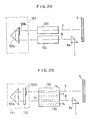
- Fig. 24 is the optical path diagram showing the general arrangement of the second embodiment of the present invention relating to the laser system.
- independent laser devices 123 and 124 for oscillating and amplifying, respectively, are used in place of the common laser device 120 in the first embodiment.
- the laser devices 123 and 124 there may be used those shown in the first embodiment shown in Fig. 1, shown in the comparative examples in Figs. 3 and 8, shown in the second to fifth embodiments in Figs. 4 to 7, shown in the ninth and tenth embodiments in Figs. 14 and 15, shown in the modification thereof in Fig. 16, shown in the eleventh and twelfth embodiments in Figs. 17 and 18, shown in the fourteenth embodiment in Fig. 20 and shown in the conventional examples in Figs. 31, 32 and 34 for example, in all of which one or a plurality of pump lamps 11... and one laser rod 12 are provided.
- this second embodiment is similar to those of the first embodiment except for the laser devices 123 and 124. Therefore, the detailed description will be omitted.
- Fig. 25 is the optical path diagram showing the general arrangement of the third embodiment according to the present invention relating to the laser system.
- same reference numerals are used to designate the same or similar parts in Fig. 21. Therefore, overlapped description will be avoided.
- the output mirror 111 as being the essential portion of this embodiment is constituted by the prism 101a similar to the one in the first embodiment and an optical substrate 112 provided at the side of a laser path of the prism 101a and deposited on the surface of the incident laser path portion thereof (upwardly in the drawing) with a dielectric multi-layer film so as to form a half-transmittable film 101d.
- the optical substrate 112 deposited thereon with the half-transmittable film 101d, the laser rod 14 of the laser device 120 and the total reflection mirror 5 constitute a laser oscillator.
- the laser beams emitted from the above-described laser oscillator are reflected regularly twice by the prism 101a and reflected in a direction opposite to the incident direction.
- the reflected beams (laser beams) are transmitted through a transparent portion of the optical substrate 112 (downwardly in the drawing), therefore, led to the laser rod 12, where the reflected beams are amplified, thereupon, the amplified beams are reflected regularly by the prism 6e and thrown to the body to be measured, not shown, or the like.
- the output mirror 111 of this embodiment is usable.
- Fig. 26 is the sectional view showing another example of the output mirror 111.
- anti-reflection films 113a, 113b and 113c are respectively attached to the inclined surface of the prism 101a having the regular equilateral triangle shape in cross section (other two surfaces as necessary), the rear surface of the optical substrate 112 and a portion of the front surface of the optical substrate 112 (downwardly in the drawing).
- the so-called phenomenon of return of ight in which the laser beams emitted from the laser oscillator (more specifically, the half-transmittable film 101d) return to the laser oscillator again is avoided by the anti-reflection films 113a - 113c, and the loss of the laser beams can be effectively prevented.
- Fig. 27 is the sectional view showing a further example of the output mirror 111.
- 114 designates an optical substrate, and a dielectric multi-layer film is deposited on the surface of the optical substrate 114 to form a half-transmittable film 101d which serves as a half mirror.
- the shape of the front of the optical substrate 114 formed on the surface thereof with the half-transmittable film 101d is semicircular as shown in Fig. 28.
- the shape of the front of the optical substrate (half-mirror) 114 is semicircular, even if the optical axes 7 and 8 in Fig. 25 are close to each other, the laser beams emitted from the laser rod 14 for oscillating can be effectively led to the laser rod 12 for amplifying.
- anti-reflection films similar to those shown the example in Fig. 26 are attached to the rear surface of the optical substrate 114 and the inclined surface portion of the prism 101a, so that the return of light of the laser beams emitted from the laser oscillator and the loss of the laser beams can be efficiently prevented.
- the number of the optical elements is small as compared with the conventional example shown in Fig. 30 and adjustment of the optical axes of these optical elements can be made easy.
- the installation space of the output mirror 111 is by far smaller than the installation space of the half-mirror 9 and the prims 6a - 6d in the conventional example shown in Fig. 30 and the space factor is highly improved.
- the laser system using the output mirror 111 can be rendered compact in size.
- adjustment of the optical axes and the like in the laser system described above is easily made, with the result that an easily usable laser system can be realized.
- Fig. 29 is the optical path diagram showing the general arrangement of the fourth embodiment of the present invention relating to the laser system.
- independent laser devices 123 and 124 for oscillating and amplifying, respectively, which are similar to those shown in the second embodiment are used in place of the laser device 120 in the third embodiment.
- This embodiment has the arrangement similar to that in the third embodiment except for the laser devices 123 and 124, and therefore, detailed description will be omitted.
Landscapes
- Physics & Mathematics (AREA)
- Electromagnetism (AREA)
- Engineering & Computer Science (AREA)
- Plasma & Fusion (AREA)
- Optics & Photonics (AREA)
- Lasers (AREA)
Applications Claiming Priority (8)
| Application Number | Priority Date | Filing Date | Title |
|---|---|---|---|
| JP22165788 | 1988-09-05 | ||
| JP221657/88 | 1988-09-05 | ||
| JP227778/88 | 1988-09-12 | ||
| JP22777888 | 1988-09-12 | ||
| JP16908089A JPH02168685A (ja) | 1988-09-05 | 1989-06-30 | 出力鏡及びその出力鏡を用いたレーザシステム |
| JP16908189 | 1989-06-30 | ||
| JP169080/89 | 1989-06-30 | ||
| JP169081/89 | 1989-06-30 |
Publications (3)
| Publication Number | Publication Date |
|---|---|
| EP0358464A2 true EP0358464A2 (fr) | 1990-03-14 |
| EP0358464A3 EP0358464A3 (en) | 1990-05-02 |
| EP0358464B1 EP0358464B1 (fr) | 1994-06-15 |
Family
ID=27474240
Family Applications (1)
| Application Number | Title | Priority Date | Filing Date |
|---|---|---|---|
| EP89308994A Expired - Lifetime EP0358464B1 (fr) | 1988-09-05 | 1989-09-05 | Dispositifs laser et système à laser incluant les dispositifs laser |
Country Status (4)
| Country | Link |
|---|---|
| US (1) | US4993038A (fr) |
| EP (1) | EP0358464B1 (fr) |
| CA (1) | CA1320559C (fr) |
| DE (1) | DE68916136T2 (fr) |
Cited By (1)
| Publication number | Priority date | Publication date | Assignee | Title |
|---|---|---|---|---|
| DE4105717A1 (de) * | 1991-02-23 | 1992-08-27 | Aesculap Ag | Laser |
Families Citing this family (12)
| Publication number | Priority date | Publication date | Assignee | Title |
|---|---|---|---|---|
| US5172388A (en) * | 1991-07-23 | 1992-12-15 | International Business Machines Corporation | Method and apparatus for an increased pulse repetition rate for a CW pumped laser |
| JPH06104515A (ja) * | 1992-09-21 | 1994-04-15 | Kokusai Denshin Denwa Co Ltd <Kdd> | 固体レーザ |
| US5548604A (en) * | 1993-03-19 | 1996-08-20 | Toepel; Michael P. | Compact hand held medical device laser |
| JP3265173B2 (ja) * | 1995-01-10 | 2002-03-11 | 三菱電機株式会社 | 固体レーザ装置 |
| US5867518A (en) * | 1996-08-07 | 1999-02-02 | Lumonics Inc. | Multiple element laser pumping chamber |
| CN1109388C (zh) * | 1998-01-06 | 2003-05-21 | 中国人民解放军武汉军械士官学校 | 免调试固体激光装置 |
| US6385227B1 (en) * | 1999-01-12 | 2002-05-07 | Kabushiki Kaisha Toshiba | Solid-state laser apparatus and laser process apparatus |
| US6490081B1 (en) * | 2000-07-28 | 2002-12-03 | The Board Of Trustees Of The Leland Stanford Junior University | Method of amplifying optical signals using doped materials with extremely broad bandwidths |
| JP2011512035A (ja) * | 2008-02-05 | 2011-04-14 | レーザー エナジェティックス,インコーポレイテッド | 励起チャンバ集積ランプ |
| DE102011103286A1 (de) * | 2011-06-04 | 2012-12-06 | Roland Berger | Anregungseinheit für einen Faserlaser |
| RU182531U1 (ru) * | 2017-12-21 | 2018-08-22 | Акционерное общество "Научно-исследовательский институт "Полюс" им. М.Ф. Стельмаха" | Твердотельный лазер |
| RU183902U1 (ru) * | 2017-12-21 | 2018-10-08 | Акционерное общество "Научно-исследовательский институт "Полюс" им. М.Ф. Стельмаха" | Охлаждаемый твердотельный лазер |
Family Cites Families (8)
| Publication number | Priority date | Publication date | Assignee | Title |
|---|---|---|---|---|
| US3967215A (en) * | 1966-04-29 | 1976-06-29 | Bellak Johannes G | Laser reactor |
| DE1614613A1 (de) * | 1967-09-28 | 1970-07-02 | Siemens Ag | Beleuchtungseinrichtung fuer optische Molekularverstaerker |
| US3646474A (en) * | 1969-04-21 | 1972-02-29 | American Optical Corp | Symmetrically pumped slab laser |
| US4439861A (en) * | 1981-08-07 | 1984-03-27 | Mrj, Inc. | Solid state laser with controlled optical pumping |
| US4751716A (en) * | 1986-05-01 | 1988-06-14 | Amada Engineering & Service Co., Inc. | Hollow cylindrical solid state laser medium and a laser system using the medium |
| EP0271809B1 (fr) * | 1986-12-08 | 1990-09-05 | Mitsubishi Denki Kabushiki Kaisha | Appareil laser |
| US4802186A (en) * | 1987-07-06 | 1989-01-31 | Hughes Aircraft Company | High reflectance laser resonator cavity |
| JPH0585291A (ja) * | 1991-09-27 | 1993-04-06 | Asahi Chem Ind Co Ltd | エアーバツグの製造方法 |
-
1989
- 1989-09-01 CA CA000610201A patent/CA1320559C/fr not_active Expired - Fee Related
- 1989-09-01 US US07/401,922 patent/US4993038A/en not_active Expired - Fee Related
- 1989-09-05 EP EP89308994A patent/EP0358464B1/fr not_active Expired - Lifetime
- 1989-09-05 DE DE68916136T patent/DE68916136T2/de not_active Expired - Fee Related
Cited By (1)
| Publication number | Priority date | Publication date | Assignee | Title |
|---|---|---|---|---|
| DE4105717A1 (de) * | 1991-02-23 | 1992-08-27 | Aesculap Ag | Laser |
Also Published As
| Publication number | Publication date |
|---|---|
| EP0358464A3 (en) | 1990-05-02 |
| US4993038A (en) | 1991-02-12 |
| DE68916136T2 (de) | 1994-09-22 |
| DE68916136D1 (de) | 1994-07-21 |
| EP0358464B1 (fr) | 1994-06-15 |
| CA1320559C (fr) | 1993-07-20 |
Similar Documents
| Publication | Publication Date | Title |
|---|---|---|
| JP3589299B2 (ja) | ビーム整形装置 | |
| EP0358464A2 (fr) | Dispositifs laser et système à laser incluant les dispositifs laser | |
| JPH11504130A (ja) | 単数または複数の固体レーザおよび/または半導体レーザの照射野を形成し案内する装置とその方法 | |
| CA2047086C (fr) | Reflecteur-diffuseur | |
| US5432811A (en) | Laser rod with polyhedron shaped ends | |
| KR101033759B1 (ko) | 반도체 레이저 장치 | |
| US6160934A (en) | Hollow lensing duct | |
| RU99105608A (ru) | Лазерное устройство | |
| US5216687A (en) | Solid state laser device with a bi-cylindrical covexo-convex lens having selected radii of curvature to preferably pump a region of a laser medium | |
| US6351477B1 (en) | Optically pumped intensifying agent, in particular a solid intensifying agent | |
| US5349603A (en) | Solid-state laser resonator | |
| JPH01100983A (ja) | 固体レーザにおけるレーザロッド励起装置 | |
| KR101048982B1 (ko) | 반도체 레이저 장치 | |
| EP1766442A1 (fr) | Ensemble diaphragme pour faisceaux laser de grande puissance | |
| JPH0918072A (ja) | 固体レーザ | |
| US6433928B1 (en) | Optical amplifier, optical amplification apparatus, and optical amplification method | |
| JPH07287104A (ja) | 光路変換器及び光路変換アレイ | |
| KR100257401B1 (ko) | 출력조절식 레이저 광 발생장치 | |
| JPH07287189A (ja) | 光路変換器およびそれを用いたレーザ装置 | |
| JPH0387083A (ja) | レーザ装置 | |
| JPS60242685A (ja) | ガスレ−ザ | |
| RU2027267C1 (ru) | Газовый лазер | |
| JP3383217B2 (ja) | 固体レーザ装置 | |
| JP2576794B2 (ja) | レーザダイオード励起固体レーザ発振装置 | |
| JPH0473702A (ja) | 拡散反射体 |
Legal Events
| Date | Code | Title | Description |
|---|---|---|---|
| PUAI | Public reference made under article 153(3) epc to a published international application that has entered the european phase |
Free format text: ORIGINAL CODE: 0009012 |
|
| PUAL | Search report despatched |
Free format text: ORIGINAL CODE: 0009013 |
|
| AK | Designated contracting states |
Kind code of ref document: A2 Designated state(s): DE FR GB |
|
| AK | Designated contracting states |
Kind code of ref document: A3 Designated state(s): DE FR GB |
|
| 17P | Request for examination filed |
Effective date: 19900813 |
|
| 17Q | First examination report despatched |
Effective date: 19920731 |
|
| GRAA | (expected) grant |
Free format text: ORIGINAL CODE: 0009210 |
|
| AK | Designated contracting states |
Kind code of ref document: B1 Designated state(s): DE FR GB |
|
| REF | Corresponds to: |
Ref document number: 68916136 Country of ref document: DE Date of ref document: 19940721 |
|
| PGFP | Annual fee paid to national office [announced via postgrant information from national office to epo] |
Ref country code: LU Payment date: 19940901 Year of fee payment: 6 |
|
| ET | Fr: translation filed | ||
| PLBE | No opposition filed within time limit |
Free format text: ORIGINAL CODE: 0009261 |
|
| STAA | Information on the status of an ep patent application or granted ep patent |
Free format text: STATUS: NO OPPOSITION FILED WITHIN TIME LIMIT |
|
| 26N | No opposition filed | ||
| PGFP | Annual fee paid to national office [announced via postgrant information from national office to epo] |
Ref country code: GB Payment date: 19990901 Year of fee payment: 11 |
|
| PGFP | Annual fee paid to national office [announced via postgrant information from national office to epo] |
Ref country code: DE Payment date: 19990906 Year of fee payment: 11 |
|
| PGFP | Annual fee paid to national office [announced via postgrant information from national office to epo] |
Ref country code: FR Payment date: 19990909 Year of fee payment: 11 |
|
| PG25 | Lapsed in a contracting state [announced via postgrant information from national office to epo] |
Ref country code: GB Free format text: LAPSE BECAUSE OF NON-PAYMENT OF DUE FEES Effective date: 20000905 |
|
| GBPC | Gb: european patent ceased through non-payment of renewal fee |
Effective date: 20000905 |
|
| PG25 | Lapsed in a contracting state [announced via postgrant information from national office to epo] |
Ref country code: FR Free format text: LAPSE BECAUSE OF NON-PAYMENT OF DUE FEES Effective date: 20010531 |
|
| PG25 | Lapsed in a contracting state [announced via postgrant information from national office to epo] |
Ref country code: DE Free format text: LAPSE BECAUSE OF NON-PAYMENT OF DUE FEES Effective date: 20010601 |
|
| REG | Reference to a national code |
Ref country code: FR Ref legal event code: ST |