EP0358541A1 - Hub- und Verriegelungsvorrichtung für eine Last oder einen Behälter auf einem Fahrzeug - Google Patents
Hub- und Verriegelungsvorrichtung für eine Last oder einen Behälter auf einem Fahrzeug Download PDFInfo
- Publication number
- EP0358541A1 EP0358541A1 EP89402178A EP89402178A EP0358541A1 EP 0358541 A1 EP0358541 A1 EP 0358541A1 EP 89402178 A EP89402178 A EP 89402178A EP 89402178 A EP89402178 A EP 89402178A EP 0358541 A1 EP0358541 A1 EP 0358541A1
- Authority
- EP
- European Patent Office
- Prior art keywords
- chassis
- hook
- intermediate arm
- locking
- arm
- Prior art date
- Legal status (The legal status is an assumption and is not a legal conclusion. Google has not performed a legal analysis and makes no representation as to the accuracy of the status listed.)
- Granted
Links
- 210000003323 beak Anatomy 0.000 description 11
- 235000003434 Sesamum indicum Nutrition 0.000 description 4
- 244000000231 Sesamum indicum Species 0.000 description 4
- 230000000694 effects Effects 0.000 description 2
- 230000001154 acute effect Effects 0.000 description 1
- 238000006073 displacement reaction Methods 0.000 description 1
- 238000009434 installation Methods 0.000 description 1
- 238000004519 manufacturing process Methods 0.000 description 1
- 238000000034 method Methods 0.000 description 1
Images




Classifications
-
- B—PERFORMING OPERATIONS; TRANSPORTING
- B60—VEHICLES IN GENERAL
- B60P—VEHICLES ADAPTED FOR LOAD TRANSPORTATION OR TO TRANSPORT, TO CARRY, OR TO COMPRISE SPECIAL LOADS OR OBJECTS
- B60P1/00—Vehicles predominantly for transporting loads and modified to facilitate loading, consolidating the load, or unloading
- B60P1/64—Vehicles predominantly for transporting loads and modified to facilitate loading, consolidating the load, or unloading the load supporting or containing element being readily removable
- B60P1/6418—Vehicles predominantly for transporting loads and modified to facilitate loading, consolidating the load, or unloading the load supporting or containing element being readily removable the load-transporting element being a container or similar
- B60P1/6463—Vehicles predominantly for transporting loads and modified to facilitate loading, consolidating the load, or unloading the load supporting or containing element being readily removable the load-transporting element being a container or similar fitted with articulated beams for longitudinal displacement of the container
Definitions
- the invention relates to a lifting device associated with a utility vehicle for maneuvering and locking a load.
- the maneuvering devices with articulated arms which equip trucks are primarily intended to move a bucket, loaded or not; ie take it to the ground to place it on a truck, and reverse maneuver. Finally, when the body is full, allow an arm-to-body tilt to empty the load.
- the best known devices to date include a lower tipper articulated at the rear of the truck, an intermediate lifting arm and a front hooking arm which ends in a gripping hook adapted to take the front of a bucket, one or more cylinders are associated between the chassis of the truck and the lifting arm to allow the various maneuvering movements to be combined appropriately.
- the tipping is carried out by locking the lower tipper to the chassis of the bucket to pivot securely on the rear articulation.
- the devices most used at the present time have been designed with kinematics capable of carrying out only maneuvers of tippers manufactured in the form of a body with four right angles, welded on various chassis of standard form.
- Ansi over the years, are found in the same park long and short skips, flared or straight.
- These skips are mounted on chassis generally made of IPN or UPN arranged both with the inner and outer wings to such an extent that the handling and transport of these skips has become in certain cases particularly delicate in terms of safety.
- the present invention proposes to provide a solution to the problems posed above and to provide an improved maneuvering device, capable of ensuring the appropriate interlocks for carrying out laying, transporting and tipping operations in good conditions of security.
- Another objective of the invention is to increase the possibilities of the device by allowing it to load both short or long loads or skips, flared or straight.
- the device covered by the invention associated with an industrial vehicle and a load or bucket to enable the latter to be lifted and locked, is of the type comprising:
- At least two articulated arms one after the other constituted by a rocker articulated by one end at the rear of a carrier vehicle and a fastening member composed of an intermediate part and a part front, provided with a gripping hook and carried by its intermediate part so as to form therewith an angular profile, with a faculty of longitudinal movement of the said gripping hook relative to the said intermediate part, - means for pivoting the intermediate part on the rear rocker, means for longitudinal displacement of the front part, making it possible to move the gripping hook from the rear towards the front, offering a wide range of possibilities, - Locking means adapted to allow the lower rocker to be secured either with the body of the bucket or with the chassis of the carrier vehicle.
- the locking means comprise, for each side of the rocker:
- a double hook articulated on the external part of the rocker a single hook articulated on the same plane opposite, associated with an articulated connecting rod: at its lower part in the double hook, at its upper part at the upper part of a pendulum itself articulated at an intermediate point in the single hook, the lower part of this so-called pendulum is articulated to a double-acting cylinder to actuate the mechanism in two situations.
- the two wings are pinched at the same time by the upper beak of the double hook and the beak of the single hook.
- the operation of the double hook and of its opposite the single hook is obtained under the action of a short jack with double effect coupled directly on the two hooks, thus giving autonomy to a locking block. to be placed on either side of the lower rocker.
- the invention therefore takes advantage of equipment and procedures which have now become conventional, to increase the possibilities of lifting and maneuvering and to increase the locking and execution safety actions without any structural complication.
- Another objective of the invention is to improve the aforementioned means of lifting and maneuvering the gripping hook and to propose an embodiment of said means having appreciable advantages compared to known means of movement.
- the auxiliary cylinder is arranged in the plane of the intermediate part and is coupled, on the one hand, to this intermediate part, on the other hand, to a connecting rod arranged to be able to exert a traction or a push on the front part in order to cause it to pivot respectively backwards to form an acute angle with said intermediate part, or forwardly to form an obtuse angle.
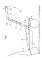
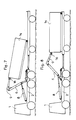
- the device shown by way of example in Figures 1,2,3,4,5 6 and 7, is intended to equip an industrial vehicle or truck 1 provided with a chassis 2, which traditionally supports a false chassis (we will therefore assimilate this false chassis to the chassis proper, the assembly being designated by the term truck chassis 2).
- the buckets 14 are built additionally on chassis 15 mainly made of IPN or UPN arranged on edge, the front part of the grab has an axis 16 for its gripping.
- Figures 9,10,11 and 12 are the illustration of the locking device according to the invention, corresponding to section AA in Figure 1 and 3 explaining the different possibilities of the means according to each case cited by way of example.
- FIG. 13, is the illustration of the same locking device in the form of an autonomous block.
- This locking device comprises for the essentials, a double hook 5 articulated 16 on the lower rocker 3 arranged opposite a simple hook 17 articulated 18 on the same plane, and controlled by a link rod 19 articulated 20 at one end in the double hook 5 and at the other end 21 at the top of a balance 22 which balance is articulated 23 at an intermediate point in the hook 17 and is coupled at its base 24 to a jack 25 with double effect transversely arranged to operate the right and left devices simultaneously.
- a short double-acting cylinder 26 is coupled directly between the double hook 5 and the single hook 17, the simultaneous approximation operation is ordered by hydraulic pressure.
- the jack 25 is in the traction position actuating the opening of the compasses formed by the pendulums 22 in association with the rods 19, which compasses act in thrust on the hooks 5 and 17 for the opening spouts which release the skip chassis 15 in this same movement the lower spouts of the double hooks 5 pinch the upper edge of the truck chassis 2, the skip chassis 15 and the intermediate arm 6 of the lifting device are then released to carry out a any maneuver, Figures 1,2,4 and 7.
- an intermediate arm 6 itself articulated 11 to a frame 9 which supports the hook 10 for gripping.
- Two double-acting power cylinders such as 8, are coupled to the front of the chassis 2 and to the intermediate arm 6 so as to operate the system.
- An auxiliary cylinder 13 is arranged in the intermediate part 6 and coupled, to said intermediate arm 6 and to a connecting rod 12 arranged to be able to exert a traction or a push on the gripping arm 9 until a support on the axis 11 in extension position.
- the front part, part 9 and gripping hook 10 can also be caused to pivot around the axis 11 forwards or backwards, as in FIGS. 5 and 6, or from top to bottom when the intermediate arm 6 is in a substantially vertical position as in Figures 1 and 4 for lifting a load.
- the connecting rod 12 has an elongated shape, under which is provided a curved part intended to come to bear on the axis 11 followed forwards by an upward curve, capable of bypassing the lower front angle of a bucket fig.3 and fig.6, then an extension to its point of articulation on the gripping arm 9 at a distance sufficiently spaced from the articulation 11 so as to transmit the full power of the auxiliary jack 13.
- the gripping arm 9 has a bent member at an obtuse angle at the base, capable of bypassing both a 90 ° angle of a conventional bucket fig.3 and an obtuse angle of a special bucket fig.6, up to '' to obtain an alignment of the lower elbow of the frame 9 with the intermediate arm 6 on either side of the articulation 11, fig.1 in the lifting position of a load and fig.6 during the transport of a special bucket, in this configuration the curved part of the connecting rod is supported on the upper part of the axis 11 arranged on either side.
Landscapes
- Engineering & Computer Science (AREA)
- Transportation (AREA)
- Mechanical Engineering (AREA)
- Forklifts And Lifting Vehicles (AREA)
- Handcart (AREA)
Applications Claiming Priority (2)
| Application Number | Priority Date | Filing Date | Title |
|---|---|---|---|
| FR8811782A FR2636280B1 (fr) | 1988-09-09 | 1988-09-09 | Dispositif de levage et de verrouillage d'une charge ou d'une benne sur un vehicule |
| FR8811782 | 1988-09-09 |
Publications (2)
| Publication Number | Publication Date |
|---|---|
| EP0358541A1 true EP0358541A1 (de) | 1990-03-14 |
| EP0358541B1 EP0358541B1 (de) | 1993-02-10 |
Family
ID=9369851
Family Applications (1)
| Application Number | Title | Priority Date | Filing Date |
|---|---|---|---|
| EP19890402178 Expired - Lifetime EP0358541B1 (de) | 1988-09-09 | 1989-08-01 | Hub- und Verriegelungsvorrichtung für eine Last oder einen Behälter auf einem Fahrzeug |
Country Status (3)
| Country | Link |
|---|---|
| EP (1) | EP0358541B1 (de) |
| DE (1) | DE68904845T2 (de) |
| FR (1) | FR2636280B1 (de) |
Cited By (6)
| Publication number | Priority date | Publication date | Assignee | Title |
|---|---|---|---|---|
| WO1994015813A1 (fr) * | 1993-01-13 | 1994-07-21 | Marc Deltomme | Dispositif pour vehicule de transport routier ou de man×uvre et vehicule equipe d'un tel dispositif |
| US5542808A (en) * | 1993-04-20 | 1996-08-06 | Marrel | Apparatus on a vehicle to pick up a load |
| EP1063122A1 (de) | 1999-06-21 | 2000-12-27 | Victoria Administration Limited | Vorrichtung zur Handhabung eines Behälters für ein Strassenfahrzeug |
| BE1012860A3 (nl) * | 1999-08-31 | 2001-04-03 | D T M International Nv | Vergrendelsysteem. |
| NL1017096C2 (nl) * | 2001-01-12 | 2002-07-15 | Hyva Internat Inc N V | Inrichting voor het verplaatsen van laadbakken. |
| EP1932717A1 (de) * | 2006-12-14 | 2008-06-18 | Guima Palfinger | Hydraulische Verschlussvorrichtung für einen Hubarm |
Families Citing this family (1)
| Publication number | Priority date | Publication date | Assignee | Title |
|---|---|---|---|---|
| GB9311634D0 (en) * | 1993-06-03 | 1993-07-21 | Spooner Edward | Electromagnetic machine |
Citations (4)
| Publication number | Priority date | Publication date | Assignee | Title |
|---|---|---|---|---|
| DE7718760U1 (de) * | 1977-06-14 | 1977-10-13 | Fa. Guima, Caussade (Frankreich) | Vorrichtung zur Bewegung eines Containers auf dem Chassis eines Fahrzeuges |
| EP0014513A1 (de) * | 1979-02-13 | 1980-08-20 | Constructiewerkhuizen MOL Gebroeders P.V.B.A. | Be- und Entlademechanismus für ein Container-Transportfahrzeug |
| GB2092993A (en) * | 1981-02-12 | 1982-08-25 | Partek Ab | Apparatus for loading and unloading an exchange platform or container onto and off a vehicle body |
| DE8410485U1 (de) * | 1984-04-04 | 1984-08-09 | Hüffermann, Rudolf, 2878 Wildeshausen | Wechselbehälteranhänger |
-
1988
- 1988-09-09 FR FR8811782A patent/FR2636280B1/fr not_active Expired - Fee Related
-
1989
- 1989-08-01 DE DE1989604845 patent/DE68904845T2/de not_active Expired - Fee Related
- 1989-08-01 EP EP19890402178 patent/EP0358541B1/de not_active Expired - Lifetime
Patent Citations (4)
| Publication number | Priority date | Publication date | Assignee | Title |
|---|---|---|---|---|
| DE7718760U1 (de) * | 1977-06-14 | 1977-10-13 | Fa. Guima, Caussade (Frankreich) | Vorrichtung zur Bewegung eines Containers auf dem Chassis eines Fahrzeuges |
| EP0014513A1 (de) * | 1979-02-13 | 1980-08-20 | Constructiewerkhuizen MOL Gebroeders P.V.B.A. | Be- und Entlademechanismus für ein Container-Transportfahrzeug |
| GB2092993A (en) * | 1981-02-12 | 1982-08-25 | Partek Ab | Apparatus for loading and unloading an exchange platform or container onto and off a vehicle body |
| DE8410485U1 (de) * | 1984-04-04 | 1984-08-09 | Hüffermann, Rudolf, 2878 Wildeshausen | Wechselbehälteranhänger |
Cited By (9)
| Publication number | Priority date | Publication date | Assignee | Title |
|---|---|---|---|---|
| WO1994015813A1 (fr) * | 1993-01-13 | 1994-07-21 | Marc Deltomme | Dispositif pour vehicule de transport routier ou de man×uvre et vehicule equipe d'un tel dispositif |
| BE1006673A5 (fr) * | 1993-01-13 | 1994-11-16 | Deltomme Marc | Dispositif pour vehicule de transport routier ou de manoeuvre et vehicule equipe d'un tel dispositif. |
| US5542808A (en) * | 1993-04-20 | 1996-08-06 | Marrel | Apparatus on a vehicle to pick up a load |
| EP1063122A1 (de) | 1999-06-21 | 2000-12-27 | Victoria Administration Limited | Vorrichtung zur Handhabung eines Behälters für ein Strassenfahrzeug |
| US6669433B1 (en) | 1999-06-21 | 2003-12-30 | Hugo De Kock | Device for handling containers for road transport |
| BE1012860A3 (nl) * | 1999-08-31 | 2001-04-03 | D T M International Nv | Vergrendelsysteem. |
| NL1017096C2 (nl) * | 2001-01-12 | 2002-07-15 | Hyva Internat Inc N V | Inrichting voor het verplaatsen van laadbakken. |
| EP1932717A1 (de) * | 2006-12-14 | 2008-06-18 | Guima Palfinger | Hydraulische Verschlussvorrichtung für einen Hubarm |
| FR2910082A1 (fr) * | 2006-12-14 | 2008-06-20 | Guima Palfinger Soc Par Action | Dispositif de verrouillage hydraulique pour bras de levage |
Also Published As
| Publication number | Publication date |
|---|---|
| DE68904845T2 (de) | 1993-09-02 |
| EP0358541B1 (de) | 1993-02-10 |
| FR2636280A1 (fr) | 1990-03-16 |
| FR2636280B1 (fr) | 1994-12-09 |
| DE68904845D1 (de) | 1993-03-25 |
Similar Documents
| Publication | Publication Date | Title |
|---|---|---|
| EP0621157B1 (de) | Gerät, das einem Fahrzeug ermöglicht, eine Ladung, wie z.B. einen Kübel, aufzunehmen oder auf dem Boden abzusetzen und ihn evtl. zu entleeren | |
| FR2585643A1 (fr) | Dispositif basculeur, notamment pour commander le basculement d'une benne sur un vehicule | |
| EP0749870A1 (de) | Kipperaufbau und damit ausgerüstetes Fahrzeug | |
| EP0358541A1 (de) | Hub- und Verriegelungsvorrichtung für eine Last oder einen Behälter auf einem Fahrzeug | |
| FR2573742A1 (fr) | Appareil elevateur pouvant etre eleve et deplace au moyen d'un chariot elevateur | |
| EP2046603B1 (de) | Lade- und entladevorrichtung | |
| EP1932717B1 (de) | Hydraulische Verschlussvorrichtung für einen Hubarm | |
| FR2690883A1 (fr) | Mécanisme d'actionnement pour le bras arrière basculant de levage/tractage d'un véhicule de dépannage. | |
| FR2530604A1 (fr) | Vehicule de manutention a bras orientable et chassis stabilisateur incorpore | |
| FR2593441A1 (fr) | Benne de transport et de chargement et vehicule routier pour sa manutention. | |
| EP0330572B1 (de) | Einziehbarer Arm zum Aufnehmen und Absetzen einer Last und Fahrzeug, ausgerüstet damit | |
| EP0014513A1 (de) | Be- und Entlademechanismus für ein Container-Transportfahrzeug | |
| EP0733583B1 (de) | Selbstaufstellender Kran mit seitlich klappbarem Ausleger | |
| EP1043267B1 (de) | Flurförderfahrzeug für ein Transportfahrzeug wie z.B. ein Sattelzug | |
| FR2460802A1 (fr) | Dispositif de manoeuvre d'une benne de camion | |
| EP0591028B1 (de) | Unteres Bordwandscharnier für Fahrzeugladepritschen | |
| EP0423040B1 (de) | Verfahren und Vorrichtung für das Heben und Entfernen von einer normalerweise horizontalen Plattform | |
| EP0629160B1 (de) | Einrichtung für ein strassentransportfahrzeug oder ein manöverfahrzeug und fahrzeug mit einer solchen einrichtung | |
| FR2534201A1 (fr) | Dispositif de manutention d'un conteneur generalement allonge, en particulier d'un silo, et vehicule equipe d'un tel dispositif | |
| FR2561184A1 (fr) | Systeme automatique pour le verrouillage et le deverrouillage du mecanisme pour la manutention d'un conteneur, notamment sur un vehicule | |
| FR2549785A1 (fr) | Dispositif a bras articules pour la manoeuvre d'une benne sur un vehicule | |
| FR3063720A1 (fr) | Mecanisme de chargement | |
| CH591971A5 (en) | Detachable skip loading mechanism - has boom with jaw pivoting freely on ram operated arm on lorry | |
| FR2510955A1 (fr) | Vehicule a plate-forme de chargement basculante | |
| FR2776978A1 (fr) | Remorque a surface de chargement relevable et abaissable |
Legal Events
| Date | Code | Title | Description |
|---|---|---|---|
| PUAI | Public reference made under article 153(3) epc to a published international application that has entered the european phase |
Free format text: ORIGINAL CODE: 0009012 |
|
| AK | Designated contracting states |
Kind code of ref document: A1 Designated state(s): BE DE LU NL |
|
| 17P | Request for examination filed |
Effective date: 19900626 |
|
| 17Q | First examination report despatched |
Effective date: 19910830 |
|
| GRAA | (expected) grant |
Free format text: ORIGINAL CODE: 0009210 |
|
| AK | Designated contracting states |
Kind code of ref document: B1 Designated state(s): BE DE LU NL |
|
| REF | Corresponds to: |
Ref document number: 68904845 Country of ref document: DE Date of ref document: 19930325 |
|
| PGFP | Annual fee paid to national office [announced via postgrant information from national office to epo] |
Ref country code: LU Payment date: 19930730 Year of fee payment: 5 Ref country code: BE Payment date: 19930730 Year of fee payment: 5 |
|
| PGFP | Annual fee paid to national office [announced via postgrant information from national office to epo] |
Ref country code: NL Payment date: 19930831 Year of fee payment: 5 |
|
| PGFP | Annual fee paid to national office [announced via postgrant information from national office to epo] |
Ref country code: DE Payment date: 19930929 Year of fee payment: 5 |
|
| PLBE | No opposition filed within time limit |
Free format text: ORIGINAL CODE: 0009261 |
|
| STAA | Information on the status of an ep patent application or granted ep patent |
Free format text: STATUS: NO OPPOSITION FILED WITHIN TIME LIMIT |
|
| EPTA | Lu: last paid annual fee | ||
| 26N | No opposition filed | ||
| PG25 | Lapsed in a contracting state [announced via postgrant information from national office to epo] |
Ref country code: LU Free format text: LAPSE BECAUSE OF NON-PAYMENT OF DUE FEES Effective date: 19940801 |
|
| PG25 | Lapsed in a contracting state [announced via postgrant information from national office to epo] |
Ref country code: BE Effective date: 19940831 |
|
| BERE | Be: lapsed |
Owner name: GRUELLES MAURICE Effective date: 19940831 |
|
| PG25 | Lapsed in a contracting state [announced via postgrant information from national office to epo] |
Ref country code: NL Effective date: 19950301 |
|
| NLV4 | Nl: lapsed or anulled due to non-payment of the annual fee | ||
| PG25 | Lapsed in a contracting state [announced via postgrant information from national office to epo] |
Ref country code: DE Effective date: 19950503 |