EP0358769B1 - Oscillateur laser - Google Patents
Oscillateur laser Download PDFInfo
- Publication number
- EP0358769B1 EP0358769B1 EP89901304A EP89901304A EP0358769B1 EP 0358769 B1 EP0358769 B1 EP 0358769B1 EP 89901304 A EP89901304 A EP 89901304A EP 89901304 A EP89901304 A EP 89901304A EP 0358769 B1 EP0358769 B1 EP 0358769B1
- Authority
- EP
- European Patent Office
- Prior art keywords
- mirror
- laser
- laser oscillator
- laser beam
- grooves
- Prior art date
- Legal status (The legal status is an assumption and is not a legal conclusion. Google has not performed a legal analysis and makes no representation as to the accuracy of the status listed.)
- Expired - Lifetime
Links
- 238000010168 coupling process Methods 0.000 claims abstract description 11
- 238000005859 coupling reaction Methods 0.000 claims abstract description 11
- 230000008878 coupling Effects 0.000 claims abstract description 9
- 230000010287 polarization Effects 0.000 claims description 37
- 238000002310 reflectometry Methods 0.000 claims description 10
- 229910003460 diamond Inorganic materials 0.000 claims description 6
- 239000010432 diamond Substances 0.000 claims description 6
- 238000003754 machining Methods 0.000 claims 1
- 230000003287 optical effect Effects 0.000 abstract description 16
- RYGMFSIKBFXOCR-UHFFFAOYSA-N Copper Chemical compound [Cu] RYGMFSIKBFXOCR-UHFFFAOYSA-N 0.000 description 8
- 229910052802 copper Inorganic materials 0.000 description 8
- 239000010949 copper Substances 0.000 description 8
- 230000010355 oscillation Effects 0.000 description 7
- 238000010586 diagram Methods 0.000 description 5
- 239000013078 crystal Substances 0.000 description 3
- 239000003574 free electron Substances 0.000 description 3
- 239000002184 metal Substances 0.000 description 3
- 229910052751 metal Inorganic materials 0.000 description 3
- 229920000535 Tan II Polymers 0.000 description 2
- 238000003698 laser cutting Methods 0.000 description 2
- 150000002739 metals Chemical class 0.000 description 2
- 229910052755 nonmetal Inorganic materials 0.000 description 2
- 239000002131 composite material Substances 0.000 description 1
- 239000012467 final product Substances 0.000 description 1
- 239000003595 mist Substances 0.000 description 1
- 150000002843 nonmetals Chemical class 0.000 description 1
- 238000005086 pumping Methods 0.000 description 1
Images


Classifications
-
- H—ELECTRICITY
- H01—ELECTRIC ELEMENTS
- H01S—DEVICES USING THE PROCESS OF LIGHT AMPLIFICATION BY STIMULATED EMISSION OF RADIATION [LASER] TO AMPLIFY OR GENERATE LIGHT; DEVICES USING STIMULATED EMISSION OF ELECTROMAGNETIC RADIATION IN WAVE RANGES OTHER THAN OPTICAL
- H01S3/00—Lasers, i.e. devices using stimulated emission of electromagnetic radiation in the infrared, visible or ultraviolet wave range
- H01S3/05—Construction or shape of optical resonators; Accommodation of active medium therein; Shape of active medium
- H01S3/08—Construction or shape of optical resonators or components thereof
- H01S3/08059—Constructional details of the reflector, e.g. shape
- H01S3/08068—Holes; Stepped surface; Special cross-section
-
- H—ELECTRICITY
- H01—ELECTRIC ELEMENTS
- H01S—DEVICES USING THE PROCESS OF LIGHT AMPLIFICATION BY STIMULATED EMISSION OF RADIATION [LASER] TO AMPLIFY OR GENERATE LIGHT; DEVICES USING STIMULATED EMISSION OF ELECTROMAGNETIC RADIATION IN WAVE RANGES OTHER THAN OPTICAL
- H01S3/00—Lasers, i.e. devices using stimulated emission of electromagnetic radiation in the infrared, visible or ultraviolet wave range
- H01S3/05—Construction or shape of optical resonators; Accommodation of active medium therein; Shape of active medium
- H01S3/08—Construction or shape of optical resonators or components thereof
- H01S3/081—Construction or shape of optical resonators or components thereof comprising three or more reflectors
Definitions
- the present invention relates to a high-output power laser oscillator for use in a laser cutting machine for cutting metals or non-metals. More particularly, the invention relates to a laser oscillator which generates a circularly polarized laser beam.
- FIG. 9 Such a conventional arrangement is shown in Fig. 9, in which only the optical unit is illustrated and conventionally known laser exciting components, such as a discharge tube, are omitted.
- the arrangement of Fig. 9 includes a rear mirror 1, folding mirrors 2 and 3, and an output-coupling mirror 4, all of which constitute a laser resonator.
- a laser beam 9 from the resonator exhibits a linear polarization having an electric vector direction orthogonal to a plane determined by three optical axes 7a, 7b and 7c. In Fig. 9, this plane is rotated by ⁇ /4 about the optical axis 7a.
- the beam 9 from the resonator has a linear polarization and a polarization direction thereof is inclined by ⁇ /4 with respect to a horizontal plane.
- This beam 9 is reflected by phase retarders 5 and 6, whereby the beam 9 is given a circular polarization.
- an object of this invention is to eliminate the above disadvantages of the conventional laser oscillator.
- a laser oscillator for oscillating a laser beam
- the oscillator comprising an output coupling mirror, at least one folding mirror operating as a whole as a phase retarder imposing a ⁇ /2 phase delay with respect to parallel and perpendicular polarization components of the laser beam, and a rear mirror having a maximum reflectivity with respect to a linear polarization component of the laser beam, the linear polarization component having an E vector whose direction is rotated from an incident plane of the nearest one of the folding mirror by the ⁇ /4 phase.
- the rear mirror ensures the maximum reflectivity of the above mentioned linear polarization component, so that the linear polarization is obtained in the optical path between the rear mirror and the nearest folding mirror.
- This folding mirror or mirrors serve as a phase retarder as a whole and imposes a phase delay of ⁇ /2 so that the resultant beam has a circular polarization.
- Figure 1 is a schematic diagram showing an arrangment of a laser resonator according to a first embodiment of the present invention, which includes a rear mirror 10, folding mirrors 11 and 12 and an output-coupling mirror 4.
- Laser pumping components as a discharge tube, which together with the laser resonator constitute a laser oscillator, are not illustrated in Fig. 1, for simplification.
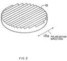
- a feature of this arrangement lies in that the rear mirror 10 ensure the maximum reflectivity of a linear polarization beam E vector having a direction as indicated by an arrow 10a, a detailed description of which will be given later.
- Another feature of this arrangement lies in the folding mirrors 11 and 12, both of which serve as a phase retarder imposing the ⁇ /2 phase delay. Note, although an amount of phase delay of each of the folding mirrors 11 and 12 can be determined as desired, the total amount of phase delay imposed by the two folding mirrors 11 and 12 is ⁇ /2. Such a folding retarder is readily available on the market.
- the laser beam in the region around an optical axis 7a exhibits a linear polarization having the E vector direction as indicated by arrows 10a and 10b, which direction is shifted by ⁇ /4 with respect to the plane defined by the optical axes 7a, 7b and 7c.
- the laser beam In the region around the optical axis 7c, the laser beam exhibits a circular polarization.
- the laser beam oscillation occurs in a composite polarization state within the resonator; that is, the polarization of the laser beam differs depending upon the location of the optical path.
- the linear polarization is selectively exhibited because the reflection loss of the rear mirror 10 is low with respect to the polarization, whereas in the region around the axis 7c, the circular polarization is exhibited because the linear polarization beam is converted to the circular polarization beam by the folding mirrors 11 and 12 serving as the phase retarder.
- the output coupling mirror 4 to be employed should not have any directionality in terms of reflectivity. Such a mirror is readily available, since most of the output coupling mirrors on the market do not have any directionality. Accordingly, the laser beam 13 taken out of the resonator has a circular polarization.
- the oscillation in any polarization state would occur because the loss of oscillation in all of the polarization states is the square, so that the laser beam would have a random polarization. Therefore, the rear mirror 10 having a higher reflectivity in the polarization direction indicated by the arrow 10a must be employed.
- FIG. 2 is a schematic view showing the rear mirror 10, in which the grooves on the surface of the mirror 10 are depicted on an enlarged scale; the actual dimension of each groove is less than 10 ⁇ m, as described later.
- the arrow 10a indicates the preferred polarization direction.
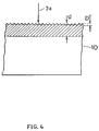
- Figure 3 is a vertical cross-sectional view showing the rear mirror 10, in which the line denoted by 7a indicates an optical axis of a standing-wave within the resonator.
- the light incident perpendicularly upon the overall plane surface of the mirror is obliquely incident upon a face of the groove.
- a reflection of the laser beam results from the oscillation of free electrons confined within the region defined by the skin depth.
- the values of Rv and Rp depend upon n ⁇ and ⁇ .
- d represents a skin depth and D a groove depth.
- the oscillation of free electrons occurs in the region of the skin depth d indicated by oblique lines. Therefore, it is apparent that the undulating surface arrangment on the mirror has no influence on the oscillation of most of the free electrons, wherein the values of Rv and Rp are equal to each other, and as a result, the depth D of the groove has a lower limit D ⁇ d.
- the depth of the undulating pattern on the surface of each optical part must be equal to or greater than the skin depth.
- the skin depth d becomes 6.2 nm (62 ⁇ ).
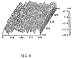
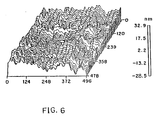
- the surface of such a copper mirror is undulating as shown in Figs. 5 and 6, and thus complies with the requirement as mentioned above.
- Figure 5 is an enlarged perspective view showing a mirror surface of a single crystal copper mirror machined by the diamond lathe
- Fig. 6 is an enlarged perspective view showing a mirror surface of a polycrystal copper mirror machined by the diamond lathe.
- Figs. 5 is an enlarged perspective view showing a mirror surface of a single crystal copper mirror machined by the diamond lathe
- Fig. 6 is an enlarged perspective view showing a mirror surface of a polycrystal copper mirror machined by the diamond lathe.
- a unitary dimension in the X and Y axes is ⁇ m and that in the Z axis is nm.
- the maximum depth in Fig. 5 is about 39.8nm, and the same in Fig. 6 is 61.4nm.
- the mirror surface operates as a diffraction grating.
- the reflection light in this case is diffracted not only to a zero-order term but also to high-order terms. This is not desirable in the present invention, since a substantial part of the reflectivity is lost and thus the output power is lowered.
- the laser beam is oscillated at a high efficiency only when each groove arrangement as shown in Fig. 3 acts precisely as a roof prism.
- the linear polarization can be obtained, and thus a folding mirror configured can be used in the present invention as such. Nevertheless, the following disadvantages arise.
- the regions corresponding to apexes and valleys of the undulating pattern do not contribute to the oscillation, and thus the output power is lower. Consequently, the described mirror surface preferably is not used in the present invention.
- the upper limit of the groove depth D is equal to the laser wavelength. It should be noted that the wavelength of the CO2 laser is 10.6 ⁇ m.
- a parallel engraving line pattern must be formed in one direction on the mirror surface, but the pattern need not be the roof prism arrangement as shown in Fig. 3.
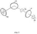
- FIG. 7 shows a rear mirror 10, a folding mirror 11, and an output coupling mirror 4; 13 denotes an output beam (circularly polarized beam).
- Fig. 7 shows a rear mirror 10, a folding mirror 11, and an output coupling mirror 4; 13 denotes an output beam (circularly polarized beam).
- a second embodiment only one folding mirror is employed.
- the basic operational principle of the second embodiment is similar to that of the first embodiment except that, in this second embodiment, the phase delay of ⁇ /2 is imposed by a phase retarder composed of only one folding mirror 11.
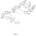
- a third embodiment of the present invention will be described with reference to Fig. 8, which shows a rear mirror 10, folding mirrors 111, 112,...11N, 121, 122,...12N, and an output coupling mirror 4.
- a multi-stage folded resonator comprised of a plurality of folding mirrors is provided, in which the phase delay of ⁇ /2 is imposed by those folding mirrors as a whole.
- the basic operational principle of this embodiment is similar to that of the first and second embodiments.
- the laser oscillator is arranged so that the laser beam irradiated therefrom has a circular polarization, and therefore, it is not necessary to provide specific parts for obtaining the circular polarization beam. Accordingly, in a laser cutting machine for use in metal or non-metal cutting, various advantages are obtained in terms of cost, structure, and properties, etc.
Landscapes
- Physics & Mathematics (AREA)
- Electromagnetism (AREA)
- Engineering & Computer Science (AREA)
- Plasma & Fusion (AREA)
- Optics & Photonics (AREA)
- Lasers (AREA)
- Optical Elements Other Than Lenses (AREA)
Abstract
Claims (5)
- Un oscillateur laser pour faire osciller un faisceau laser, ledit oscillateur comprenant :
un miroir de couplage-sortie (4) ;
au moins un miroir de déviation (11,12) agissant, dans son ensemble, comme un retardateur de phase imposant un retard de phase de π /2 par rapport aux composantes de polarisation parallèle et perpendiculaire dudit faisceau laser : et
un miroir arrière (10) présentant un pouvoir réfléchissant maximum quant à une composante de polarisation linéaire dudit faisceau laser, ladite composante de polarisation linéaire ayant un vecteur E dont la direction (10a, 10b) est tournée de π /4 à partir d'un plan d'incidence du miroir le plus proche desdits miroirs de déviation. - L'oscillateur laser selon la revendication 1, dans lequel ledit miroir arrière présente une surface sur laquelle est formé un réseau de sillons, lesdits sillons étant orientés parallèlement les uns par rapport aux autres dans une direction.
- L'oscillateur laser selon la revendication 2, dans lequel lesdits sillons ont une profondeur entrant dans la gamme sétendant d'une longueur d'onde dudit faisceau laser à une épaisseur de peau sur ledit miroir de couplage ou lesdits miroirs de déviation à une longueur d'onde dudit faisceau laser.
- L'oscillateur laser selon la revendication 2, dans lequel la profondeur desdits sillons entre dans la gamme s'étendant de 6 nm (60Å) à 10 µm.
- L'oscillateur laser selon la revendication 2, dans lequel ledit miroir arrière présente une surface de miroir découpée par usinage avec un tour à diamant.
Applications Claiming Priority (2)
| Application Number | Priority Date | Filing Date | Title |
|---|---|---|---|
| JP2153/88 | 1988-01-08 | ||
| JP63002153A JP2514680B2 (ja) | 1988-01-08 | 1988-01-08 | レ―ザ発振装置 |
Publications (3)
| Publication Number | Publication Date |
|---|---|
| EP0358769A4 EP0358769A4 (fr) | 1990-03-12 |
| EP0358769A1 EP0358769A1 (fr) | 1990-03-21 |
| EP0358769B1 true EP0358769B1 (fr) | 1993-04-21 |
Family
ID=11521410
Family Applications (1)
| Application Number | Title | Priority Date | Filing Date |
|---|---|---|---|
| EP89901304A Expired - Lifetime EP0358769B1 (fr) | 1988-01-08 | 1989-01-06 | Oscillateur laser |
Country Status (4)
| Country | Link |
|---|---|
| US (1) | US4977574A (fr) |
| EP (1) | EP0358769B1 (fr) |
| JP (1) | JP2514680B2 (fr) |
| WO (1) | WO1989006449A1 (fr) |
Families Citing this family (11)
| Publication number | Priority date | Publication date | Assignee | Title |
|---|---|---|---|---|
| JPH01243796A (ja) * | 1988-03-25 | 1989-09-28 | Mitsubishi Electric Corp | 画像符号化伝送装置 |
| JP2651263B2 (ja) * | 1990-06-11 | 1997-09-10 | ファナック株式会社 | レーザ発振装置 |
| JP2872855B2 (ja) * | 1992-02-19 | 1999-03-24 | ファナック株式会社 | レーザ発振器 |
| US5696787A (en) * | 1992-03-30 | 1997-12-09 | Fanuc Ltd. | Laser oscillation apparatus |
| US5283795A (en) * | 1992-04-21 | 1994-02-01 | Hughes Aircraft Company | Diffraction grating driven linear frequency chirped laser |
| JPH06140697A (ja) * | 1992-10-26 | 1994-05-20 | Fanuc Ltd | レーザ発振装置 |
| JPH07211972A (ja) * | 1994-01-20 | 1995-08-11 | Fanuc Ltd | レーザ発振器 |
| US5878067A (en) * | 1994-08-10 | 1999-03-02 | Fanuc Ltd. | Laser oscillator |
| JPH0856028A (ja) * | 1994-08-10 | 1996-02-27 | Fanuc Ltd | レーザ発振器 |
| DE202005006838U1 (de) * | 2005-04-29 | 2006-08-31 | Trumpf Werkzeugmaschinen Gmbh + Co. Kg | Optisches Modul zum Einbau in den Laser einer Laserbearbeitungsmaschine |
| JP6420216B2 (ja) * | 2015-07-31 | 2018-11-07 | ファナック株式会社 | 折返しミラーを備えたレーザ発振器 |
Family Cites Families (7)
| Publication number | Priority date | Publication date | Assignee | Title |
|---|---|---|---|---|
| US3496483A (en) * | 1964-02-28 | 1970-02-17 | Ibm | Laser polarization modulation techniques |
| US4084883A (en) * | 1977-02-28 | 1978-04-18 | The University Of Rochester | Reflective polarization retarder and laser apparatus utilizing same |
| GB2050683B (en) * | 1979-06-02 | 1983-09-14 | Ferranti Ltd | Lasers |
| JPH0624276B2 (ja) * | 1984-01-25 | 1994-03-30 | 株式会社日立製作所 | レ−ザ装置 |
| JPS60211989A (ja) * | 1984-04-06 | 1985-10-24 | Mitsubishi Electric Corp | レ−ザ発振器 |
| JPS60211990A (ja) * | 1984-04-06 | 1985-10-24 | Mitsubishi Electric Corp | レ−ザ発振器 |
| US4757514A (en) * | 1985-08-13 | 1988-07-12 | Laser Corporation Of America | Wire array light polarizer for gas laser |
-
1988
- 1988-01-08 JP JP63002153A patent/JP2514680B2/ja not_active Expired - Fee Related
-
1989
- 1989-01-06 WO PCT/JP1989/000011 patent/WO1989006449A1/fr not_active Ceased
- 1989-01-06 EP EP89901304A patent/EP0358769B1/fr not_active Expired - Lifetime
- 1989-01-06 US US07/408,484 patent/US4977574A/en not_active Expired - Lifetime
Also Published As
| Publication number | Publication date |
|---|---|
| US4977574A (en) | 1990-12-11 |
| EP0358769A4 (fr) | 1990-03-12 |
| JP2514680B2 (ja) | 1996-07-10 |
| EP0358769A1 (fr) | 1990-03-21 |
| JPH01181484A (ja) | 1989-07-19 |
| WO1989006449A1 (fr) | 1989-07-13 |
Similar Documents
| Publication | Publication Date | Title |
|---|---|---|
| US5946337A (en) | Hybrid laser resonator with special line narrowing | |
| EP0358769B1 (fr) | Oscillateur laser | |
| US6763054B2 (en) | Optical system for improving the brightness of a stack of lensed diode lasers | |
| EP0240293B1 (fr) | Source de lumière à fréquence stabilisée | |
| US4972429A (en) | Achromatic prism beam expander for high magnification and tunable laser using same | |
| EP0176812B1 (fr) | Dispositif optique | |
| EP1139523A2 (fr) | Source de lumière pour un laser à cavité externe | |
| CA2116714A1 (fr) | Element optique saturable quasi-monolithique | |
| EP0231050B1 (fr) | Résonateur laser instable muni d'un coupleur de sortie ayant une réflectivité variable radialement | |
| EP0955707B1 (fr) | Système laser | |
| JP2011204943A (ja) | レーザ発振器および反射型回折光学素子 | |
| US20020090017A1 (en) | Device and method for reduction of spontaneous emission from external cavity lasers | |
| US5502738A (en) | Polarization control element and solid-state laser system | |
| EP0623979B1 (fr) | Oscillateur a laser | |
| EP0485619B1 (fr) | Dispositif oscillant a laser | |
| US4559500A (en) | Mirror-grating tuning arrangement for high resolution lasers | |
| JPH01189972A (ja) | レーザ発振装置 | |
| JP2634610B2 (ja) | レーザ発振装置 | |
| US4219786A (en) | Polarization suppression of parasitic modes | |
| JP3069643B2 (ja) | 波長可変光源 | |
| JP2685923B2 (ja) | レーザ共振器 | |
| SU1277271A1 (ru) | Субмиллиметровый лазер | |
| JPH0239872B2 (fr) | ||
| Trebino et al. | A comparison of the Cassegrain and other beam expanders in high-power pulsed dye lasers | |
| EP0489956B1 (fr) | Appareil laser à bande étroite |
Legal Events
| Date | Code | Title | Description |
|---|---|---|---|
| PUAI | Public reference made under article 153(3) epc to a published international application that has entered the european phase |
Free format text: ORIGINAL CODE: 0009012 |
|
| 17P | Request for examination filed |
Effective date: 19890928 |
|
| AK | Designated contracting states |
Kind code of ref document: A1 Designated state(s): DE FR GB |
|
| A4 | Supplementary search report drawn up and despatched |
Effective date: 19900312 |
|
| 17Q | First examination report despatched |
Effective date: 19920630 |
|
| GRAA | (expected) grant |
Free format text: ORIGINAL CODE: 0009210 |
|
| AK | Designated contracting states |
Kind code of ref document: B1 Designated state(s): DE FR GB |
|
| REF | Corresponds to: |
Ref document number: 68906104 Country of ref document: DE Date of ref document: 19930527 |
|
| ET | Fr: translation filed | ||
| PLBE | No opposition filed within time limit |
Free format text: ORIGINAL CODE: 0009261 |
|
| STAA | Information on the status of an ep patent application or granted ep patent |
Free format text: STATUS: NO OPPOSITION FILED WITHIN TIME LIMIT |
|
| 26N | No opposition filed | ||
| PGFP | Annual fee paid to national office [announced via postgrant information from national office to epo] |
Ref country code: FR Payment date: 19980109 Year of fee payment: 10 |
|
| PGFP | Annual fee paid to national office [announced via postgrant information from national office to epo] |
Ref country code: GB Payment date: 19990107 Year of fee payment: 11 |
|
| PG25 | Lapsed in a contracting state [announced via postgrant information from national office to epo] |
Ref country code: FR Free format text: LAPSE BECAUSE OF NON-PAYMENT OF DUE FEES Effective date: 19990930 |
|
| REG | Reference to a national code |
Ref country code: FR Ref legal event code: ST |
|
| PG25 | Lapsed in a contracting state [announced via postgrant information from national office to epo] |
Ref country code: GB Free format text: LAPSE BECAUSE OF NON-PAYMENT OF DUE FEES Effective date: 20000106 |
|
| GBPC | Gb: european patent ceased through non-payment of renewal fee |
Effective date: 20000106 |
|
| PGFP | Annual fee paid to national office [announced via postgrant information from national office to epo] |
Ref country code: DE Payment date: 20060309 Year of fee payment: 18 |
|
| PG25 | Lapsed in a contracting state [announced via postgrant information from national office to epo] |
Ref country code: DE Free format text: LAPSE BECAUSE OF NON-PAYMENT OF DUE FEES Effective date: 20070801 |