EP0358801B1 - Procédé pour la fabrication en continu de matériaux composites à base de titane renforçés par des fibres - Google Patents
Procédé pour la fabrication en continu de matériaux composites à base de titane renforçés par des fibres Download PDFInfo
- Publication number
- EP0358801B1 EP0358801B1 EP88115081A EP88115081A EP0358801B1 EP 0358801 B1 EP0358801 B1 EP 0358801B1 EP 88115081 A EP88115081 A EP 88115081A EP 88115081 A EP88115081 A EP 88115081A EP 0358801 B1 EP0358801 B1 EP 0358801B1
- Authority
- EP
- European Patent Office
- Prior art keywords
- drum
- powder
- plasma
- gun
- titanium base
- Prior art date
- Legal status (The legal status is an assumption and is not a legal conclusion. Google has not performed a legal analysis and makes no representation as to the accuracy of the status listed.)
- Expired - Lifetime
Links
- RTAQQCXQSZGOHL-UHFFFAOYSA-N Titanium Chemical compound [Ti] RTAQQCXQSZGOHL-UHFFFAOYSA-N 0.000 title claims description 51
- 239000010936 titanium Substances 0.000 title claims description 51
- 229910052719 titanium Inorganic materials 0.000 title claims description 51
- 238000000034 method Methods 0.000 title claims description 26
- 238000004519 manufacturing process Methods 0.000 title claims description 7
- 239000000835 fiber Substances 0.000 title description 15
- 239000002131 composite material Substances 0.000 title description 13
- 239000000843 powder Substances 0.000 claims description 40
- 229910045601 alloy Inorganic materials 0.000 claims description 37
- 239000000956 alloy Substances 0.000 claims description 37
- HBMJWWWQQXIZIP-UHFFFAOYSA-N silicon carbide Chemical compound [Si+]#[C-] HBMJWWWQQXIZIP-UHFFFAOYSA-N 0.000 claims description 26
- 229910010271 silicon carbide Inorganic materials 0.000 claims description 26
- 239000011888 foil Substances 0.000 claims description 25
- 238000000151 deposition Methods 0.000 claims description 24
- 230000008021 deposition Effects 0.000 claims description 21
- 239000002245 particle Substances 0.000 claims description 21
- 239000007921 spray Substances 0.000 claims description 21
- ZOKXTWBITQBERF-UHFFFAOYSA-N Molybdenum Chemical compound [Mo] ZOKXTWBITQBERF-UHFFFAOYSA-N 0.000 claims description 14
- 229910052750 molybdenum Inorganic materials 0.000 claims description 12
- 239000011733 molybdenum Substances 0.000 claims description 12
- 229910000883 Ti6Al4V Inorganic materials 0.000 claims description 8
- 239000010953 base metal Substances 0.000 claims description 8
- 239000003870 refractory metal Substances 0.000 claims description 8
- 239000000203 mixture Substances 0.000 claims description 7
- 229910021330 Ti3Al Inorganic materials 0.000 claims description 5
- 229910000765 intermetallic Inorganic materials 0.000 claims description 4
- 229910002065 alloy metal Inorganic materials 0.000 claims description 3
- 239000013078 crystal Substances 0.000 claims description 2
- 239000010955 niobium Substances 0.000 claims 2
- 229910052758 niobium Inorganic materials 0.000 claims 2
- GUCVJGMIXFAOAE-UHFFFAOYSA-N niobium atom Chemical compound [Nb] GUCVJGMIXFAOAE-UHFFFAOYSA-N 0.000 claims 2
- 239000007789 gas Substances 0.000 description 25
- 229910052751 metal Inorganic materials 0.000 description 11
- 239000002184 metal Substances 0.000 description 11
- XKRFYHLGVUSROY-UHFFFAOYSA-N Argon Chemical compound [Ar] XKRFYHLGVUSROY-UHFFFAOYSA-N 0.000 description 10
- 229910001069 Ti alloy Inorganic materials 0.000 description 10
- XLYOFNOQVPJJNP-UHFFFAOYSA-N water Substances O XLYOFNOQVPJJNP-UHFFFAOYSA-N 0.000 description 10
- QVGXLLKOCUKJST-UHFFFAOYSA-N atomic oxygen Chemical compound [O] QVGXLLKOCUKJST-UHFFFAOYSA-N 0.000 description 8
- 239000001301 oxygen Substances 0.000 description 8
- 229910052760 oxygen Inorganic materials 0.000 description 8
- 239000000758 substrate Substances 0.000 description 7
- IJGRMHOSHXDMSA-UHFFFAOYSA-N Atomic nitrogen Chemical compound N#N IJGRMHOSHXDMSA-UHFFFAOYSA-N 0.000 description 6
- PXHVJJICTQNCMI-UHFFFAOYSA-N Nickel Chemical compound [Ni] PXHVJJICTQNCMI-UHFFFAOYSA-N 0.000 description 6
- 229910000831 Steel Inorganic materials 0.000 description 6
- 230000015572 biosynthetic process Effects 0.000 description 6
- 239000010410 layer Substances 0.000 description 6
- 230000008569 process Effects 0.000 description 6
- 239000010959 steel Substances 0.000 description 6
- 229910000601 superalloy Inorganic materials 0.000 description 6
- 229910052786 argon Inorganic materials 0.000 description 5
- 239000012159 carrier gas Substances 0.000 description 5
- 239000000463 material Substances 0.000 description 5
- XEEYBQQBJWHFJM-UHFFFAOYSA-N Iron Chemical compound [Fe] XEEYBQQBJWHFJM-UHFFFAOYSA-N 0.000 description 4
- 229910052782 aluminium Inorganic materials 0.000 description 4
- XAGFODPZIPBFFR-UHFFFAOYSA-N aluminium Chemical compound [Al] XAGFODPZIPBFFR-UHFFFAOYSA-N 0.000 description 4
- 238000000576 coating method Methods 0.000 description 4
- 238000001816 cooling Methods 0.000 description 4
- 239000011159 matrix material Substances 0.000 description 4
- 239000010453 quartz Substances 0.000 description 4
- VYPSYNLAJGMNEJ-UHFFFAOYSA-N silicon dioxide Inorganic materials O=[Si]=O VYPSYNLAJGMNEJ-UHFFFAOYSA-N 0.000 description 4
- OKTJSMMVPCPJKN-UHFFFAOYSA-N Carbon Chemical compound [C] OKTJSMMVPCPJKN-UHFFFAOYSA-N 0.000 description 3
- 230000009471 action Effects 0.000 description 3
- 239000011248 coating agent Substances 0.000 description 3
- 230000007423 decrease Effects 0.000 description 3
- 239000007788 liquid Substances 0.000 description 3
- 229910052759 nickel Inorganic materials 0.000 description 3
- 229910052757 nitrogen Inorganic materials 0.000 description 3
- 238000009877 rendering Methods 0.000 description 3
- 238000005507 spraying Methods 0.000 description 3
- LEONUFNNVUYDNQ-UHFFFAOYSA-N vanadium atom Chemical compound [V] LEONUFNNVUYDNQ-UHFFFAOYSA-N 0.000 description 3
- 229910010038 TiAl Inorganic materials 0.000 description 2
- UQZIWOQVLUASCR-UHFFFAOYSA-N alumane;titanium Chemical compound [AlH3].[Ti] UQZIWOQVLUASCR-UHFFFAOYSA-N 0.000 description 2
- 238000013459 approach Methods 0.000 description 2
- 230000008901 benefit Effects 0.000 description 2
- 229910052799 carbon Inorganic materials 0.000 description 2
- 238000005137 deposition process Methods 0.000 description 2
- 238000007731 hot pressing Methods 0.000 description 2
- 238000002347 injection Methods 0.000 description 2
- 239000007924 injection Substances 0.000 description 2
- 230000003993 interaction Effects 0.000 description 2
- 229910052742 iron Inorganic materials 0.000 description 2
- 238000009718 spray deposition Methods 0.000 description 2
- 229910052720 vanadium Inorganic materials 0.000 description 2
- 238000004804 winding Methods 0.000 description 2
- RYGMFSIKBFXOCR-UHFFFAOYSA-N Copper Chemical compound [Cu] RYGMFSIKBFXOCR-UHFFFAOYSA-N 0.000 description 1
- UFHFLCQGNIYNRP-UHFFFAOYSA-N Hydrogen Chemical compound [H][H] UFHFLCQGNIYNRP-UHFFFAOYSA-N 0.000 description 1
- XUIMIQQOPSSXEZ-UHFFFAOYSA-N Silicon Chemical compound [Si] XUIMIQQOPSSXEZ-UHFFFAOYSA-N 0.000 description 1
- 229910010039 TiAl3 Inorganic materials 0.000 description 1
- OQPDWFJSZHWILH-UHFFFAOYSA-N [Al].[Al].[Al].[Ti] Chemical compound [Al].[Al].[Al].[Ti] OQPDWFJSZHWILH-UHFFFAOYSA-N 0.000 description 1
- 238000010521 absorption reaction Methods 0.000 description 1
- 230000001154 acute effect Effects 0.000 description 1
- 230000001464 adherent effect Effects 0.000 description 1
- 230000003466 anti-cipated effect Effects 0.000 description 1
- 238000006243 chemical reaction Methods 0.000 description 1
- 238000005229 chemical vapour deposition Methods 0.000 description 1
- 239000010941 cobalt Substances 0.000 description 1
- 229910017052 cobalt Inorganic materials 0.000 description 1
- GUTLYIVDDKVIGB-UHFFFAOYSA-N cobalt atom Chemical compound [Co] GUTLYIVDDKVIGB-UHFFFAOYSA-N 0.000 description 1
- 239000000470 constituent Substances 0.000 description 1
- 238000011437 continuous method Methods 0.000 description 1
- 239000000110 cooling liquid Substances 0.000 description 1
- 239000000498 cooling water Substances 0.000 description 1
- 229910052802 copper Inorganic materials 0.000 description 1
- 239000010949 copper Substances 0.000 description 1
- 238000005520 cutting process Methods 0.000 description 1
- 230000000694 effects Effects 0.000 description 1
- 238000005516 engineering process Methods 0.000 description 1
- 238000002474 experimental method Methods 0.000 description 1
- 230000004927 fusion Effects 0.000 description 1
- 239000011521 glass Substances 0.000 description 1
- 238000010438 heat treatment Methods 0.000 description 1
- 239000001307 helium Substances 0.000 description 1
- 229910052734 helium Inorganic materials 0.000 description 1
- SWQJXJOGLNCZEY-UHFFFAOYSA-N helium atom Chemical compound [He] SWQJXJOGLNCZEY-UHFFFAOYSA-N 0.000 description 1
- 239000001257 hydrogen Substances 0.000 description 1
- 150000002431 hydrogen Chemical class 0.000 description 1
- 229910052739 hydrogen Inorganic materials 0.000 description 1
- 238000010348 incorporation Methods 0.000 description 1
- 238000007689 inspection Methods 0.000 description 1
- 230000007246 mechanism Effects 0.000 description 1
- 239000011156 metal matrix composite Substances 0.000 description 1
- 238000012545 processing Methods 0.000 description 1
- 239000002296 pyrolytic carbon Substances 0.000 description 1
- 238000003908 quality control method Methods 0.000 description 1
- 238000007712 rapid solidification Methods 0.000 description 1
- 230000002787 reinforcement Effects 0.000 description 1
- 239000012783 reinforcing fiber Substances 0.000 description 1
- 239000012779 reinforcing material Substances 0.000 description 1
- 238000005096 rolling process Methods 0.000 description 1
- 229910052710 silicon Inorganic materials 0.000 description 1
- 239000010703 silicon Substances 0.000 description 1
- 239000010935 stainless steel Substances 0.000 description 1
- 229910001220 stainless steel Inorganic materials 0.000 description 1
- 239000002344 surface layer Substances 0.000 description 1
- 229910052715 tantalum Inorganic materials 0.000 description 1
- GUVRBAGPIYLISA-UHFFFAOYSA-N tantalum atom Chemical compound [Ta] GUVRBAGPIYLISA-UHFFFAOYSA-N 0.000 description 1
- 239000013077 target material Substances 0.000 description 1
- 229910021324 titanium aluminide Inorganic materials 0.000 description 1
- WFKWXMTUELFFGS-UHFFFAOYSA-N tungsten Chemical compound [W] WFKWXMTUELFFGS-UHFFFAOYSA-N 0.000 description 1
- 229910052721 tungsten Inorganic materials 0.000 description 1
- 239000010937 tungsten Substances 0.000 description 1
- 238000003466 welding Methods 0.000 description 1
Images



Classifications
-
- C—CHEMISTRY; METALLURGY
- C22—METALLURGY; FERROUS OR NON-FERROUS ALLOYS; TREATMENT OF ALLOYS OR NON-FERROUS METALS
- C22C—ALLOYS
- C22C47/00—Making alloys containing metallic or non-metallic fibres or filaments
- C22C47/16—Making alloys containing metallic or non-metallic fibres or filaments by thermal spraying of the metal, e.g. plasma spraying
-
- C—CHEMISTRY; METALLURGY
- C23—COATING METALLIC MATERIAL; COATING MATERIAL WITH METALLIC MATERIAL; CHEMICAL SURFACE TREATMENT; DIFFUSION TREATMENT OF METALLIC MATERIAL; COATING BY VACUUM EVAPORATION, BY SPUTTERING, BY ION IMPLANTATION OR BY CHEMICAL VAPOUR DEPOSITION, IN GENERAL; INHIBITING CORROSION OF METALLIC MATERIAL OR INCRUSTATION IN GENERAL
- C23C—COATING METALLIC MATERIAL; COATING MATERIAL WITH METALLIC MATERIAL; SURFACE TREATMENT OF METALLIC MATERIAL BY DIFFUSION INTO THE SURFACE, BY CHEMICAL CONVERSION OR SUBSTITUTION; COATING BY VACUUM EVAPORATION, BY SPUTTERING, BY ION IMPLANTATION OR BY CHEMICAL VAPOUR DEPOSITION, IN GENERAL
- C23C4/00—Coating by spraying the coating material in the molten state, e.g. by flame, plasma or electric discharge
- C23C4/04—Coating by spraying the coating material in the molten state, e.g. by flame, plasma or electric discharge characterised by the coating material
- C23C4/06—Metallic material
- C23C4/08—Metallic material containing only metal elements
-
- C—CHEMISTRY; METALLURGY
- C23—COATING METALLIC MATERIAL; COATING MATERIAL WITH METALLIC MATERIAL; CHEMICAL SURFACE TREATMENT; DIFFUSION TREATMENT OF METALLIC MATERIAL; COATING BY VACUUM EVAPORATION, BY SPUTTERING, BY ION IMPLANTATION OR BY CHEMICAL VAPOUR DEPOSITION, IN GENERAL; INHIBITING CORROSION OF METALLIC MATERIAL OR INCRUSTATION IN GENERAL
- C23C—COATING METALLIC MATERIAL; COATING MATERIAL WITH METALLIC MATERIAL; SURFACE TREATMENT OF METALLIC MATERIAL BY DIFFUSION INTO THE SURFACE, BY CHEMICAL CONVERSION OR SUBSTITUTION; COATING BY VACUUM EVAPORATION, BY SPUTTERING, BY ION IMPLANTATION OR BY CHEMICAL VAPOUR DEPOSITION, IN GENERAL
- C23C4/00—Coating by spraying the coating material in the molten state, e.g. by flame, plasma or electric discharge
- C23C4/12—Coating by spraying the coating material in the molten state, e.g. by flame, plasma or electric discharge characterised by the method of spraying
- C23C4/137—Spraying in vacuum or in an inert atmosphere
-
- C—CHEMISTRY; METALLURGY
- C23—COATING METALLIC MATERIAL; COATING MATERIAL WITH METALLIC MATERIAL; CHEMICAL SURFACE TREATMENT; DIFFUSION TREATMENT OF METALLIC MATERIAL; COATING BY VACUUM EVAPORATION, BY SPUTTERING, BY ION IMPLANTATION OR BY CHEMICAL VAPOUR DEPOSITION, IN GENERAL; INHIBITING CORROSION OF METALLIC MATERIAL OR INCRUSTATION IN GENERAL
- C23C—COATING METALLIC MATERIAL; COATING MATERIAL WITH METALLIC MATERIAL; SURFACE TREATMENT OF METALLIC MATERIAL BY DIFFUSION INTO THE SURFACE, BY CHEMICAL CONVERSION OR SUBSTITUTION; COATING BY VACUUM EVAPORATION, BY SPUTTERING, BY ION IMPLANTATION OR BY CHEMICAL VAPOUR DEPOSITION, IN GENERAL
- C23C4/00—Coating by spraying the coating material in the molten state, e.g. by flame, plasma or electric discharge
- C23C4/18—After-treatment
- C23C4/185—Separation of the coating from the substrate
Definitions
- the present invention relates to the formation of filament or fiber reinforced titanium-based composite materials. More particularly it relates to the process of formation on a continuous basis of titanium base alloy matrix composites containing silicon carbide filaments or fibers or similar high temperature high strength filaments as a reinforcing material.
- Such materials have been identified as potential materials of high specific strength, that is high strength to weight materials, making them attractive for use in future aircraft engines having a high trust to weight ratios.
- titanium base alloy matrix composites have been fabricated by rolling titanium base ingot to 0,254 mm (0.010 inch) thick sheet and then laying up alternate layers of titanium base alloy sheet with SiC fibers to form a laminate. The laminate is then consolidated by hot pressing or HIPing. The present process is believed to be inadequate for achieving high rates of production in industrial manufacturing. It is also believed to be too expensive for use in high rate production of such laminates.
- titanium base alloy means an alloy composition in which titanium is at least half of the composition in parts by weight when the various alloy constituents are specified in parts by weight as, for example, in percentage by weight.
- a titanium-aluminum intermetallic compound is a titanium base alloy composition in which titanium and aluminum are present in a simple numerical atomic ratio and the titanium and aluminum are distributed in the composition in a crystal form which corresponds approximately to the simple numerical ratio such as 3:1 for Ti3Al, 1:1 for TiAl; and 1:3 for TiAl3.
- Ti3Al compositions have use temperatures of up to about 760°C (1400°F) as compared to the use temperatures of titanium alloys such as Ti-6Al-4V of up to about 538°C (1000°F).
- the use temperatures of TiAl is in the 927-982°C (1700-1800°F) range.
- European patent application No. 88115079.1 (& EP-A-0358 799) describes a method for overcoming many of the difficulties associated with a laminate sheet approach for fabricating titanium base alloy composites, which employs a cylindrical drum and provides a closely spaced winding of silicon carbide fibers on the drum.
- the wound drum is then coated with a layer of titanium base alloy employing a rapid solidification low pressure plasma deposition process and particularly a process employing radio frequency energy for the plasma deposition process.
- the process forms a metal impregnated silicon carbide filament tape which serves as one of several layers for fabrication of a metal matrix composite layup.
- the layup is then consolidated by hot pressing or HIPing.
- EP-A-0358 799 offers a cost and performance benefit relative to the prior art preformed laminate sheet approach.
- the method of plasma forming the integral individual sheets of the copending application is not a continuous method of fabricating fiber containing metal impregnated sheet and for this reason is inferior to the subject process.
- Novel and unique structures are formed by novel methods pursuant to the present invention by plasma spray deposit of titanium base alloys and titanium-aluminum intermetallic compounds employing RF plasma spray apparatus on a continuous basis.
- a superalloy such as a nickel base, cobalt base, or iron base superalloy can be subdivided to relatively small size Particles of -400 mesh (about 37 ⁇ m) or smaller without causing the powder to accumulate a significant surface deposit of oxygen.
- a nickel base superalloy in powder form having particle size of less than -400 mesh will typically have from about 200 to about 400 parts per million of oxygen.
- a powdered titanium alloy having the same particle size will by contrast typically have a ten fold higher concentration of oxygen.
- a powdered titanium alloy of -400 mesh will have between about 2000 and 4000 ppm of oxygen.
- titanium alloy powder of less than -400 mesh size is recognized as being potentially pyrophoric and as requiring special handling to avoid pyrophoric behavior.
- titanium alloys decreases as the concentration of oxygen and of nitrogen which they contain increases. It is accordingly important to keep the oxygen and nitrogen content of titanium base alloys at a minimum.
- Prior art plasma spray technology is based primarily on use of direct current plasma guns. It has been recognized that most plasma spray deposits of the superalloys such as nickel and iron base superalloys have had relatively low ductility and that such deposits when in their as-deposited form can be cracked when bent through a sufficiently acute angle due to the low ductility.
- RF plasma apparatus is capable of spraying powder of much larger particle size than the conventional d.c. plasma apparatus.
- particle sizes at least three times larger in diameter than those conventionally employed in d.c. plasma spray apparatus may be successfully employed in plasma spray practices and that the particle size may be as high as 100 ⁇ m to 250 ⁇ m and larger and as large as 10X as large as the -400 mesh powder previously employed in d.c. plasma spray practice.
- Another object of the invention is to provide a method for formation of titanium aluminide sheet reinforced by silicon carbide fibers on a continuous basis.
- Another object is to provide a method for forming titanium base alloy in thin sheet form and having silicon fiber reinforcement embedded therein.
- Another object is to provide the sheet as described in the previous object on a continuous basis.
- objects of the invention can be achieved by providing a source of multiple strands of silicon carbide filaments, providing means to continuously align and closely space the filaments onto a cooled polished refractory metal drum to form a continuously advancing tape, rotating the drum to pass the tape of aligned and closely spaced filaments on the drum into a low pressure plasma deposition zone, providing a source of titanium base metal in powder form having an average particle size in excess of 100 ⁇ m, supplying the titanium base powder to a low pressure radio frequency plasma deposition gun so as to pass the powder through the gun and into a plasma flame of said gun, aiming the plasma flame from said gun at a portion of said drum in said low pressure plasma deposition zone to continuously deposit said titanium base metal powder in molten form on and among the filaments of the tape of aligned and closely spaced filaments to at least partially envelop fibers of said tape in the titanium base metal, continuously separating the the titanium bearing tape from said drum after it has passed through said plasma deposition zone, and recovering the fiber bearing titanium base
- a low pressure radio frequency (RF) plasma spray deposit apparatus 10 is made up of a tank 12 having two removable end caps 14 and 16 and the associated apparatus as illustrated in Figure 1.
- the tank may have a length of about 1.52 m (5 feet) and a diameter of about 1.52m (5 feet).
- an RF plasma gun into the top of the tank through an opening formed by cutting an opening in the tank wall and welding a collar 18 to the top of tank 12 along seam 20.
- the RF gun introduced into the tank is positioned within a container in the form of an inverted hat.
- the hat has sidewalls 22 and bottom wall 24 and has a rim 28 which seats on the collar 18 to provide a hermetic seal by techniques well known in the art.
- the gun itself 30 is described in greater detail with reference to Figure 2.
- the gun is mounted to the bottom wall 24 of the inverted hat container 26 and is supplied by power; by gas and by powder entrained in a carrier gas.
- An RF power supply 32 delivers power to the gun 30 over lines 34 and 36. Greater details of its operation are given below with reference to Figure 2.
- Gas is supplied to the interior of gun 30 from gas source 40 through gas supply 38.
- Gas supply means 38 is representative of the means for supply of hydrogen gas or helium gas or argon gas or any mixture of gases as may be needed by the conventionally available RF plasma gun such as TAFA Model 66 used in connection with the examples below.
- the specific gases employed depend on the material being plasma sprayed. The specific gases to be used are known in the art.
- powder entrained in a carrier gas is supplied to the plasma gun from a powder supply means 42 through piping 44.
- a low pressure of 0.267 to 0.533 bar (200 to 400 torr) is maintained within the tank 12 by means of a pump 50 operating through valve 48 and line 46 connected to the tank 12.
- a problem of arc striking against wall interiors from the plasma was studied and was overcome by incorporation of a conical metal shield 52 extending down from gun 30 and by use of gas jets 54 disposed around the plasma flame from gun 30.
- Gas is supplied to the jets through the pipe 56 from exterior gas supply means 60.
- the jets are formed by gas flowing through openings drilled through an annular pipe mounted beneath conical shield 52.
- the pipe 58 serves as a manifold for the gas as well as providing the bottom drilled openings from which the gas jets 54 emerge.
- the object illustrated as that to be coated by plasma spray deposit is a drum 62 held by attached-bolt 70 at the end of an arm 64 extending through one end cap 16 of the tank 12.
- the arm 64 is hermetically sealed through the end cap 16 by a bushing 66 which is mounted within the box 68.
- Conventional means are provided in the box 68 for vertical positioning of the bushing 66 before the apparatus is evacuated.
- the rod may be raised or lowered to permit the position of drum 62 or other sample attached at the end of rod 64 to be adjusted to appropriate positions for the coating process to be performed prior to evacuation of tank 12.
- the drum is subject to rotation by imparting a rotary motion to the external portion of rod 64 by conventional means.
- gas supply pipe 38 and powder supply pipe 44 are provided in supply relationship to the elements of gun 30 as they were in Figure 1.
- the gun 30 is provided with a housing, which includes a closed top wall 82, side walls 84 and a lower opening 86 from which the plasma flame extends.
- Powder supply means 44 is a triple wall tube having a hollow innermost center tube for supply of powder and carrier gas.
- the triple wall is made up of a set of three concentric tubes having a cooling liquid, such as water, flowing in cooling relation in the inner and outer passages between the concentric tubes of powder supply means 44.
- the gas is injected by means 38 into the top of the chamber 88 within gun 30 and above the zone in chamber 88 where the plasma is formed.
- the plasma itself is generated by having the radio frequency power impressed on the gas within the chamber 88.
- a suitable frequency range is from 2 to 5 megahertz. The lower end of this range is preferred.
- the RF power is delivered through the lines 34 and 36 to a helical coil built concentric to the sidewalls 84 of the gun 30. Individual strands 80 of the coil are evident in section in Figure 2.
- the RF coil made up of strands 80, is separated from the chamber 88 and plasma 90 by a quartz tube 92 mounted as a liner within the gun 30.
- a water cooled copper liner 94 made up of a ring of water cooled fingers is also provided in gun 30 within quartz tube 92 as it has been found to assist the operation of the gun at higher powers.
- the space between gun walls 84 and quartz tube 92 is flooded with flowing cooling water (the strands 80 of the coil are in water) so that one side of the quartz tube 92 is directly water cooled.
- An exit baffle 96 assists in orienting the flame of the plasma gun 30.
- the plasma 90 is formed within gun 30 and extends from the bottom of the gun downward into heat delivery relation to the target 63 mounted at the end of rod 64 by a bolt 70.
- a gas or combination of gases is passed through supply means 38 into chamber 88 and the pressure of this gas is kept at a low value by the action of vacuum pump 50 operating through valve 48 and pipe 46 on the low pressure plasma deposition apparatus including tank 12.
- a pressure of about 0.333 bar (250 torr) is suitable.
- the tank itself has a length of about five feet and also a diameter of about five feet.
- Radio frequency power is impressed on the strands 80 of the coil to excite the gas passing into the housing through means 38.
- a plasma 90 is generated within the housing of gun 30. The plasma extends out from the housing and heats the surface of rotatable drum 62. The temperature of the plasma is about 10,000 to 12,000°K.
- Powdered particles, entrained in a carrier gas, are introduced into the plasma 90 through tube 44.
- the heat of the plasma 90 is sufficiently high to cause a fusion of the particles as they move through the plasma and are then deposited as liquid droplets on the surface of the drum 62.
- the plasma from the RF gun as described above will fuse particles of relatively large diameter of more than 100 ⁇ m and will cause them to deposit on a receiving surface from essentially a liquid state.
- the vacuum system is operated to maintain a pressure of approximately 0.333 bar (250 torr) in the low pressure plasma deposition chamber within the container 12.
- the drum 62 may be rotated within the evacuated chamber as the plasma is used to melt particles into molten droplets to be deposited on the surfaces thereof.
- the powder feed mechanism 42 is a conventional commercially available device.
- One particular model used in the practice of this invention was a powder feeder manufactured by Plasmadyne, Inc. of California. It is equipped with a canister on top that holds the powder. A wheel at the bottom of the canister rotates to feed powder into a powder feed hose 44. The powder is then carried by the carrier gas from the powder feeder along the hose 44 to the chamber 88 of gun 30.
- the surface itself is preferably heated prior to the deposit.
- the heating may be by means of the heat from the plasma gun itself before any powder is introduced into the gun.
- a plasma spray deposit of titanium base alloy is made on a water cooled refractory metal rotating drum surface and is continuously removed from the drum as the drum rotates away from the plasma flame which delivers the deposit to the drum.
- a typical run might be carried out under the following conditions: A power input of 60 Kilowatts A tank pressure of 0.333 bar(250 torr) Glass flow rates for a TAFA Model 66: Radial, argon 117 liters/min. Swirl, hydrogen 5 liters/min. Swirl, argon 16 liters/min. cold jet argon 106 liters/min.
- Particle Injection Carrier, argon 5 liters/min. Powder, Ti base alloy 210-250 ⁇ m Injection point above nozzle 7.45 cm.
- Deposition Data Target Material Target size Preformed Steel Foil Distance Target Nozzle 29.21 cm (11.5") Preheating Time 10 min. Deposition Time 10 min. Deposition Rate 30 grams/min. Mass Deposition efficiency 90-95%
- Powder of titanium base alloy,Ti-6Al-4V was obtained.
- the powder had been prepared by the plasma rotating electrode powder (PREP) process known in the art.
- PREP plasma rotating electrode powder
- the powder was screened to yield a powder product having a particle size range of 105 to 177 ⁇ m. This corresponds to a mesh of -80 to +140.
- a rotary drum such as 62 of Figures 1 and 2 was prepared for plasma spray deposit.
- the first step was the mounting of a molybdenum foil onto the drum.
- the foil had a thickness of 0.0508 mm (0.002 inches) and was made of molybdenum metal.
- the surface of the drum was then wound as a second step with a continuous silicon carbide filament.
- the silicon carbide filament was prepared as described in one or more of the Avco Corp. U.S. patents 4,068,037; 4,127,659; 4,481,257; 4,315,968; 4,340,636 and 4,415,609.
- the filaments used has an average diameter of about 0.0056 inches.
- the filament is identified as SCS-6 and it was wound to have a spacing of about 130 filaments per inch.
- This type of filament has a 30 ⁇ m diameter carbon case on which silicon carbide is coated by chemical vapor deposition.
- the coating of SiC is 55 ⁇ m thick.
- the outer surface of the SiC coating has two 1.0 to 1.5 ⁇ m thick pyrolytic carbon layers to give the filament an overall or total diameter of about 142 ⁇ m.
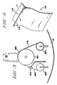
- a photomicrograph of a section through such a filament is shown in Figure 5.
- the carbon core serves as a substrate for the deposition of the SiC which is the structure part of the filament.
- the carbon surface layers are intended to minimize interaction between the SiC and the matrix material of the composite.
- the manufacturer has measured the tensile strength of the filament on the spool as 3150 MPa which is equivalent to 450 ksi. The strength of the filaments was thus somewhat below the values of 3450 to 4140 MPa generally credited to this type of filament.
- a steel bar strap was used to secure the SiC filaments to the drum and to prevent their unwinding from the drum surface as it was subjected to the plasma coating in the apparatus schematically described with regard to Figures 1 and 2.
- Molybdenum foil was employed as the substrate on the drum as it was deemed less reactive with titanium and accordingly it was employed to avoid interactions between the hot Ti-6Al-4V alloy and the exposed metal surface of the drum.
- the silicon carbide filament wound drum was mounted as by the stem 70 and the motion of the drum was controlled by a substrate motion device external to the RF plasma spray facility as explained above.
- the drum was rotated at about 60 revolutions per minute and translated, that is given an axial motion, of about 1 inch per second while being subjected to the plasma spray deposit of the titanium-6 aluminum-4 vanadium powder, i.e. a titanium base alloy containing 6 weight percent aluminum and 4 weight percent vanadium and the balance titanium.
- the substrate drum and foil and closely aligned silicon carbide filaments were not given any preheat prior to the spray deposit of the Ti-6Al-4V alloy powder on the surface thereof through the plasma gun.
- the duration of the spraying was about 3 minutes. Following the 3 minute plasma spray the drum was allowed to cool and was removed from the tank and apparatus.
- the steel strap securing the filaments to the drum surface was removed and the uncoated filaments covered by the strap were cut with an abrasive cutoff wheel.
- Example 1 The procedure of Example 1 was repeated but in this case the foil mounted to the drum was not a molybdenum foil but was rather one made of steel. It was found that the sprayed Ti-6Al-4V alloy adhered to the steel foil as a result of the plasma spray depositing. It was also observed that the alloy of titanium, aluminum and vanadium stuck to the surface of the steel foil where the spraying had been done either with a preheat or without a preheat of the surface on which the deposition was made. This experiment demonstrated that there is a surprisingly and startling difference between the adhesion of a deposit of plasma sprayed metal onto a steel surface as compared to the adhesion of plasma sprayed deposit of essentially the same titanium alloy onto a molybdenum surface.
- Plasma flame 90 may be seen emerging from the lower portion of gun 30 and it will also be seen to be playing on a surface of drum 62.
- Drum 62 has a surface which is formed of one of the refractory metals such as tungsten, tantalum, molybdenum or the like and preferably of molybdenum.
- the drum surface itself is polished and the drum is also internally cooled as by water cooling through conventional means not shown in Figure 3.
- the payout spool 160 is provided with a web or tape 164 of aligned filaments such as silicon carbide filaments. Conventional means, now shown, are provided to permit web 164 to be paid out under tension from spool 160 and to be taken up under tension by a takeup spool 162.
- the tape 164 advances from the payout reel 160 to an alignment and close spacing comb structure and device shown schematically as box 166.
- the tape 164 may be formed either as a preformed tape wound on payout 160 or can be formed by simultaneously feeding multiple spools, not shown, of continuous SiC filament into a comb-like device 166 of Figure 3 to align and closely space the multiple filaments and to form a tape or web which advances onto the surface of drum 62.
- the titanium base alloy metal deposits onto the tape of filaments 164 and in between the filaments onto the surface of the drum 62.
- the plasma spray of the titanium base alloy onto the tape and drum surface causes the formation of a composite structure of titanium base alloy sheet which is impregnated with the SiC fibers.
- the sheet 168 is not adherent to the surface of drum 62 and lifts off as a free standing and independent sheet 170 as it leaves the drum surface and is wound onto the takeup spool 162.
- a continuous foil of unreinforced titanium base metal is formed by continuous deposit of metal from a plasma flame as described above onto a cooled drum surface of polished refractory metal and continuous peeling of the foil as a web from the drum surface.
- Such continuous fabrication of foil may be accomplished with the aid of the schematic apparatus of Figure 3 by depositing the foil continuously on drum 62, continuously peeling the foil from drum 62 and continuously winding the foil onto takeup spool 162.
Landscapes
- Chemical & Material Sciences (AREA)
- Engineering & Computer Science (AREA)
- Physics & Mathematics (AREA)
- Plasma & Fusion (AREA)
- Materials Engineering (AREA)
- Mechanical Engineering (AREA)
- Metallurgy (AREA)
- Organic Chemistry (AREA)
- Chemical Kinetics & Catalysis (AREA)
- Coating By Spraying Or Casting (AREA)
- Manufacture Of Alloys Or Alloy Compounds (AREA)
Claims (9)
- Procédé de fabrication d'une tôle en alliage à base de titane renforcé par des fibres qui comporte :- fournir une source de brins multiples de filaments en carbure de silicium,- fournir un moyen pour aligner en continu et espacer légèrement les filaments sur un tambour poli en métal réfractaire afin de former un ruban qui avance en continu,- faire tourner le tambour pour faire passer le ruban de filaments alignés et légèrement espacés situé sur le tambour dans une région de dépôt par plasma à basse pression,- fournir une source d'alliage métallique à base de titane sous forme de poudre ayant une granulométrie moyenne supérieure à 100 µm,- envoyer la poudre à un canon de dépôt par plasma en radio-fréquence et à basse pression pour qu'elle traverse la flamme plasma dudit canon,- diriger la flamme de plasma provenant dudit canon sur une partie dudit tambour dans ladite région de depôt par plasma en basse pression pour déposer en continu ladite poudre d'alliage métallique à base de titane sous forme fondue sur et entre les filaments du ruban de filaments alignés et légèrement espacés,- séparer en continu le ruban portant l'alliage à base de titane dudit tambour après qu'il a traversé ladite région de dépôt par plasma.
- Procédé selon la revendication 1, dans lequel la granulométrie de la poudre est comprise entre 100 µm et 350 µm.
- Procédé selon la revendication 1, dans lequel l'alliage est Ti-6Al-4V.
- Procédé selon la revendication 1, dans lequel l'alliage est un composé intermétallique Ti₃Al.
- Procédé selon la revendication 1, dans lequel l'alliage est du Ti₃Al modifié par du niobium dans lequel le niobium se substitue au titane dans le réseau cristallin.
- Procédé selon la revendication 5, dans lequel la formule empirique de la composition est Ti-14Al-21Nb.
- Procédé selon la revendication 1, dans lequel le métal réfractaire est du molybdène.
- Procédé de la revenvendication 1, dans lequel la surface de métal réfractaire est refroidie pendant le dépôt par plasma de l'alliage à base de titane.
- Procédé pour produire en continu du métal à base de titane sous forme de feuille qui comporte :- fournir une source de métal à base de titane sous forme de poudre, ladite poudre ayant une granulométrie moyenne supérieure à 100 µm,- fournir un canon de projection de plasma en radio-fréquence,- envoyer ladite poudre audit canon,- déposer par projection de plasma ladite poudre provenant dudit canon sur un tambour refroidi qui tourne comportant une surface en métal réfractaire polie pour former en continu sur celle-ci une feuille autoporteuse, et- décoller en continu ladite feuille autoporteuse dudit tambour pour récupérer ladite feuille.
Priority Applications (1)
| Application Number | Priority Date | Filing Date | Title |
|---|---|---|---|
| DE8888115081T DE3881047D1 (de) | 1987-02-04 | 1988-09-15 | Verfahren zur kontinuierlichen herstellung von faserverstaerkten verbundwerkstoffen auf titanbasis. |
Applications Claiming Priority (1)
| Application Number | Priority Date | Filing Date | Title |
|---|---|---|---|
| US07/010,654 US4782884A (en) | 1987-02-04 | 1987-02-04 | Method for continuous fabrication of fiber reinforced titanium-based composites |
Publications (2)
| Publication Number | Publication Date |
|---|---|
| EP0358801A1 EP0358801A1 (fr) | 1990-03-21 |
| EP0358801B1 true EP0358801B1 (fr) | 1993-05-12 |
Family
ID=21746756
Family Applications (1)
| Application Number | Title | Priority Date | Filing Date |
|---|---|---|---|
| EP88115081A Expired - Lifetime EP0358801B1 (fr) | 1987-02-04 | 1988-09-15 | Procédé pour la fabrication en continu de matériaux composites à base de titane renforçés par des fibres |
Country Status (3)
| Country | Link |
|---|---|
| US (1) | US4782884A (fr) |
| EP (1) | EP0358801B1 (fr) |
| DE (1) | DE3881047D1 (fr) |
Families Citing this family (16)
| Publication number | Priority date | Publication date | Assignee | Title |
|---|---|---|---|---|
| GB8905814D0 (en) * | 1989-03-14 | 1989-04-26 | Rolls Royce Plc | Improvements in or relating to filament coating |
| US4902870A (en) * | 1989-03-31 | 1990-02-20 | General Electric Company | Apparatus and method for transfer arc cleaning of a substrate in an RF plasma system |
| US5229165A (en) * | 1989-11-09 | 1993-07-20 | Allied-Signal Inc. | Plasma sprayed continuously reinforced aluminum base composites |
| US5045407A (en) * | 1989-12-22 | 1991-09-03 | General Electric Company | Silicon carbide fiber-reinforced titanium base composites having improved interface properties |
| US4978585A (en) * | 1990-01-02 | 1990-12-18 | General Electric Company | Silicon carbide fiber-reinforced titanium base composites of improved tensile properties |
| US5074923A (en) * | 1990-03-26 | 1991-12-24 | General Electric Company | Method for id sizing of filament reinforced annular objects |
| US5120567A (en) * | 1990-05-17 | 1992-06-09 | General Electric Company | Low frequency plasma spray method in which a stable plasma is created by operating a spray gun at less than 1 mhz in a mixture of argon and helium gas |
| DE4112745A1 (de) * | 1990-06-29 | 1992-01-02 | Gen Electric | Faserverstaerkter konischer gegenstand und verfahren zu dessen herstellung |
| US5030277A (en) * | 1990-12-17 | 1991-07-09 | The United States Of America As Represented By The Secretary Of The Air Force | Method and titanium aluminide matrix composite |
| US5104460A (en) * | 1990-12-17 | 1992-04-14 | The United States Of America As Represented By The Secretary Of The Air Force | Method to manufacture titanium aluminide matrix composites |
| US5118025A (en) * | 1990-12-17 | 1992-06-02 | The United States Of America As Represented By The Secretary Of The Air Force | Method to fabricate titanium aluminide matrix composites |
| US5240061A (en) * | 1990-12-28 | 1993-08-31 | Osprey Metals Limited | Substrate for spray cast strip |
| US5489411A (en) * | 1991-09-23 | 1996-02-06 | Texas Instruments Incorporated | Titanium metal foils and method of making |
| US5939213A (en) * | 1995-06-06 | 1999-08-17 | Mcdonnell Douglas | Titanium matrix composite laminate |
| US5897922A (en) * | 1997-04-07 | 1999-04-27 | National Research Council Of Canada | Method to manufacture reinforced axi-symmetric metal matrix composite shapes |
| DE10131362A1 (de) | 2001-06-28 | 2003-01-09 | Alstom Switzerland Ltd | Verfahren zur Herstellung einer räumlich geformten, folienartig ausgebildeten Trägerschicht aus sprödhartem Material |
Family Cites Families (7)
| Publication number | Priority date | Publication date | Assignee | Title |
|---|---|---|---|---|
| US3427185A (en) * | 1964-02-19 | 1969-02-11 | United Aircraft Corp | Composite structural material incorporating metallic filaments in a matrix,and method of manufacture |
| US3606667A (en) * | 1968-09-27 | 1971-09-21 | United Aircraft Corp | Method of fabricating fiber-reinforced articles |
| FR2337040A1 (fr) * | 1975-12-31 | 1977-07-29 | Poudres & Explosifs Ste Nale | Perfectionnements aux panneaux metalliques monocouches a fibres a hautes proprietes mecaniques et a leurs procedes de fabrication |
| JPS5774115A (en) * | 1980-10-27 | 1982-05-10 | Res Dev Corp Of Japan | Manufacture of prepreg sheet |
| US4574451A (en) * | 1982-12-22 | 1986-03-11 | General Electric Company | Method for producing an article with a fluid passage |
| JPS60184652A (ja) * | 1984-02-29 | 1985-09-20 | Nikkiso Co Ltd | 繊維強化金属の製造方法 |
| US4576828A (en) * | 1984-05-17 | 1986-03-18 | Geotel, Inc. | Method and apparatus for plasma spray coating |
-
1987
- 1987-02-04 US US07/010,654 patent/US4782884A/en not_active Expired - Fee Related
-
1988
- 1988-09-15 DE DE8888115081T patent/DE3881047D1/de not_active Expired - Lifetime
- 1988-09-15 EP EP88115081A patent/EP0358801B1/fr not_active Expired - Lifetime
Also Published As
| Publication number | Publication date |
|---|---|
| US4782884A (en) | 1988-11-08 |
| EP0358801A1 (fr) | 1990-03-21 |
| DE3881047D1 (de) | 1993-06-17 |
Similar Documents
| Publication | Publication Date | Title |
|---|---|---|
| EP0358799B1 (fr) | Matériaux composites d'aluminiure de titane renforcés par du carbure de silicium | |
| US4782884A (en) | Method for continuous fabrication of fiber reinforced titanium-based composites | |
| US4775547A (en) | RF plasma method of forming multilayer reinforced composites | |
| US12278017B2 (en) | Silicon carbide reinforced zirconium based cladding | |
| US5147448A (en) | Techniques for producing fine metal powder | |
| US5070228A (en) | Method for plasma spray joining active metal substrates | |
| EP0358800B1 (fr) | Procédé de finition de la surface de feuilles d'alliages de titane obtenus par projection au plasma | |
| US4805833A (en) | Method of forming compacts with integral consolidation containers | |
| EP0358802B1 (fr) | Procédé pour la fabrication d'alliages de titane sous forme de feuilles minces | |
| US20050150759A1 (en) | Powder and coating formation method and apparatus | |
| JPH10204601A (ja) | 炭素基材または炭素含有非金属基材を被覆する方法 | |
| US5897922A (en) | Method to manufacture reinforced axi-symmetric metal matrix composite shapes | |
| JPH0770668A (ja) | 金属マトリックス複合材料 | |
| WO2022071823A1 (fr) | Poudre métallique revêtue de carbure sphérique et procédé de production associé | |
| US4941928A (en) | Method of fabricating shaped brittle intermetallic compounds | |
| US5014768A (en) | Chill plate having high heat conductivity and wear resistance | |
| JPH0288732A (ja) | 繊維強化チタン基合金複合材の連続製造方法 | |
| EP0358803A1 (fr) | Procédé pour la fabrication de structures avec enveloppes à raidissement intégral | |
| JP2783813B2 (ja) | 繊維強化金属マトリックス材料の製造方法及び複合構造体 | |
| JP2783814B2 (ja) | Rfプラズマ溶射による多層強化複合体の製造方法 | |
| JPH0288755A (ja) | 箔状チタン合金の製造方法 | |
| JPH0429725B2 (fr) | ||
| JPH0288703A (ja) | プラズマ溶射チタン合金箔の表面仕上げ方法 | |
| Ravisankar et al. | Micro-/nanothick coatings in micro-/nanofabrication | |
| JPH0288702A (ja) | 一体の圧密化用包囲体を有するコンパクトの製造方法 |
Legal Events
| Date | Code | Title | Description |
|---|---|---|---|
| PUAI | Public reference made under article 153(3) epc to a published international application that has entered the european phase |
Free format text: ORIGINAL CODE: 0009012 |
|
| AK | Designated contracting states |
Kind code of ref document: A1 Designated state(s): DE FR GB GR IT NL SE |
|
| 17P | Request for examination filed |
Effective date: 19900817 |
|
| 17Q | First examination report despatched |
Effective date: 19920413 |
|
| GRAA | (expected) grant |
Free format text: ORIGINAL CODE: 0009210 |
|
| AK | Designated contracting states |
Kind code of ref document: B1 Designated state(s): DE FR GB GR IT NL SE |
|
| PG25 | Lapsed in a contracting state [announced via postgrant information from national office to epo] |
Ref country code: NL Effective date: 19930512 Ref country code: FR Free format text: THE PATENT HAS BEEN ANNULLED BY A DECISION OF A NATIONAL AUTHORITY Effective date: 19930512 Ref country code: DE Effective date: 19930512 Ref country code: GR Free format text: LAPSE BECAUSE OF FAILURE TO SUBMIT A TRANSLATION OF THE DESCRIPTION OR TO PAY THE FEE WITHIN THE PRESCRIBED TIME-LIMIT Effective date: 19930512 Ref country code: SE Effective date: 19930512 Ref country code: IT Free format text: LAPSE BECAUSE OF FAILURE TO SUBMIT A TRANSLATION OF THE DESCRIPTION OR TO PAY THE FEE WITHIN THE PRESCRIBED TIME-LIMIT;WARNING: LAPSES OF ITALIAN PATENTS WITH EFFECTIVE DATE BEFORE 2007 MAY HAVE OCCURRED AT ANY TIME BEFORE 2007. THE CORRECT EFFECTIVE DATE MAY BE DIFFERENT FROM THE ONE RECORDED. Effective date: 19930512 |
|
| REF | Corresponds to: |
Ref document number: 3881047 Country of ref document: DE Date of ref document: 19930617 |
|
| ET | Fr: translation filed | ||
| PG25 | Lapsed in a contracting state [announced via postgrant information from national office to epo] |
Ref country code: GB Effective date: 19930915 |
|
| NLV1 | Nl: lapsed or annulled due to failure to fulfill the requirements of art. 29p and 29m of the patents act | ||
| GBPC | Gb: european patent ceased through non-payment of renewal fee |
Effective date: 19930915 |
|
| REG | Reference to a national code |
Ref country code: FR Ref legal event code: ST |
|
| EUG | Se: european patent has lapsed |
Ref document number: 88115081.7 Effective date: 19930624 |
|
| PLBE | No opposition filed within time limit |
Free format text: ORIGINAL CODE: 0009261 |
|
| STAA | Information on the status of an ep patent application or granted ep patent |
Free format text: STATUS: NO OPPOSITION FILED WITHIN TIME LIMIT |