EP0358826A1 - Commande de soupape de moteur à combustion interne - Google Patents
Commande de soupape de moteur à combustion interne Download PDFInfo
- Publication number
- EP0358826A1 EP0358826A1 EP88308609A EP88308609A EP0358826A1 EP 0358826 A1 EP0358826 A1 EP 0358826A1 EP 88308609 A EP88308609 A EP 88308609A EP 88308609 A EP88308609 A EP 88308609A EP 0358826 A1 EP0358826 A1 EP 0358826A1
- Authority
- EP
- European Patent Office
- Prior art keywords
- follower
- valve
- cam
- axis
- track
- Prior art date
- Legal status (The legal status is an assumption and is not a legal conclusion. Google has not performed a legal analysis and makes no representation as to the accuracy of the status listed.)
- Withdrawn
Links
- 238000002485 combustion reaction Methods 0.000 title claims abstract description 6
- 230000008878 coupling Effects 0.000 claims description 4
- 238000010168 coupling process Methods 0.000 claims description 4
- 238000005859 coupling reaction Methods 0.000 claims description 4
- 230000000452 restraining effect Effects 0.000 claims description 2
- 239000000463 material Substances 0.000 description 3
- MCMNRKCIXSYSNV-UHFFFAOYSA-N Zirconium dioxide Chemical compound O=[Zr]=O MCMNRKCIXSYSNV-UHFFFAOYSA-N 0.000 description 2
- 238000000034 method Methods 0.000 description 2
- 229910010293 ceramic material Inorganic materials 0.000 description 1
- 230000002452 interceptive effect Effects 0.000 description 1
- 239000002184 metal Substances 0.000 description 1
- 239000007769 metal material Substances 0.000 description 1
- 229920003023 plastic Polymers 0.000 description 1
- 239000004033 plastic Substances 0.000 description 1
- 239000011435 rock Substances 0.000 description 1
- 238000000926 separation method Methods 0.000 description 1
Images

Classifications
-
- F—MECHANICAL ENGINEERING; LIGHTING; HEATING; WEAPONS; BLASTING
- F01—MACHINES OR ENGINES IN GENERAL; ENGINE PLANTS IN GENERAL; STEAM ENGINES
- F01L—CYCLICALLY OPERATING VALVES FOR MACHINES OR ENGINES
- F01L1/00—Valve-gear or valve arrangements, e.g. lift-valve gear
- F01L1/30—Valve-gear or valve arrangements, e.g. lift-valve gear characterised by the provision of positively opened and closed valves, i.e. desmodromic valves
Definitions
- the present invention relates to an internal combustion engine having one or more reciprocating valves. It is common to provide springs for urging such valves to the closed position and to provide a cam mechanism for opening the valves.
- springs for urging such valves to the closed position
- cam mechanism for opening the valves.
- a relatively large space must be provided in the engine to accommodate the rockers of the Gardner arrangement. This limits the choice in the disposition of other parts of the engine, for example in the routing of inlet ducts and exhaust ducts. Each rocker inevitably possesses considerable mass and so quite large forces have to be exerted to overcome the inertia of the rocker.
- a further disadvantage of the Gardner arrangement is that the motion of the rocker relative to the camshaft axis is along an arcuate path centered on the pivot axis. The rocker executes angular motion relative to the corresponding valve.
- an internal combustion engine having at least one valve which is guided for reciprocation along a rectilinear path, operating means for moving the valve in opposite directions along the path, the operating means comprising a follower, guide means for guiding the follower for reciprocation along a rectilinear path which is an extension of the path along which the valve reciprocates, coupling means for coupling the follower with the valve, a non-circular, endless track formed in the follower and facing towards an axis (called herein the cam axis), which axis is transverse to the path of the follower and a cam supported for rotation around said axis and having a plurality of contact portions which run on the track and cause reciprocation of the follower relative to the cam axis when the cam rotates around the cam axis, the guide means restraining rotation of the follower around the cam axis.
- Operating means in accordance with the present invention can be arranged to occupy a smaller space in the engine than is required to accommodate the Gardner arrangement. Furthermore, the components can be less massive than are components of the Gardner arrangement.
- the follower of operating means in accordance with the present invention reciprocates along a rectilinear path relative to the cam axis so that the position of the follower relative to the cam changes in a relatively simple manner.
- the cam has two only contact portions, these lie at opposite sides of the cam axis
- the track formed in the follower includes two opposite portions which substantially define respective arcs of a common circle and these portions are engaged by respective ones of the contact portions of the cam when the valve is held by the cam and follower in a closed position.
- the camshaft rotates at one quarter crankshaft speed in order that the valves will be opened and closed at the correct times.
- the invention may be applied to an engine arranged generally as disclosed in GB 2,134,977A. That published specification discloses an engine with a number of valves each having a longitudinal axis which intersects a camshaft of the engine and there is interposed between the valve and the camshaft a reciprocating tappet which transmits an opening force from the cam to the valve. For closing the valves, there is associated with each valve a respective spring.
- the engine illustrated in the accompanying drawings differs from that disclosed in GB 2134977 primarily in respect of the operating means provided for opening and closing the valves.
- Figure 1 of the accompanying drawings there is shown a part of a cylinder block defining a cylinder 11 in which a piston 12 reciprocates.
- Figure 1 also shows a part of a cylinder head 13 which defines an inlet duct 14 communicating with the cylinder 11 at an inlet port and an exhaust duct 15 communicating with the cylinder at an exhaust port.
- An inlet valve 16 is provided for closing the inlet port and an exhaust valve 17 is provided for closing the exhaust port.
- the inlet port preferably lies in a plane which is inclined to the exhaust port, the face of the cylinder head which is presented towards the cylinder 11 being of inverted pentroof form.
- the cylinder head supports a camshaft 18 for rotation about a cam axis 19 which is perpendicular to the longitudinal axis of the cylinder 11.
- the axis of the cylinder may intersect the axis 19 or pass near to that axis.
- the inlet valve 16 comprises an elongated, rectilinear stem 20 and a head 21 at one end of the stem which, when the valve is closed, engages a seat defined by the cylinder head 13.
- the stem 20 of the valve is slidably mounted in a valve guide 22 which is fixed in the cylinder head 13 and which guides the valve for reciprocation along a rectilinear path between open and closed positions of the valve. This path is so inclined to the longitudinal axis of the cylinder 11 that a longitudinal axis of the valve stem 20 intersects the cam axis 19 at right angles.
- a further valve guide 23 is mounted in the cylinder head 13 for guiding the exhaust valve 17 for reciprocation along a rectilinear path which is so inclined to the axis of the cylinder that a longitudinal axis of the stem 24 of the exhaust valve also intersects the cam axis 19 substantially at right angles.
- the valve guides 22 and 23 are so positioned that the respective positions where the axes of the valve stems intersect the cam axis 19 are spaced somewhat along the cam axis.
- the inlet valve 16 There is provided for the inlet valve 16 a follower 25 which is disposed adjacent to the end of the valve stem remote from the valve head.
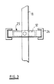
- a guide 26 for guiding the follower 25 for reciprocation along a rectilinear path which is an extension of the path along which the inlet valve 16 moves.
- the guide 26 comprises a pair of opposed, rectilinear and mutually parallel guideways in which respective marginal portions of the follower are received. These marginal portions present in respective opposite directions flat surfaces which have a substantial length in a direction along the associated valve stem and co-operate with the guide 26 to restrain turning of the follower about the cam axis 9.
- the follower 25 is coupled with the inlet valve 16 in a known manner to restrain longitudinal movement of the valve relative to the follower.
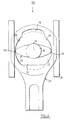
- the follower 25 defines an aperture 27 through which the cam axis 19 extends.
- the internal surface of the follower, which faces towards this axis, constitutes an endless track which is of non-circular form.
- Diammetrically opposed parts 28 and 29 define respective arcs of a circle which, in the closed position of the inlet valve, is centered on the cam axis 19.
- the track parts 28 and 29 are spaced from each other in a direction transverse to the direction in which the follower reciprocates. Between the portions 28 and 29, there lie opposed non-circular track portions 30 and 31.
- the track portion 31 lies nearer to the centre of curvature of the track parts 28 and 29 than are these track parts.
- the track portion 30 lies further from the centre of curvature than are the track parts 28 and 29.
- the separation between the track portions 30 and 31, measured along a line which passes through the centre of curvature of the track parts 28 and 29, is substantially equal to twice the radius of curvature of the track parts 28 and 29.
- a cam 32 having two contact portions, 33 and 34, at diammetrically opposite positions with respect to the cam axis 19.
- the extremeties of the contact portions 33 and 34 are each spaced from the axis 19 by a distance substantially equal to the radius of curvature of the track parts 28 and 29. Accordingly, contact portions 33 and 34 bear, at diammetrically opposite positions, on the track defined by the follower 25.
- the contact portions 33 and 34 may be integral one with the other and engage in sliding contact with the cam track.
- the contact portions may be constituted by rollers which roll on the cam track. It will be understood that small clearances are provided so that one contact element may be just clear of the cam track when the other contact element is in firm contact with the cam track. Furthermore, there is sufficient clearance for the closing of the valve 16 to be completed by pressure within the combustion chamber acting on the head of the valve, without the cam 32 interfering with such movement of the valve. This ensures that the cam 32 does not prevent complete closing of the valve. It will be noted that, when the valve is closed, the contact portions 33 and 34 are engaged with the arcuate portions 28 and 29 of the track.
- valve 16 When the cam 32 turns sufficiently to bring one of the contact portions 33, 34 into engagement with the portion 30 of the track and the other contact portion into engagement with the portion 31 of the track, the valve 16 is moved in a direction away from the cam axis 19 to lift the valve head off its seat and open the valve. As the cam is rotated further to move the contact portions off the track portions 30 and 31, the follower 25 is driven in a direction away from the cylinder 11 to move the valve to the closed position. It will be noted that no valve springs are provided and that the valve is moved positively in both the opening and closing directions.
- the cam 32 and follower 25 have a small extent in a direction along the cam axis 19, for example dimensions in this direction within the range 4 to 8 millimetre.
- the follower may be formed entirely of metal or at least partly of a suitable plastics material, a suitable ceramic material or other non-metallic material, for example toughened zirconia.
- the follower may have a lining of relatively hard material which presents the cam track and a body of other material. Where a number of similar followers are provided in the engine, these may have substantially identical bodies but linings of somewhat different shape, which provide different opening and closing times for different valves.
- a follower 35 which may be identical with or similar to the follower 25, is associated with the exhaust valve 17 and a cam 36, which may be identical with the cam 32, is provided for reciprocating the follower 35. These parts operate in the manner hereinbefore described with reference to the follower 25 and cam 32.
- the operating means for the valves 16 and 17 is compact and enables the inlet duct 14 and the exhaust duct 15 to be routed near to the cam axis 19 so that these ducts are inclined at only small angles to the longitudinal axis of the cylinder 11.
- the followers 25 and 35 can have a low mass, as compared with the mass of rockers.
- the contact portions 33 and 34 are identical and each is symmetrical about a plane which contains the cam axis 19.
- the contact portions may be asymmetrical about such a plane, being provided each with a leading edge which is of somewhat different form than is the trailing edge of the contact portions.
Landscapes
- Engineering & Computer Science (AREA)
- Mechanical Engineering (AREA)
- General Engineering & Computer Science (AREA)
- Valve-Gear Or Valve Arrangements (AREA)
Applications Claiming Priority (1)
| Application Number | Priority Date | Filing Date | Title |
|---|---|---|---|
| GB8706409A GB2202273B (en) | 1987-03-18 | 1987-03-18 | Internal combustion engine |
Publications (1)
| Publication Number | Publication Date |
|---|---|
| EP0358826A1 true EP0358826A1 (fr) | 1990-03-21 |
Family
ID=10614155
Family Applications (1)
| Application Number | Title | Priority Date | Filing Date |
|---|---|---|---|
| EP88308609A Withdrawn EP0358826A1 (fr) | 1987-03-18 | 1988-09-16 | Commande de soupape de moteur à combustion interne |
Country Status (3)
| Country | Link |
|---|---|
| US (1) | US4887565A (fr) |
| EP (1) | EP0358826A1 (fr) |
| GB (1) | GB2202273B (fr) |
Cited By (2)
| Publication number | Priority date | Publication date | Assignee | Title |
|---|---|---|---|---|
| EP0560701A1 (fr) * | 1992-03-13 | 1993-09-15 | MATESIC, Alex | Moteur à combustion interne, avec taux de compression et masse tournante du volant moteur ajustables en marche |
| CN103299036A (zh) * | 2010-12-22 | 2013-09-11 | J·T·多尔蒂 | 无摇杆连控轨道阀系统 |
Families Citing this family (8)
| Publication number | Priority date | Publication date | Assignee | Title |
|---|---|---|---|---|
| JPH03168307A (ja) * | 1989-11-24 | 1991-07-22 | Takuya Matsumoto | エンジンのバルブ駆動装置 |
| IT1280571B1 (it) * | 1995-11-20 | 1998-01-22 | Luca Lucarini | Sistema di trasmissione del moto dalla punteria alla valvola in una distribuzione per un motore endotermico |
| GB2332710A (en) * | 1997-11-03 | 1999-06-30 | Craig Anthony Gager | A desmodromic gas exchange valve actuation arrangement |
| US6053134A (en) * | 1998-08-28 | 2000-04-25 | Linebarger; Terry Glyn | Cam operating system |
| EP1415069A1 (fr) * | 2001-08-06 | 2004-05-06 | Stefan Battlogg | Dispositif pour transformer un mouvement de rotation en un mouvement alternatif |
| US8033261B1 (en) | 2008-11-03 | 2011-10-11 | Robbins Warren H | Valve actuation system and related methods |
| US9366158B1 (en) | 2010-12-22 | 2016-06-14 | James T. Dougherty | Unitary cam follower and valve preload spring for a desmodromic valve mechanism |
| WO2014068365A1 (fr) * | 2012-10-30 | 2014-05-08 | Gualtieri Andrea | Système de distribution amélioré, en particulier du type desmodromique |
Citations (3)
| Publication number | Priority date | Publication date | Assignee | Title |
|---|---|---|---|---|
| FR624260A (fr) * | 1926-03-01 | 1927-07-12 | Commande desmodromique pour moteurs à explosion | |
| GB2166799A (en) * | 1984-11-13 | 1986-05-14 | Bothwell P W | I.c. engine overhead valve gear |
| EP0240446A2 (fr) * | 1986-04-02 | 1987-10-07 | Julian Piedrafita Martin | Arbre à cames |
Family Cites Families (6)
| Publication number | Priority date | Publication date | Assignee | Title |
|---|---|---|---|---|
| US1493419A (en) * | 1920-01-13 | 1924-05-06 | Dorsey F Asbury | Valve mechanism for internal-combustion engines |
| US1937152A (en) * | 1930-12-23 | 1933-11-28 | Junk Walter | Positive valve control for internal combustion engines |
| GB783803A (en) * | 1955-04-20 | 1957-10-02 | Frederick Edward Ellis | Improvements in or relating to internal combustion engines |
| GB1125263A (en) * | 1966-04-26 | 1968-08-28 | Roger Eastham | Improvements in or relating to valve gear for internal combustion engines |
| US4036185A (en) * | 1976-04-09 | 1977-07-19 | Key Edward H | Energy-efficient valve gear |
| US4711202A (en) * | 1986-10-30 | 1987-12-08 | General Motors Corporation | Direct acting cam-valve assembly |
-
1987
- 1987-03-18 GB GB8706409A patent/GB2202273B/en not_active Expired - Lifetime
-
1988
- 1988-09-16 EP EP88308609A patent/EP0358826A1/fr not_active Withdrawn
- 1988-10-27 US US07/263,276 patent/US4887565A/en not_active Expired - Fee Related
Patent Citations (3)
| Publication number | Priority date | Publication date | Assignee | Title |
|---|---|---|---|---|
| FR624260A (fr) * | 1926-03-01 | 1927-07-12 | Commande desmodromique pour moteurs à explosion | |
| GB2166799A (en) * | 1984-11-13 | 1986-05-14 | Bothwell P W | I.c. engine overhead valve gear |
| EP0240446A2 (fr) * | 1986-04-02 | 1987-10-07 | Julian Piedrafita Martin | Arbre à cames |
Non-Patent Citations (1)
| Title |
|---|
| MOTORRAD, vol. 16, July 1985, pages 1-4, Stuttgart, DE; W. SCHNEPF: "Desmodromische Ventilsteuerungen" * |
Cited By (4)
| Publication number | Priority date | Publication date | Assignee | Title |
|---|---|---|---|---|
| EP0560701A1 (fr) * | 1992-03-13 | 1993-09-15 | MATESIC, Alex | Moteur à combustion interne, avec taux de compression et masse tournante du volant moteur ajustables en marche |
| FR2688544A1 (fr) * | 1992-03-13 | 1993-09-17 | Matesic Alex | Moteur a combustion interne a hautes performances avec taux de compression et masse tournante du volant moteur ajustables en marche. |
| CN103299036A (zh) * | 2010-12-22 | 2013-09-11 | J·T·多尔蒂 | 无摇杆连控轨道阀系统 |
| CN103299036B (zh) * | 2010-12-22 | 2016-08-17 | J·T·多尔蒂 | 无摇杆连控轨道阀系统 |
Also Published As
| Publication number | Publication date |
|---|---|
| GB2202273B (en) | 1991-04-17 |
| US4887565A (en) | 1989-12-19 |
| GB2202273A (en) | 1988-09-21 |
| GB8706409D0 (en) | 1987-04-23 |
Similar Documents
| Publication | Publication Date | Title |
|---|---|---|
| US5373818A (en) | Valve gear assembly for an internal-combustion engine | |
| US5606942A (en) | Valve operating system for multi-valve engine | |
| US4469056A (en) | Dual follower variable valve timing mechanism | |
| US7603973B2 (en) | Variable mechanical valve control for an internal combustion engine | |
| US6422187B2 (en) | Variable valve mechanism having an eccentric-driven frame | |
| US5359970A (en) | Valve drive for an internal combustion engine | |
| US5431132A (en) | Variable valve gear of internal combustion engines | |
| JPH07509768A (ja) | エンジンバルブ可変制御方法及び装置 | |
| US4503818A (en) | Variable valve timing arrangement for an internal combustion engine or the like | |
| EP0601570B1 (fr) | Commande de soupape pour moteur à combustion interne | |
| US4887565A (en) | Internal combustion engine | |
| US6295958B2 (en) | Linkless variable valve actuation mechanism | |
| US6386161B2 (en) | Cam link variable valve mechanism | |
| US4858573A (en) | Internal combustion engines | |
| US4476822A (en) | Hypocyclic rolling contact rocker arm and pivot | |
| EP0428691B1 (fr) | Culasses pour des moteurs a combustion interne | |
| US6481397B2 (en) | Variable valve drive system for an internal combustion engine | |
| EP0434331A1 (fr) | Dispositif d'entraînement de soupapes pour moteur à combustion interne | |
| EP0117678A1 (fr) | Mécanisme de soupapes | |
| EP0129961B1 (fr) | Moteur à combustion interne à piston avec un dispositif d'entraînement de soupapes | |
| EP0838576A1 (fr) | Commande de soupapes variable pour moteur à combustion interne | |
| EP1697619B1 (fr) | Commande de soupapes variable | |
| JPH10196333A (ja) | バルブリフタ構造 | |
| GB2166799A (en) | I.c. engine overhead valve gear | |
| EP0444562A1 (fr) | Système de distribution, notamment pour un moteur à combustion interne avec un certain nombre de soupapes par cylindre |
Legal Events
| Date | Code | Title | Description |
|---|---|---|---|
| PUAI | Public reference made under article 153(3) epc to a published international application that has entered the european phase |
Free format text: ORIGINAL CODE: 0009012 |
|
| AK | Designated contracting states |
Kind code of ref document: A1 Designated state(s): AT DE ES FR IT NL SE |
|
| 17P | Request for examination filed |
Effective date: 19900920 |
|
| 17Q | First examination report despatched |
Effective date: 19910503 |
|
| STAA | Information on the status of an ep patent application or granted ep patent |
Free format text: STATUS: THE APPLICATION IS DEEMED TO BE WITHDRAWN |
|
| 18D | Application deemed to be withdrawn |
Effective date: 19940929 |
|
| APAF | Appeal reference modified |
Free format text: ORIGINAL CODE: EPIDOSCREFNE |