EP0359022A1 - Charnière pour portes d'armoires - Google Patents
Charnière pour portes d'armoires Download PDFInfo
- Publication number
- EP0359022A1 EP0359022A1 EP89115886A EP89115886A EP0359022A1 EP 0359022 A1 EP0359022 A1 EP 0359022A1 EP 89115886 A EP89115886 A EP 89115886A EP 89115886 A EP89115886 A EP 89115886A EP 0359022 A1 EP0359022 A1 EP 0359022A1
- Authority
- EP
- European Patent Office
- Prior art keywords
- support arm
- pot
- hinge
- functional element
- hinge according
- Prior art date
- Legal status (The legal status is an assumption and is not a legal conclusion. Google has not performed a legal analysis and makes no representation as to the accuracy of the status listed.)
- Withdrawn
Links
- 230000000295 complement effect Effects 0.000 description 2
- 238000004519 manufacturing process Methods 0.000 description 2
- 238000006073 displacement reaction Methods 0.000 description 1
- 238000003780 insertion Methods 0.000 description 1
- 230000037431 insertion Effects 0.000 description 1
Images



Classifications
-
- E—FIXED CONSTRUCTIONS
- E05—LOCKS; KEYS; WINDOW OR DOOR FITTINGS; SAFES
- E05D—HINGES OR SUSPENSION DEVICES FOR DOORS, WINDOWS OR WINGS
- E05D5/00—Construction of single parts, e.g. the parts for attachment
- E05D5/02—Parts for attachment, e.g. flaps
- E05D5/0276—Parts for attachment, e.g. flaps for attachment to cabinets or furniture, the hinge having two or more pins
-
- E—FIXED CONSTRUCTIONS
- E05—LOCKS; KEYS; WINDOW OR DOOR FITTINGS; SAFES
- E05D—HINGES OR SUSPENSION DEVICES FOR DOORS, WINDOWS OR WINGS
- E05D7/00—Hinges or pivots of special construction
- E05D7/04—Hinges adjustable relative to the wing or the frame
- E05D7/0407—Hinges adjustable relative to the wing or the frame the hinges having two or more pins and being specially adapted for cabinets or furniture
-
- E—FIXED CONSTRUCTIONS
- E05—LOCKS; KEYS; WINDOW OR DOOR FITTINGS; SAFES
- E05Y—INDEXING SCHEME ASSOCIATED WITH SUBCLASSES E05D AND E05F, RELATING TO CONSTRUCTION ELEMENTS, ELECTRIC CONTROL, POWER SUPPLY, POWER SIGNAL OR TRANSMISSION, USER INTERFACES, MOUNTING OR COUPLING, DETAILS, ACCESSORIES, AUXILIARY OPERATIONS NOT OTHERWISE PROVIDED FOR, APPLICATION THEREOF
- E05Y2900/00—Application of doors, windows, wings or fittings thereof
- E05Y2900/20—Application of doors, windows, wings or fittings thereof for furniture, e.g. cabinets
Definitions
- the invention relates to a hinge for cabinet doors or the like, with a base element which can be fastened to a wall of the cabinet and a support arm which is detachably fastened to the base element and which has at least one axis of rotation in the region of its front end to which a hinge part which can be connected to the door is articulated is.
- Hinges of this type are known both as concealed hinges and as furniture hinges or single-axis hinges.
- the concealed hinges and furniture hinges contain a mounting plate as the basic element, which is screwed onto the wall of the cabinet at a certain distance from the front edge of the cabinet.
- Doors can be attached to cabinets in different positions, which are referred to as corner stops, center wall stops or inset stops.
- a differently shaped support arm or another mounting plate must be used. This increases the costs of both manufacturing and warehousing.
- the articulated arms are usually articulated with the inner support levers in the pot part and are preassembled on delivery.
- the articulated arms attached to the cabinet door are very cumbersome during transport and storage and can damage furniture parts. Universal hinges for internal doors require mounting plates that are almost 20 mm high, and depending on the support adjustment, an intermediate plate is necessary.
- Flap hinges are also part of the prior art, but can only be used for a specific type of stop.
- a hinge of this type (DE-A-23 25 057), both hinge parts can have cup elements.
- An attachment is only possible in such a way that both pot holes cut the front edge of the respective cabinet element, ie the wall or the flap.
- the connection between the two pot elements penetrates the lateral surfaces of the partially cylindrical pot elements. There is no possibility of adjustment in the direction perpendicular to the wall into which the cup arch is inserted. When the flap is closed, the joint connection can be seen from the outside.
- both joint parts can also have hinge elements.
- the connection again takes place through a lateral surface of the pot elements and is visible from the outside when the flap is closed. It is again a flap hinge.
- one hinge part can be inserted laterally relative to its mounting part designed as a cup element.
- the articulation happens through joint parts that penetrate the pot-like elements through a lateral surface.
- the hinged connection can be seen from the outside when the flap is closed.
- the mounting element is also constructed like a pot.
- the support arm protrudes through the outer surface of this element.
- the hinged connection is visible when the flap is closed. There is no universal applicability here.
- Another furniture hinge contains a mounting bracket to which the support arm can be attached.
- the assembly stand which can be turned around, has grooves of different depths. This allows the support arm to be attached at two distances from the inner surface of the wall. Due to a circular outline, the assembly stand can also be screwed into a pot hole. In this case, however, the support arm must also be arranged within the side wall.
- the mounting element is constructed like a pot, but the support arm is inserted into the mounting element through the outer surface.
- the pot hole must therefore be made so that it cuts the front edge of the wall of the cabinet. This hinge is only suitable for one possible type of attachment.
- the mounting plate is fastened on a pot element, the pot element being able to be inserted into a blind hole.
- the mounting plate cannot be adjusted and protrudes far beyond the inner wall surface of the cabinet.
- This hinge is also only known for one type of stop.
- the invention has for its object to provide a hinge that has a larger scope and thereby reduces the costs of both the manufacture and storage.
- the base element is a pot element which can be inserted into a blind hole in the wall, into which the support arm element engages and to which it is attached.
- the fastening of the support arm element to the pot element has the advantage that practically the entire depth of the pot element is available for the support arm, so that this support arm can also be attached in different positions within the pot element. This increases the number of possible applications, since the same hinge can be used for inset and overlay doors.
- the invention proposes that the support arm element is constructed in two parts from a support arm that can be connected to the pot element and a functional element that is adjustable relative to it and contains the at least one axis.
- the support arm can be attached to the pot element in a similar manner as was done on the mounting plates in the previous support arm elements.
- the depth of the pot element is available for the adjustment possibility, so that the functional element can be adjusted by considerable distances with little effort.
- the functional element in the pot element is arranged to be adjustable approximately perpendicular to the plane of the wall. In this way, the distance between the axes can be changed so far that a hinge can be used for both overlay and inlay doors.
- the Support arm has an axially fixed rotatable screw which engages in a threaded bore of the functional element or a part connected to it. Then the functional element can be steplessly adjusted and adjusted by turning the screw.
- the support arm has a part with a U-shaped cross section, between the legs of which the functional element can be inserted.
- the functional element can be insertable in several different positions. This can be achieved either by the fact that the U-shaped part contains several such places, or by using different U-shaped parts. These are relatively easy to replace.
- the U-shaped part is adjustable relative to the pot element. This can also be done using a screw, for example. In this way, the adjustment can be added by pushing it in differently and adjusting it with the screw.
- the functional element can be inserted into the U-shaped part in several positions.
- legs of the U-shaped part each have at least one longitudinal groove for inserting the functional element.
- the hinge proposed by the invention can be in the part of the hinge, which is intended to be attached to the door, remain unchanged compared to the previous hinges.
- the hinge part that can be connected to the door has an at least two-part pot element, the two parts of which are adjustable relative to one another. In this way, a greater variety of adjustment options can be gained.
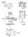
- FIG. 1 shows several individual parts of the hinge proposed by the invention in the pulled-apart state. These are the individual parts that are attached to the wall of the cabinet.
- a blind hole with the usual diameter of 35 mm is first introduced.
- a pot element 12 is then let into the blind hole and is pressed in, for example, and then screwed on.
- the pot element 12 contains a plate 13 intended to rest on the inside of the wall 11 of the cabinet, in which screw holes may be present.
- a cover element 14 is then applied to this pot element 12, for example inserted.
- the support arm element 15 shown in FIG. 1 is then attached to the pot element in such a way that it is at least partially arranged in the pot.
- the support arm element 15 contains the actual support arm 16, which has two side walls 21 in its central region.
- the functional element is inserted between the side walls 21 and has two parallel spaced webs 19, 20 in its front area 18 facing the front edge of the cabinet. An insert can be inserted between these webs Has joint axes.
- the support arm element 16 is inserted with its side walls 21 and the lower part of the functional element 17 into the pot element 12. In this state it is then attached.
- the functional element 17 is supported on the support arm 16 so as to be adjustable upwards and downwards in FIG.
- the pot element 12 contains a flat cylindrical pot 22 to be inserted into the bore, the outside of which is circular, while the inside has the shape of an oval formed by two parallel tendon-like inner walls 23.
- the pot 22 continues upwards into the plate part 13 lying on the wall 11.
- the plate part 13 is approximately U-shaped, the two legs each forming a web 24 which runs parallel to the inner walls 23.
- the plate 13 In the area protruding from the pot 22, the plate 13 is provided with a hole 25, through which a screw can be inserted, with which the plate 13 can be screwed onto the wall 11 of the cabinet.
- the pot has a relatively thin bottom 26.
- the webs 24 protrude slightly beyond the circular outside of the pot 22 and thereby form a stop which determines the exact positioning of the pot in the wall 11.
- both the front end of the webs 24 and the rear end of the plate 13 are undercut.
- FIG. 5 now shows a top view of the cover element 14, which is already shown in FIG. 1.
- the cover element 14 contains a shape similar to the plate 13, ie it is roughly U-shaped with two leg-like webs 27 which belong over the webs 24 of the plate part 13. Two U-shaped incisions 28 allow access to the holes 25 of the plate part 13. As the section in FIG. 6 shows, the webs 27 are slightly raised in relation to the central part 29, so that there is an abutment for the support arm element 16.
- the middle part 29 of the cover element 14 contains a threaded bore 30 to which the support arm 16 can be screwed.
- the cover element 14 can be pushed laterally onto the plate part 13 of the top element 12, for example.
- the cover element 14 contains undercut guides 31.
- FIGS. 9 to 10 now show the support arm element which can be inserted into the pot element 12 provided with the cover element 14.
- the support arm element contains the actual support arm 16, which has a rectangular shape when viewed from above.
- the support arm contains an elongated hole 32, through which a screw is inserted for its fastening, which screw engages in the threaded bore 30 of the cover element 14.
- the support arm 16 is fastened by tightening the screws.
- the front section 19 of the functional element 17 extends through the support arm 16. In this front section, an insert part 33 with holes for the axes of the hinge is inserted.
- a screw is inserted in the support arm 16, the screw head 34 of which is axially fixed in the support arm 16 but is rotatably fastened.
- the screw head 34 has a recess, for example in the form of a hexagon, so that a key is attached here and the Screw can be rotated.
- the fixing of the screw 35 on the support arm 16 is evident from the section in FIG. 9.
- the screw head 34 has a circumferential groove 36, in which an inwardly projecting flange 37 of the support arm 16 engages.
- the connection between the support arm 16 and the screw head 34 is established, for example, by the screw head 34 being produced in two parts and being inserted into the support arm 16 from both sides. The two parts of the screw head 34 are then connected.
- the screw 35 is rotatably but axially fixed to the support arm 16.
- the support arm 16 has the shape of a U-shaped support in the region of the cross section shown.
- the threaded shaft of the screw 35 extends between the two side ends 38.
- this leads to the fact that the insert 33 of the functional element 17 containing the axes moves perpendicular to the plane of the cabinet wall 11.
- FIG. 10 represents a longitudinal section through the support arm 16 of FIGS. 8 and 9.
- the entire support arm 16 can be adjusted back and forth in the longitudinal direction, ie in the direction of the front edge of the cabinet. For this reason, the side walls 38 of the support arm 16 are somewhat shorter than the inner walls 23 of the pot 22.
- a different cover element 41 of the pot element is used.
- the cover element 41 extends over the entire support arm 16 and can be screwed onto the pot element with the aid of the screw 42 shown in FIG.
- the support arm 43 is arranged below the cover element 41. As can be seen in particular from FIG. 12, it is U-shaped over a large part of its length and contains two side walls 44.
- the two side walls 44 each have a longitudinally extending groove 45 on their inner sides, the two grooves running parallel to one another and have the same distance from the top of the support arm 43.
- a screw 47 In the top 46 of the support arm 43 engages a screw 47 which is axially fixed but rotatably connected to the support arm 43.
- the outer part of the screw 47 engages with a thread in a threaded opening of the cover element 41, the screw being accessible from the outside of the cover element 41, see FIG. 11.
- cover element 41 and support arm 43 results from the section in FIG. 13.
- the inserted screw 42 is intended for screwing into the pot elements.
- the cover element 41 is screwed onto the pot element.
- the support arm 42 can be adjusted somewhat relative to the cup element.
- the functional element is inserted into the grooves 45, its fixing being carried out with the aid of a clamping element which bears against the upper funnel-shaped sections 48 of a transverse groove 49.
- a clamping element which bears against the upper funnel-shaped sections 48 of a transverse groove 49.
- the distance between the axis of the functional element and the inner wall of the cabinet can be changed. It is of course also possible to use a support arm in which there are several such grooves 45.
- FIG. 14 shows a possible functional element 50, as can be used in the support arm of the embodiment according to FIGS. 11 to 13.
- the functional element is intended for a single-axis hinge. It contains a plate-shaped shaft 51, the edges 53 of which are narrower and have a thickness such that they just fit into the grooves 45.
- the functional element contains a U-shaped design 52, the two legs 53 of which each have an aligned bore 54. This hole is intended for pushing through a shaft that forms the axis.
- a blind hole 56 is arranged on the top of the web 51, which is possibly intended for receiving the lower end of the adjusting screw 47.
- the web 51 also contains a threaded bore 57, which is used to screw the locking element 58 shown in FIG.
- a transverse groove 59 is formed on the underside of the web 51, see FIG. 15, into which the locking element 58 is inserted.
- the width of the groove 59 corresponds to the width of the locking element 58.
- a screw is inserted through a central bore 60 of the locking element 58 and screwed into the threaded bore 57.
- the two ends of the locking element 58 have beveled surfaces 61 which cooperate with the oblique sections 48 of the transverse groove 49 in the side walls 44 of the support arm 43.
- the functional element 50 is fixed in the support arm 43.
- the example shown is a single-axis hinge, in which case a pot is used which is open to the end region of the wall 11 of the cabinet to which it is to be attached, so that the functional element can reach through.
- FIGS. 17 to 19 again show a modified embodiment.
- the support arm 70 in turn has a U-shape over part of its length, and in its top, similar to the embodiment in FIG. 10, is a screw head 34 of a screw used.
- a guide body 72 inserted between the side walls 71 of the support arm 70 can be displaced.
- this guide body has two projections on each longitudinal side, which engage in corresponding transverse grooves 74 in the side walls 71. In this way, the guide body is securely guided when the screw head 34 is turned.
- the top and bottom of the guide body 72 is provided with longitudinal grooves 75, which serve to receive the complementary functional element 76, see FIG. 17.
- the functional element is fastened by inserting a screw through it and screwing it into the threaded bore 77 of the guide body 72.
- a functional element 76 can be screwed onto both the underside and the top of the guide body 72. It goes without saying that the functional element 76 also has a central opening through which the adjusting screw can reach.
- FIG. 20 shows a further modified embodiment for fastening a functional element 81 to a support arm, which is not shown again for the sake of simplicity. Only the adjusting screw 35 with its screw head 34 is shown.
- the functional element 81 which in the example shown is also intended for a single-axis hinge, contains a central bore 82 which has a circumferential inwardly projecting flange 83.
- This functional element 81 is used together with a similarly shaped plate part 84 which has the same central bore 85.
- a screw sleeve 86 is inserted, which has an internal thread that can be screwed onto the shaft 40 of the screw 35.
- the screw sleeve 86 contains an outwardly directed circumferential projection 87. If the screw sleeve 86 is inserted between the two parts and the two parts are connected to one another with the aid of screws 88, a structure is formed which can be screwed onto the screw shaft 40. Depending on the desired arrangement of the location of the bore 89 of the functional element forming the axis, the plate element 84 can be attached to one or the other side of the functional element. This also results in a large area of application with a large adjustment possibility. This type of adjustment or attachment of the functional element is not limited to single-axis hinges, but can also be used with two-axis hinges.
- FIG. 21 shows a top view of the functional element 81 of FIG. 20.
- the countersunk bores 90 for the screws 88 are also visible.
- FIG. 22 to 24 show the two-part pot element that is attached to the door.
- the pot element contains a base element 91, see FIG. 22, which is constructed similarly to the pot element of FIG. 2. It contains the actual pot part 92 to be inserted into a blind hole in the form of a flat circular cylinder with a plate 93 attached to the top. This plate contains 93 two countersunk holes 94, through which screws can be inserted, with which the pot part 91 can be screwed.
- the side walls 95 of the pot part are shaped similarly to the central opening of the pot element for the wall of the cabinet, i. H. they have the shape of an oval, which is formed by two arcs, which are connected to one another by straight, parallel, see-like sections 95. An L-shaped groove 96 is formed in each of these see-like side walls 95.
- the plate part 93 On the side facing the edge of the door is on the inside a projection 97 is arranged on the inner wall 95.
- the plate part 93 has a threaded bore 98 approximately in the middle between the two countersunk bores 94.
- An insert 99 which is shown in FIG. 24, is intended for use in the pot part 92 of FIGS. 22 and 23. It has an outer shape complementary to the inner shape of the pot 92. In the area of its front side it contains an opening 100 which corresponds to the shape and arrangement of the projection 97. In the area of its side walls, the insert part 99 is provided with a circular pin-like projection 101, which corresponds in diameter and length to the width and depth of the grooves 96.
- the insert 99 also has a plate part 102 which corresponds approximately to the plate part 93. It contains a hole 103. Two pairs of holes 104, 105 are formed in the insert 99, which are used to push through pins which form the axis of the joint.
- the insert 99 is inserted into the pot part 92 in such a way that the peg-like projections 101 engage in the grooves 76. Then the insert 99 is pushed in until the projection 97 comes to lie in the recess 100.
- the insert 99 is fixed with the aid of a screw inserted through the elongated hole 103 and screwed into the threaded bore 98. Due to the elongated hole 103, it can be adjusted in the longitudinal direction.
Landscapes
- Engineering & Computer Science (AREA)
- Mechanical Engineering (AREA)
- Hinges (AREA)
Applications Claiming Priority (2)
| Application Number | Priority Date | Filing Date | Title |
|---|---|---|---|
| DE3830888 | 1988-09-10 | ||
| DE3830888A DE3830888A1 (de) | 1988-09-10 | 1988-09-10 | Scharnier fuer schranktueren |
Publications (1)
| Publication Number | Publication Date |
|---|---|
| EP0359022A1 true EP0359022A1 (fr) | 1990-03-21 |
Family
ID=6362733
Family Applications (1)
| Application Number | Title | Priority Date | Filing Date |
|---|---|---|---|
| EP89115886A Withdrawn EP0359022A1 (fr) | 1988-09-10 | 1989-08-29 | Charnière pour portes d'armoires |
Country Status (2)
| Country | Link |
|---|---|
| EP (1) | EP0359022A1 (fr) |
| DE (1) | DE3830888A1 (fr) |
Citations (4)
| Publication number | Priority date | Publication date | Assignee | Title |
|---|---|---|---|---|
| AT348371B (de) * | 1973-07-12 | 1979-02-12 | Blum Gmbh Julius | Verstellbares mehrteiliges duebeltopfgehaeuse, insbesondere fuer den moebelbau |
| DE2734017A1 (de) * | 1977-07-28 | 1979-02-15 | Heinze Fa R | Moebelscharnier |
| DE2743322A1 (de) * | 1977-09-27 | 1979-04-05 | Heinze Fa R | Moebelscharnier |
| DE3316048A1 (de) * | 1983-05-03 | 1984-11-08 | Paul Hettich GmbH & Co, 4983 Kirchlengern | Moebelscharnier |
Family Cites Families (7)
| Publication number | Priority date | Publication date | Assignee | Title |
|---|---|---|---|---|
| DE7506779U (de) * | 1975-06-19 | Hettich P & Co | Möbelscharnier | |
| DE6941322U (de) * | 1969-10-24 | 1970-01-29 | Hettich F Kg | Klappenscharnier. |
| DE7208826U (de) * | 1972-03-08 | 1972-05-31 | Oni Metallwarenfabrik Guenter & Co | Möbelscharnier |
| DE2325057C3 (de) * | 1973-05-17 | 1984-01-05 | Fa. Richard Heinze, 4900 Herford | Möbelscharnier |
| AT350934B (de) * | 1974-12-02 | 1979-06-25 | Blum Gmbh Julius | Einstellbares scharnier fuer moebel mit nach unten zu oeffnenden klappen |
| DE2549352C2 (de) * | 1975-11-04 | 1984-08-09 | Karl Lautenschläger KG, Möbelbeschlagfabrik, 6107 Reinheim | Montageelement für Möbelscharniere |
| DE2554130C2 (de) * | 1975-12-02 | 1987-03-26 | Richard Heinze Kunststoff-Spritzgießwerke GmbH & Co, 4900 Herford | Möbelscharnier |
-
1988
- 1988-09-10 DE DE3830888A patent/DE3830888A1/de not_active Withdrawn
-
1989
- 1989-08-29 EP EP89115886A patent/EP0359022A1/fr not_active Withdrawn
Patent Citations (4)
| Publication number | Priority date | Publication date | Assignee | Title |
|---|---|---|---|---|
| AT348371B (de) * | 1973-07-12 | 1979-02-12 | Blum Gmbh Julius | Verstellbares mehrteiliges duebeltopfgehaeuse, insbesondere fuer den moebelbau |
| DE2734017A1 (de) * | 1977-07-28 | 1979-02-15 | Heinze Fa R | Moebelscharnier |
| DE2743322A1 (de) * | 1977-09-27 | 1979-04-05 | Heinze Fa R | Moebelscharnier |
| DE3316048A1 (de) * | 1983-05-03 | 1984-11-08 | Paul Hettich GmbH & Co, 4983 Kirchlengern | Moebelscharnier |
Also Published As
| Publication number | Publication date |
|---|---|
| DE3830888A1 (de) | 1990-03-22 |
Similar Documents
| Publication | Publication Date | Title |
|---|---|---|
| AT1214U1 (de) | Scharnier | |
| DE19728641A1 (de) | Positionsscharnier für Türen | |
| DE3931155A1 (de) | Befestigungsanordnung fuer schubladen-frontblenden | |
| DE2723850A1 (de) | Moebelscharnier | |
| EP3561207B1 (fr) | Moyen de raccordement et partie de meuble | |
| EP0590108B1 (fr) | Charniere de meuble | |
| EP1109983B1 (fr) | Charniere a visser comportant une position d'arret | |
| DE19517924B4 (de) | Möbelbeschlagteil | |
| DE4301873A1 (de) | Scharnier mit Schenkel und Halterung zur Schnellbefestigung | |
| DE1559897C2 (de) | Möbelscharnier mit 170 bis 180° Schwenkwinkel | |
| DE2655749A1 (de) | Moebelscharnier | |
| EP2208843B1 (fr) | Charnière pour une porte | |
| DE2909229C2 (de) | Befestigungsanordnung eines Gelenkscharniers an einem am Korpus eines Möbelstücks vorgesehenen Rahmen | |
| DE2849901A1 (de) | Distanzstueck fuer eine an einem moebelteil befestigbare halteplatte eines moebelscharniers | |
| DE29703607U1 (de) | Betätigungshandhabe | |
| DE2648095A1 (de) | Moebelscharnier | |
| EP0359857B1 (fr) | Goupille de charnière | |
| DE3243805C2 (fr) | ||
| AT393712B (de) | Schliessplatte fuer fenster- und tuerverschluesse od.dgl. | |
| DE2554130A1 (de) | Moebelscharnier | |
| DE3830888A1 (de) | Scharnier fuer schranktueren | |
| EP3871575A1 (fr) | Charnière | |
| DE4103923C2 (fr) | ||
| DE69002342T2 (de) | Befestigungsvorrichtung durch Zusammenschrauben auf einem Profil, insbesondere auf einem Elektrizitätsschrank. | |
| DE2460943A1 (de) | Moebelscharnier |
Legal Events
| Date | Code | Title | Description |
|---|---|---|---|
| PUAI | Public reference made under article 153(3) epc to a published international application that has entered the european phase |
Free format text: ORIGINAL CODE: 0009012 |
|
| AK | Designated contracting states |
Kind code of ref document: A1 Designated state(s): AT DE ES FR IT |
|
| 17P | Request for examination filed |
Effective date: 19900808 |
|
| 17Q | First examination report despatched |
Effective date: 19920123 |
|
| STAA | Information on the status of an ep patent application or granted ep patent |
Free format text: STATUS: THE APPLICATION IS DEEMED TO BE WITHDRAWN |
|
| 18D | Application deemed to be withdrawn |
Effective date: 19920403 |