EP0359084A2 - Verfahren und Vorrichtung zur Herstellung von Kontaktlinsen - Google Patents
Verfahren und Vorrichtung zur Herstellung von Kontaktlinsen Download PDFInfo
- Publication number
- EP0359084A2 EP0359084A2 EP89116310A EP89116310A EP0359084A2 EP 0359084 A2 EP0359084 A2 EP 0359084A2 EP 89116310 A EP89116310 A EP 89116310A EP 89116310 A EP89116310 A EP 89116310A EP 0359084 A2 EP0359084 A2 EP 0359084A2
- Authority
- EP
- European Patent Office
- Prior art keywords
- curve
- machining
- data
- basis
- radius
- Prior art date
- Legal status (The legal status is an assumption and is not a legal conclusion. Google has not performed a legal analysis and makes no representation as to the accuracy of the status listed.)
- Granted
Links
Images




Classifications
-
- G—PHYSICS
- G02—OPTICS
- G02C—SPECTACLES; SUNGLASSES OR GOGGLES INSOFAR AS THEY HAVE THE SAME FEATURES AS SPECTACLES; CONTACT LENSES
- G02C7/00—Optical parts
- G02C7/02—Lenses; Lens systems ; Methods of designing lenses
- G02C7/04—Contact lenses for the eyes
-
- B—PERFORMING OPERATIONS; TRANSPORTING
- B29—WORKING OF PLASTICS; WORKING OF SUBSTANCES IN A PLASTIC STATE IN GENERAL
- B29D—PRODUCING PARTICULAR ARTICLES FROM PLASTICS OR FROM SUBSTANCES IN A PLASTIC STATE
- B29D11/00—Producing optical elements, e.g. lenses or prisms
- B29D11/00932—Combined cutting and grinding thereof
-
- B—PERFORMING OPERATIONS; TRANSPORTING
- B24—GRINDING; POLISHING
- B24B—MACHINES, DEVICES, OR PROCESSES FOR GRINDING OR POLISHING; DRESSING OR CONDITIONING OF ABRADING SURFACES; FEEDING OF GRINDING, POLISHING, OR LAPPING AGENTS
- B24B13/00—Machines or devices designed for grinding or polishing optical surfaces on lenses or surfaces of similar shape on other work; Accessories therefor
- B24B13/0025—Machines or devices designed for grinding or polishing optical surfaces on lenses or surfaces of similar shape on other work; Accessories therefor for contact lenses
-
- B—PERFORMING OPERATIONS; TRANSPORTING
- B29—WORKING OF PLASTICS; WORKING OF SUBSTANCES IN A PLASTIC STATE IN GENERAL
- B29D—PRODUCING PARTICULAR ARTICLES FROM PLASTICS OR FROM SUBSTANCES IN A PLASTIC STATE
- B29D11/00—Producing optical elements, e.g. lenses or prisms
- B29D11/00951—Measuring, controlling or regulating
- B29D11/00961—Measuring, controlling or regulating using microprocessors or computers
-
- G—PHYSICS
- G05—CONTROLLING; REGULATING
- G05B—CONTROL OR REGULATING SYSTEMS IN GENERAL; FUNCTIONAL ELEMENTS OF SUCH SYSTEMS; MONITORING OR TESTING ARRANGEMENTS FOR SUCH SYSTEMS OR ELEMENTS
- G05B19/00—Program-control systems
- G05B19/02—Program-control systems electric
- G05B19/18—Numerical control [NC], i.e. automatically operating machines, in particular machine tools, e.g. in a manufacturing environment, so as to execute positioning, movement or co-ordinated operations by means of program data in numerical form
- G05B19/4097—Numerical control [NC], i.e. automatically operating machines, in particular machine tools, e.g. in a manufacturing environment, so as to execute positioning, movement or co-ordinated operations by means of program data in numerical form characterised by using design data to control NC machines, e.g. CAD/CAM
-
- Y—GENERAL TAGGING OF NEW TECHNOLOGICAL DEVELOPMENTS; GENERAL TAGGING OF CROSS-SECTIONAL TECHNOLOGIES SPANNING OVER SEVERAL SECTIONS OF THE IPC; TECHNICAL SUBJECTS COVERED BY FORMER USPC CROSS-REFERENCE ART COLLECTIONS [XRACs] AND DIGESTS
- Y02—TECHNOLOGIES OR APPLICATIONS FOR MITIGATION OR ADAPTATION AGAINST CLIMATE CHANGE
- Y02P—CLIMATE CHANGE MITIGATION TECHNOLOGIES IN THE PRODUCTION OR PROCESSING OF GOODS
- Y02P90/00—Enabling technologies with a potential contribution to greenhouse gas [GHG] emissions mitigation
- Y02P90/02—Total factory control, e.g. smart factories, flexible manufacturing systems [FMS] or integrated manufacturing systems [IMS]
Definitions
- This invention relates to a method of manufacturing contact lenses which are used while being held in contact with the corneas of eyes to correct the visual acuity of a patient and to an apparatus used in implementing the method.
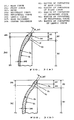
- contact lenses have a shape as shown in Fig. 3(a) or as shown in Fig. 3(b).
- Fig. 3(a) is a fragmentary sectional view of a minus lens used mainly to correct the visual acuity of near-sightedness
- Fig. 3(b) is a fragmentary sectional view of a plus contact lens used mainly to correct the visual acuity of hypermetropia.
- the contact lens has a curved surface 301 called a base curve on the inner side thereof and another curved surface 302 called a front curve on the opposite side.
- the radius of curvature R1 of the base curve 301 is determined so as to adapt to the shape of the cornea of a patient's eye
- the radius of curvature R2 of the front curve 302 is determined of the basis of the radius of curvature R1 of the base curve 301 and the power necessary for the patient.
- the minus power lens shown in Fig. 3(a) has the relationship of R1 ⁇ R2
- the plus power lens shown in Fig. 3(b) has the relationship of R1 > R2.
- R1 R2 the power is substantially O D (diopter).
- a curved surface 303 Formed on the circumference of the base curve 301 is a curved surface 303 called a bevel, and this bevel 303 generally consists of a curved surface 304 called a secondary curve and another curved surface 305 called a peripheral curve.
- the purpose of the bevel 303 is as follows.
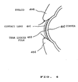
- the contact lens 401 is used normally in the state wherein a tear liquid 403 is interposed between the contact lens and the cornea 402. Since this tear liquid 403 has the important functions of surface cleaning and sterilization of the cornea 402 and supplying oxygen thereto, the tear liquid 403 lying between the contact lens 401 and the cornea 402 is necessary to be changed with a fresh one.
- the bevel 303 is provided for the purpose of causing the tear liquid to flow in and out smoothly and making the vertical movement of the lens smooth, thus, its shape is determined on the basis of prescription data, such as the quantity of tear and the peripheral shape of the cornea of the patient.
- a curved surface 306 Formed on the circumference of the front curve 302 is a curved surface 306 called a lentic curve.
- This lentic curve 306 is provided to give a certain value to an edge thickness 307, thus, its shape is determined on the basis of the radius of curvature R2 of the front curve 302 and the value of a center thickness 308.
- R2 > R5 in the case of the minus power lens
- the value of the edge thickness 307 which significantly influences the patient's feeling of comfort is preferably set to about 0.08 to 0.11 mm for ordinary patients, or about 0.14 to 0.15 mm for patients of advanced age whose eyelid 404 (Fig. 4) has a poor tension.
- the edge of the contact lens is finished to a smooth curved surface to prevent damage to the cornea.
- the connecting portion between the base curve and the bevel and between the front curve and the lentic curve is finished to a smooth curved surface.
- Fig. 5 shows a typical process of the prior art for manufacturing the contact lens.
- design data for a desired shape were prepared on the basis of the prescription data of patient's eyes or a predetermined standard specification, and then, manufacture was carried out on the basis of these design data.
- a raw material (rod) cutting step 501 is incorporated to cut the raw rod into buttons 602 having a thickness larger than a finally-required thickness. If the raw material is supplied as buttons 602, this first step is omitted.
- a base curve cutting step 502 is to cut the button 602 to form the base curve, that is, as shown in Fig. 6(b), a button 602 is secured to a collet chuck 604 and cut by the use of a cutting tool 605 attached to a highprecision CNC lathe or the like, whereby a base curve 606 of desired shape is formed.
- a base curve polishing step 503 is to polish the surface of the base curve to finish to an optical surface, that is, as shown in Fig. 6(c), polishing is carried out by the use of a peculiar polishing tool 607 whose surface shape accords with the desired shape of the base curve. Where the base curve is to have an aspheric surface, sometimes, a very small polishing pad is used.
- a front curve cutting step 504 is to cut the surface opposite to the base curve to form the front curve and the lentic curve, that is, as shown in Fig. 6(d), the base curve side of the button is blocked to a mounting tool 609 with an adhesive agent 608 and the opposite side cut by the use of a cutting tool 610 attached to the high-precision CNC lathe or the like as in the case of the base curve machining, to form the front curve 611 and the lentic curve 612 of desired shape. Then, in a front curve polishing step 505, polishing is carried out by the use of a peculiar polishing tool as in the case of the base curve polishing, to finish to an optical surface.
- a bevel grinding step 506 as shown in Fig. 6(e), an uncut lens 613 is blocked to a mounting tool 615 with an adhesive agent 614 or the like and a circumferential portion of the uncut lens 613 is ground by the use of a peculiar grinding tool 616 having a surface shape conforming to the prescription data of the patient to form the bevel of desired shape, and further, the circumference is cut so as to have a desired lens diameter.
- This step generally consists of forming the secondary curve, forming the peripheral curve, and cutting the circumference.
- edge and the blend portions between the individual curved surfaces are polished and ground to finish to smooth curved surfaces.
- the manufacturing cost is extremely high. Tries to enhance the mass production efficiency and reduce the manufacturing cost by determining the specifications of standard products have been practiced hitherto as described above.
- the radius of curvature of the base curve varies within the range of 7.00 mm to 8.50 mm with a step of 0.05 mm
- the power varies within the range of ⁇ 10.00 D with a step of 0.25 D
- the shape and outer diameter of the bevel, edge thickness, center thickness, etc. vary also. Therefore, the number or kinds of lenses to be prepared as stocks becomes as large as some thousands, this meaning typical multiitem small-quantity production; thus, the production efficiency is poor and it is impossible to reduce the manufacturing cost.
- each contact lens can satisfy only about 90% of all patients, so that for the remainder or about 10% of the patients, it is necessary to manufacture each contact lens so as to have a shape adapted to each patient through ordering.
- additional peculiar tools conforming to individual shapes must be prepared, thus increasing the manufacturing cost and elongating the time necessary for settling the order.
- Another problem with manufacture of the contact lens is that it is difficult to maintain a high degree of accuracy as required and the yield of manufacture is bad. Especial technically, it is difficult to manufacture the contact lens having a desired power with high accuracy.
- the power of the contact lens can be expressed strictly by a function of the radius of curvature R1 of the base curve, the radius of curvature R2 of the front curve and the center thickness, but conventionally, a simple method is adopted in which the difference between the surface refractive power of the front curve and the surface refractive power of the base curve is calculated.
- the machining accuracy for the base curve and front curve is limited to about ⁇ 0.01 mm in terms of the radius of curvature even if a best-precision CNC lathe now available is used and severe accuracy management is practiced. That is, if an error of +0.01 mm occurs during the machining of the base curve and its radius of curvature R1 becomes 8.01 mm, the surface refractive power of the base curve becomes 56.18 D, resulting in an error of -0.07 D with respect to the design value. Since the allowable error of the power is ⁇ 0.12 D, the above error falls within the allowable range.
- the error of the power is an accumulation of the machining error arising during the machining of the base curve and the machining error arising during the machining of the front curve, so that the possibility of the allowable error being cleared is as low as about 50% to 60%, this making the yield bad.
- the base curve and the bevel are portions which come into contact with the cornea of the patient's eye, their shapes are significant for the purposes of improving the feeling of fitting of the contact lens and preventing the afflux of blood to the eye or its inflammation resulting from the use of the contact lens, thereby enhancing medical safety; thus, the accuracy as demanded is very severe.
- the conventional manufacturing method has the following problems because the machining of the bevel is carried out after the machining of the base curve and front curve as shown in Fig. 5.
- the thickness of the contact lens raw material when the base curve and front curve have been machined is very small and lies in the range of about 0.08 to 0.15 mm as described above, upon the pressing of the grinding tool as shown in Fig. 6(e), its stress causes a deformation of the contact lens raw material, thereby preventing accurate formation of the bevel. Since this forming step was hitherto carried out while considering the degree of deformation by the use of the long-term experience and feeling of skilled workers, this manufacturing method provides a very low productivity and a very bad yield.
- polishing of the base curve, front curve, etc. was hitherto carried out using peculiar certain-shaped polishing tools to maintain a demanded accuracy. Therefore, separate polishing tools must be prepared which are adapted in shape individually to the base curve, secondary curve, peripheral curve, front curve and lentic curve, this increasing the number of kinds of polishing tools correspondingly to the kinds of lenses, increasing the manufacturing cost, and demanding changing of the polishing tools upon the changing of the kind of lens, thereby lowering the productivity.
- the base curve is machined and polished with the side of the front curve secured as shown in Fig. 6(b)
- the front curve and lentic curve are machined and polished with the side of the base curve blocked as shown in Fig. 6(d)
- the bevel is machined with the side of the front curve again secured as shown in Fig. 6(e). Therefore, there are three steps of securing the contact lens raw material.
- the securing position tends to shift when the side of the base curve is secured as shown in Fig. 6(d), as a result, the machining position of the front curve deviates, and the optical axis of the front curve comes out of agreement with that of the base curve; thus, the prism defectiveness results and/or the error of the center thickness exceeds the allowable limit.
- the present invention has been devised to solve the foregoing problems of the prior art, thus, it is an object of the present invention to provide a manufacturing method and a manufacturing apparatus which are capable of quickly ma nufacturing any contact lenses of desired shapes with high machining accuracy without increasing the manufacturing cost thereof.
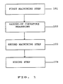
- the design data relating to the shape of the contact lens which include the desired power, radius of curvature of the base curve, radius of curvature of the front curve, diameter, center thickness, edge thickness, radius of the lentic curve, shape of the bevel, etc., are calculated on the basis of the predetermined standard specification and/or the prescription data of patient's eyes.
- the base curve and the bevel are formed on the basis of the design data; in the radius-of-curvature measuring step 102, the radius of curvature of the base curve formed in the first machining step 101 is measured, the design data of the front curve for attainment of a desired power are calculated or the deviation from the foregoing design data is measured on the basis of the measurement data, and the design data of the front curve are calculated by amending the design data of the front curve.
- the front curve and the lentic curve are formed on the basis of the design data.
- the radius of curvature of the lentic curve sometimes becomes equal to the radius of curvature of the front curve, in this case the front curve only is formed.
- the shape of the edge is machined to a smooth curved surface, whereby the contact lens is completed.
- the second manufacturing method of the present invention is indentical with the first manufacturing method except that in the first machining step 101, the front curve, together with the lentic curve if necessary, is formed; in the radius-of-curvature measuring step 102, the radius of curvature of the front curve is measured; and in the second machining step, on the basis of the measurement result, the base curve and the bevel are formed.
- first machining step 101 and the second machining step 103 generally are each composed of the cutting step of cutting the contact lens raw material and the polishing step of polishing the curved surface formed by cut ting, it is not necessary to limit to them if a desired shape can be formed. Further, the edging step 104 can be omitted if the machining of the edge is adequately carried out concurrently in either the first machining step 101 or the second machining step 103.
- the third machining method of the present invention is featured in that in the polishing step of the first machining step 101 and of the second machining step 103, a soft polishing cloth deformable to any shape is pressed against the work while causing relative motion between the polishing cloth and the work, thus, it is possible to carry out polishing with the same means and manhour and with high accuracy irrespective of the shape of the contact lens.
- the fourth manufacturing method of the present invention is featured in that when to block the work to the given mounting tool for the purpose of forming the front curve and the lentic curve in the second machining step 103 after the formation of the base curve and the bevel in the first machining step 101 of the first manufacturing method, the necessary amount of adhesive agent is calculated on the basis of the shape of the base curve of the work, the shape of the mounting tool and the height of adhesion necessary to machine and form the front curve at a proper position, and then, the calculated amount of adhesive agent only is discharged from a storage vessel to bond and block the work to the mounting tool, whereby it is possible to secure the work at a proper position with high accuracy irrespective of the shape of the base curve.
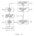
- the specification data output means 201 selects, in accordance with a manufacturing sequence, one out of a plurality of specifica tion data sets entered and supplies it to the first design data calculating means 202 and the second design data calculating means 203.
- the first design data calculating means 202 calculates the first design data for the machining of the base base curve and the bevel to given shapes.
- the first machining means 204 machines the contact lens raw material to form the base curve and the bevel and sends the contact lens raw material having been machined to the radius-of-curvature measuring means 205.
- the radius-of-curvature measuring means 205 measures the base curve, transfers the measurement data to the second design data calculating means 203, and sends the contact lens raw material having been measured to the second machining means 206.
- the second design data calculating means 203 calculates the second design data for the machining of the front curve, and the lentic curve if necessary, to given shapes.
- the second machining means 206 machines the contact lens raw material sent from the radius-of-curvature measuring means 205 to form the front curve, and the lentic curve if necessary, and sends the contact lens raw material having been machined to the edging means 207.
- the edging means 207 machines the edge of the contact lens raw material to a smooth curved surface, whereby the contact lens is completed.
- the second manufacturing apparatus of the present invention is identical with the first manufacturing apparatus except that the first design data calculating means 202 calculates the first design data for the machining of the front curve, and the lentic curve if necessary, to given shapes; the first machining means 204 forms the front curve, and the lentic curve if necessary; the radius-of-curvature measuring means 205 measures the radius of curvature of the front curve; the second design data calculating means 203 calculates the second design data for the machining of the base curve and the bevel to given shapes on the basis of the measurement data and the specification data; and the second machining means 206 forms the base curve and the bevel.
- first machining means 204 and the second machining means 206 generally are each composed of cutting means such as a high-precision CNC lathe and polishing means for polishing a curved surface formed by cutting, it is not necessary to limit to them if the means can form a desired shape. Further, the edging means 207 can be omitted if the first machining means 204 or the second machining means 206 is made of adequate means capable of carrying out the machining of the edge concurrently.
- an unmanned automated manufacturing line can be realized if the specification data calculating means 201, first design data calculating means 202, and second design data calculating means 203 are made of a computer which includes a program for causing it to calculate necessary data automatically and if the first machining means 204, radius-of-curvature measuring means 205, second machining means 206, and edging means 207 are connected together by contact lens raw material auto-conveying means.
- Fig. 7 shows a precision CNC lathe usable in the cutting step of a contact lens raw material according to the present invention.
- the contact lens raw material (hereinafter referred to as a work) 701 to be machined is secured to a collet chuck 702 in a manner similar to the conventional method shown in Fig. 6(b), and this collet chuck 702 is secured to a spindle 703.
- This spindle 703 is rotated at a certain speed in the direction of the arrow 705 by a spindle drive motor 704 and in response thereto, the work 701 is also rotated at a certain speed in a given direction.
- the spindle drive motor 704 is mounted on an X-Y table 706, so that by shifting the X-Y table 706 in the directions of the arrow 708 or X-axis direction and in the directions of the arrow 710 or Y-axis direction, the coordinate position along the X-axis and Y-axis of the work 701 is controlled.
- a cutting tool 711 made of a diamond or the like is mounted on a tool table 712, so that by shifting the tool table 712 in the r-axis direction of a polar coordinate system or in the directions of the arrow 714, the coordinate position along the r-axis of the tool table 712 is controlled.
- the tool table 712 is supported shiftably on a rotary table 715, so that by rotating the rotary table 715 in the directions of the arrow 716, the coordinate position along the ⁇ -axis of the polar coordinate system or the rotational angle of the tool table 712 is controlled.
- the shiftable table 706 and the rotary table 715 are supported on a stationary base 717 shiftable and rotatably, respectively.
- Fig. 8 shows an example of the work whose base curve and bevel were concurrently formed by the use of the cutting means as shown in Fig. 7.
- other parameters such as the shapes of the bevel and lentic curve, the center thickness, and the edge thickness, are determined in accordance with given design data based on the foregoing specification data.
- this cutting step as shown in Fig.
- a groove 804 defining the diameter of the lens was formed concurrently with the formation of the base curve 801, secondary curve 802 and peripheral curve 803 for defining the bevel.
- the individual connecting portions between the base curve 801, secondary curve 802, and peripheral curve 803 are finished into smooth curved surfaces. (This is called "blend”.)
- the groove 804 is formed at a position such that when the front curve and lentic curve are formed in a subsequent step so as to correspond to the dotted line 805, the outer diameter becomes 9.05 mm. With this provision, it became possible to finish the final outer diameter obtained by forming the shape of the edge into a smooth curved surface through edge machining to 9.0 mm.
- the base curve 801 such that the distance t1 from the optical center 806 or most deep portion of the base curve 801 to the front-side end surface 808 of the work 807 take a certain value, it became possible to finish the center thickness t2 of the lens after the formation of the front curve to just the design value.
- the distance t1 be about 2 to 3 mm for the purpose of preventing flexure or deformation of the lens during the machining of the base curve.
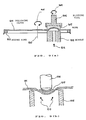
- Fig. 9(a) shows a polishing means for optical polishing the surfaces of the base curve and the bevel, by such means as the cutting means shown in Fig. 7.
- polishing cloth 901 is a polishing cloth mounted to a rotary ring 903 supported rotatably about the center of rotation 902.
- This polishing cloth 901 is made of a soft material deformable into any shape, which is pressed substantially uniformly against the surface of the work 907 blocked to the blocking tool 906 by virtue of the pressure of a fluid, such as compressed air, the fluid being blown against the back side of the polishing cloth 901 through a nozzle 905 as illustrated by the arrow 904.
- the polishing means of the embodiment polishes, while supplying an abrasive agent onto the surface of the polishing cloth 901 under the foregoing condition, the surface of the base curve and the surface of the aspherical bevel concurrently by rotating the rotary ring 903 in the direction of the arrow 908 and at the same time, rotating the work 907 in the direction of the arrow 909, i.e. in the direction opposite to the direction of rotation of the rotary ring 903.
- the material of the polishing cloth 901 is not necessary to be limited as long it is deformable into any shape, and has moderate resiliency and some degree of softness not damaging the surface being polished.
- the efficiency of polishing i.e. the time necessary for polishing and the uniformity of polishing depend on the relative speed between the polishing cloth 901 and the surface being polished that is determined by the rotational speeds of the rotary ring and the work, the pressure of the fluid, etc.
- the pressure of the fluid desirably should fall within the range of about 1x10⁵ to 5x10⁵ Pa (1 to 5 kp/cm2). With these, it is possible to obtain a desired optical surface in an abrasion time of 15 to 30 seconds.
- a desired optical surface was obtained in about 25 seconds through polishing by using a polishing cloth on sale backed with a polyethylene sheet as the polishing cloth 901, supplying a powder of Al2O3 dispersed in water as the abrasive agent, and pressing the polishing cloth 901 against the work 907 of 12.5 mm in outer diameter with the base curve of 7.80 mm in radius of curvature formed therein by applying a compressed air of 19.6 x 10⁴ Pa (2.0 kp/cm2) in pressure.
- the polishing means as shown in Fig. 9(a), it is possible to uniformly press the polishing cloth 901 against the work by means of fluid pressure even where the base curve and bevel have any shapes, the polishing can be carried out with high accuracy, and there is no need to prepare any peculiar polishing tool corresponding in shape to the surface being polished in contrast to the prior art, thereby eliminating the step of changing such a tool; accordingly, it became possible to remarkably reduce a proportion of the manufacturing cost necessary for the polishing step.
- Fig. 9(b) shows an example. This is fundamentally identical with that shown in Fig. 9(a). But, the front curve is convex in a central portion in contrast to the base curve; thus, the fluid pressure in a peripheral portion is relatively low, tending to make it impossible to provide a uniform pressing force. Accordingly, the inner diameter of the nozzle 905 is made larger than the outer diameter of the work 907 so that the fluid can be blown uniformly against the whole surface being polished as illustrated by the arrows 910, this being a different point. With this provision, a similar degree of polishing accuracy to that of the polishing of the base curve was obtained in a similar time.
- Fig. 10 shows a measuring method of measuring the base curve.
- the measuring method uses a conventional optical radius-of-curvature measuring device.
- the device incluvers an optical system for generating a spherical wave having a focal point 1006 and traveling in parallel to a center line 1001, and is configured so that where beams 1002 and 1003 inclined by an angle ⁇ with respect to the center line 1001 enter and reflect symmetrically and where they reflect along their incident paths as they are, a reticular target is clearly focused.
- the incident beams 1002 and 1003 reflect to the opposite sides, whereas when the optical center 1005 of the work 1004 is spaced away from the focal point 1006 by a distance corresponding to the radius of curvature, the incident beams 1002 and 1003 reflect along their incident paths as they are. Therefore, the radius of curvature can be obtained by measuring the distance t3 between the two points at which the reticular target is clearly focused.
- the distance t1 from the optical center 1005 to the front-side end surface 1007 can be readily measured.
- the radius of curvature of the base curve can be obtained by shifting the work 1004 downward beyond an intersection point 1006, and it goes without saying that the radius of curvature of the front curve can be obtained similarly by shifting the work reversely upward.
- Fig. 11 shows a securing method of blocking the work with the base curve and the bevel having been machined and formed to a given mounting tool 1101 in preparation for the machining and forming of the front curve and the lentic curve.
- the mounting tool 1101 is a common tool having an outer diameter of given size and a bonding surface 1105 of given radius of curvature R6, which is used irrespective of the shape of the base curve 1103 and of the bevel 1104 of the work 1102.
- the work 1102 is blocked to the mounting tool 1101 with an adhesive agent 1106.
- thermoplasticity For the adhesive agent being used it is necessary to have thermoplasticity to make it easy to separate the work 1102 from the mounting tool 1101 after machining and it is preferable if it has high viscosity and exhibits only a small variation in volume during cooling and solidifying for the purpose of improving the positioning accuracy at the time of blocking.
- a mixture of paraffin, colophony, EVA, etc. was used.
- the blocking method of the embodiment is characterized in that the thickness t7 of a bonding portion is calculated on the basis of the radius of curvature of the base curve 1103 and its effective diameter t5, and the distance t1 from the optical center 1107 to the front-side end surface 1108 of the work 1102 so as to make constant the distance t6 from the bonding surface 1105 of the mounting tool 1101 to the front-side end surface 1108 of the work 1102, and that a necessary amount adhesive agent is calculated and obtained on the basis of the volume of the space determined by the outer diameter of the mounting tool 1101, the radius of curvature of the bonding surface 1105, the radius of curvature of the base curve and its outer diameter t5, and the thickness t7 of the bonding portion.
- the thus obtained amount of adhesive agent is precisely discharged form a storage container or the like and dropped on the center of the bonding surface 1105 of the mounting tool 1101, the work 1102 is depressed to a given height, and then, the adhesive agent 1106 is solidified.
- the discharge amount of the adhesive agent is controlled, in consideration of the machining and measurement errors of the radius of curvature and the outer diameter of the base curve and the error of the discharge amount of adhesive agent, such that the outer end portion of the adhesive agent 1106 is not located inside the blending zone between the base curve 1103 and the bevel 1104 or such that the outer end portion of the adhesive agent 1106 protrudes at least 0.1 to 0.2 mm outward from the blending zone even where the amount of the adhesive agent is appreciably small.
- the amount of the adhesive agent is controlled such that the outer end portion of the adhesive agent protrudes outward from the blending zone between the base curve and the bevel; therefore, the foregoing problem does not occur.
- Fig. 12 shows an edging means for machining the shape of the circumferential end or edge of the contact lens into a smooth curved surface.
- the work 1201 is secured to the mounting tool 1203 with the adhesive agent 1202 using the blocking method as shown in Fig. 11, and has the front curve and the lentic curve machined and shaped.
- the mounting tool 1203 with the work 1201 attached to it is mounted to the collet chuck 1204 and rotated at a high speed of about 6000 rpm in the direction of the arrow 1206 by the spindle 1205.
- a soft abrasive material having resiliency which is made of moltplane, urethane foam, or the like.
- This polishing material is held by a holder 1208 and driven reciprocatively in the directions of the arrow 1213 by a crankshaft 1212 coupled to a rotary disc 1211 rotated in the direction of the arrow 1210 by a drive motor 1209.
- polishing material 1207 is pressed against the work 1201 with a given pressing force by a pressing means not shown. Accordingly, under this condition the edge can be machined into a desired smooth curved surface by reciprocating the polishing material 1207 four times or so per second at a shift of about 10 mm.
- the shape of the edge can be changed if the extent of deformation is varied by controlling the pressing force of the pressing means not shown, or the curved surface on the front curve side can be made different from that on the base curve side by changing the pressing force between the forward and the backward strokes of the polishing material 1207.
- an unmanned automated manufacturing line can be realized by connecting the individual machining means with auto convey means and effecting centralized control using control means such as a computer.
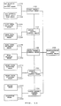
- Fig. 13 shows such an automated manufacturing line.
- Supplied to a manufacturing line control means 1301 are the specification data of contact lenses based on the orders from retail shops and ophthalmic hospitals and based on the stock conditions, and other data, such as delivery date and client (delivery place), necessary for production management.
- the specification data include various data relating to the shape of contact lenses necessary to meet the prescription of patient's eyes, for example, the diameter of the lens, the base curve, and the power for standard products, and additionally, the radius of curvature and the width (inner diameter) of the secondary curve the radius of curvature and the width (inner diameter) of the peripheral curve, the radius of curvature of the lentic curve, the center thickness, and the smoothness of blend for order made products.
- the manhour for data entry can be reduced if the specification data of standard products are previously stored in the manufacturing line control means 1301 and if a ne cessary data part is retrieved upon designation of an item code.
- a first convey/control means 1302 selects a contact lens raw rod of designated material and conveys it to a raw rod cutting means 1303 in accordance with the instruction from the manufacturing line control means 1301.
- the raw rod cutting means 1303 cuts the contact lens raw rod into button works of certain size as shown in Fig. 6(a), and a raw work securing means 1304 bonds and secures the button to a mounting tool as shown in Fig. 6(b).
- the first convey/control means 1302 conveys the thus blocked work to a second convey/control means 1305.
- the second convey/control means 1305 demands the manufacturing line control means 1301 to provide the specification data relating to that work, and calculates the design data relating to the definite shape of the base curve and of the bevel on the basis of the specification data received.
- the design data relating to the optimum shape of the bevel are calculated in accordance with a preset expression on the basis of the outer diameter of the lens and the radius of curvature of the base curve.
- some data may be selected from the data relating to the shape of the bevel that is previously stored per item.
- a base curve machining means 1306 machines and forms the base curve and the bevel using the cutting means as shown in Fig. 7 on the basis of the design data calculated, and a base curve polishing means 1307 polishes the surfaces of the thus formed base curve and bevel using the polishing means as shown in Fig. 9(a).
- the work having been polished is conveyed to a third convey/control means 1308.
- the third convey/control means 1308 conveys the work received to a base curve measuring means 1309, and the base curve measuring means 1309 measures the radius of curvature of the base curve and the like using the method as shown in Fig. 10 and sends the measurement result to the manufacturing line control means 1301.
- a work securing means 1310 secures the work to the blocking or mounting tool using the method as shown in Fig. 11 on the basis of the measurement result.
- the mounting tool secured by the raw work mounting means 1304 ⁇ the foregoing processing> is removed before .
- the third convey/control means 1308 conveys the thus mounted work to a fourth convey/control means 1311.
- the fourth convey/control means 1311 requests the manufacturing line control means 1301 to provide the specification data relating to that work and the measurement result obtained by the base curve measuring means 1309. Then, on the basis of the specification data and the measurement result, the radius of curvature of the front curve for attainment of a desired power and the radius of curvature of the lentic curve for attainment of a desired edge thickness are calculated to obtain the design data relating to the definite shape of the front curve and of the lentic curve.
- a front curve machining means 1312 machines and forms the front curve and the lentic curve using the cutting means as shown in Fig. 7 on the basis of the design data calculated, and a front curve polishing means 1313 polishes the surfaces of the thus formed front curve and lentic curve using the method as shown in Fig. 9(b).
- the work having been polished is conveyed to a fifth convey/control means 1314.
- the fifth convey/control means 1314 conveys the thus received work to an edging means 1315, and this edging means 1315 machines and forms the edge into a smooth curved surface using the method as shown in Fig. 12.
- An inspecting means 1316 inspects the shape, power, presence/absence of scratch, etc. of each curved surface of the contact lens having been machined, and provides the inspection result to the manufacturing line control means 1301.
- the power can be measured automatically using a well-known lens meter, and the shape, presence/absence of scratch, etc. of each curved surface can be inspected automatically using an optical projector and a picture processing device.
- the manufacturing line control means 1301 judges the acceptance/rejection of the products on the basis of the inspection result and if necessary, provides an instruction of re-manufacture. In this way, the situation of a defective product having been manufactured can be dealt with quickly.
- the individual convey/control means have the following functions. That is, when the specification data for a lens of high urgency are entered in the course of manufacture, the manufacturing line control means 1301 instructs each convey/control means to machine this lens first. In responce to this instruction, each convey/control means keeps the work previously received on standby and conveys the work then received of high urgency to each means of machining, polishing or the like. In this way, lenses of high urgency can be manufactured in a very short time by controlling each convey/control means in the foregoing manner.
- the manufacturing line of the embodiment can manufacture the contact lenses of any material and any special shape without any modification of the manufacturing line and those classified as a typical muliitem small-quantity item at low costs.
- the present invention should not be limited to this embodiment. That is, the side of the front curve may be machined first, or the machining of the edge may be carried out concurrently with the machining of the side of the base curve or the front curve, either case leading to the same effectiveness.
- the shape of the curved surface first machined and formed out of the base curve and the front curve is measured and on the basis of the measurement result, the shape of the surface then being machined is determined.
- a machining means which can deal with all contact lenses of various kinds of specification, it is possible to quickly deal with various requests from users in relation to specification to thereby manufacture desired contact lenses. Accordingly, the quality of the contact lens can be enhanced, the manufacturing cost can be reduced, various contact lenses satisfying a variety of prescription of patient's eyes can be manufactured, and any prescription for the contact lens can be settled.
Landscapes
- Engineering & Computer Science (AREA)
- Health & Medical Sciences (AREA)
- Manufacturing & Machinery (AREA)
- Ophthalmology & Optometry (AREA)
- Mechanical Engineering (AREA)
- Physics & Mathematics (AREA)
- General Physics & Mathematics (AREA)
- Human Computer Interaction (AREA)
- Automation & Control Theory (AREA)
- General Health & Medical Sciences (AREA)
- Optics & Photonics (AREA)
- Microelectronics & Electronic Packaging (AREA)
- Grinding And Polishing Of Tertiary Curved Surfaces And Surfaces With Complex Shapes (AREA)
- Eyeglasses (AREA)
Applications Claiming Priority (2)
| Application Number | Priority Date | Filing Date | Title |
|---|---|---|---|
| JP63231969A JP2797333B2 (ja) | 1988-09-16 | 1988-09-16 | コンタクトレンズの製造方法及び装置 |
| JP231969/88 | 1988-09-16 |
Publications (4)
| Publication Number | Publication Date |
|---|---|
| EP0359084A2 true EP0359084A2 (de) | 1990-03-21 |
| EP0359084A3 EP0359084A3 (de) | 1991-03-27 |
| EP0359084B1 EP0359084B1 (de) | 1994-05-11 |
| EP0359084B2 EP0359084B2 (de) | 1998-01-07 |
Family
ID=16931887
Family Applications (1)
| Application Number | Title | Priority Date | Filing Date |
|---|---|---|---|
| EP89116310A Expired - Lifetime EP0359084B2 (de) | 1988-09-16 | 1989-09-04 | Verfahren und Vorrichtung zur Herstellung von Kontaktlinsen |
Country Status (6)
| Country | Link |
|---|---|
| US (1) | US4980993A (de) |
| EP (1) | EP0359084B2 (de) |
| JP (1) | JP2797333B2 (de) |
| KR (1) | KR940000738B1 (de) |
| DE (1) | DE68915233T3 (de) |
| HK (1) | HK101597A (de) |
Cited By (13)
| Publication number | Priority date | Publication date | Assignee | Title |
|---|---|---|---|---|
| EP0439425A1 (de) * | 1990-01-24 | 1991-07-31 | Ciba-Geigy Ag | Vorrichtung zum Herstellen einer Kontaktlinse mit insbesondere asphärischer Vorder- und/oder Rückfläche |
| EP0440578A1 (de) * | 1990-01-24 | 1991-08-07 | Ciba-Geigy Ag | Vorrichtung zur Herstellung einer Formgebungsfläche an einem Formwerkzeug für die Fertigung optischer und ophthalmischer Linsen |
| US5114628A (en) * | 1990-01-24 | 1992-05-19 | Ciba-Geigy Corporation | Method for the manufacture of contact lenses |
| WO1994012342A1 (en) * | 1992-12-02 | 1994-06-09 | Bausch & Lomb Incorporated | Improved method of edging a contact lens or lens blank |
| EP0732639A1 (de) * | 1995-03-17 | 1996-09-18 | Gérard Muller | Verfahren zur Herstellung von Kontaktlinsen |
| US6314199B1 (en) | 1991-12-18 | 2001-11-06 | Novartis Ag | Process and apparatus for examining optical components, especially optical components for the eye and device for illuminating clear-transparent |
| WO2002059682A3 (de) * | 2001-01-24 | 2003-05-30 | Rodenstock Optik G | Verfahren zur herstellung eines brillenglases |
| EP1366858A4 (de) * | 2001-01-05 | 2006-03-15 | Seiko Epson Corp | Poliervorrichtung und -verfahren |
| EP2522458A1 (de) * | 2011-05-13 | 2012-11-14 | ESSILOR INTERNATIONAL (Compagnie Générale d'Optique) | Verfahren zur Bestimmung der Positionsparamter einer hergestellten Oberfläche in Bezug zu einer Referenzoberfläche |
| WO2012142312A3 (en) * | 2011-04-12 | 2013-04-04 | Pixeloptics, Inc. | Adhesive dispensing profile enhancement |
| EP2259741A4 (de) * | 2008-04-01 | 2013-05-29 | Scient Optics Inc | Hinterer oberflächenaufbau von universalkontaktlinsen |
| EP2992393B1 (de) | 2013-04-29 | 2019-09-11 | Essilor International | Berechnungssystem zur herstellung einer ophthalmischen linse |
| CN110268304A (zh) * | 2016-12-30 | 2019-09-20 | 豪雅镜片泰国有限公司 | 用于设计眼镜镜片的方法,镜片,和用于设计镜片的装置 |
Families Citing this family (34)
| Publication number | Priority date | Publication date | Assignee | Title |
|---|---|---|---|---|
| US5231587A (en) * | 1990-07-12 | 1993-07-27 | Loh Optical Machinery, Inc. | Computer controlled lens surfacer |
| US5646049A (en) | 1992-03-27 | 1997-07-08 | Abbott Laboratories | Scheduling operation of an automated analytical system |
| DE4214326A1 (de) * | 1992-04-30 | 1993-11-04 | Wernicke & Co Gmbh | Vorrichtung zur randbearbeitung von brillenglaesern |
| US5452031A (en) * | 1993-05-05 | 1995-09-19 | Boston Eye Technology, Inc. | Contact lens and a method for manufacturing contact lens |
| JP3734512B2 (ja) * | 1993-12-27 | 2006-01-11 | 株式会社メニコン | コンタクトレンズ外観検査方法および外観検査装置 |
| US5555504A (en) * | 1994-06-10 | 1996-09-10 | Johnson & Johnson Vision Products, Inc. | Production line tracking and quality control system |
| US5696686A (en) * | 1994-06-10 | 1997-12-09 | Johnson & Johnson Vision Products, Inc. | Computer system for quality control correlations |
| US5461570A (en) * | 1994-06-10 | 1995-10-24 | Johnson & Johnson Vision Products, Inc. | Computer system for quality control correlations |
| US5972251A (en) * | 1996-10-16 | 1999-10-26 | Bausch & Lomb Incorporated | Method for blocking a contact lens button |
| SE508822C2 (sv) * | 1997-02-17 | 1998-11-09 | Volvo Ab | Förfarande och anordning för mätning och kvantifiering av ytdefekter på en provyta |
| US6047082A (en) * | 1997-11-14 | 2000-04-04 | Wesley Jessen Corporation | Automatic lens inspection system |
| EP1055138B1 (de) | 1998-01-16 | 2003-04-02 | Bausch & Lomb Incorporated | Verfahren und vorrichtung zum ausrichten der torischen achse |
| JP2000011327A (ja) * | 1998-06-29 | 2000-01-14 | Fujitsu Ltd | 薄膜ヘッドスライダの加工方法及び加工装置 |
| US6595639B1 (en) * | 2000-11-10 | 2003-07-22 | Ocular Sciences, Inc. | Junctionless ophthalmic lenses and methods for making same |
| US7152975B2 (en) * | 2000-11-10 | 2006-12-26 | Cooper Vision, Inc. | Junctionless ophthalmic lenses and methods for making same |
| US6577387B2 (en) | 2000-12-29 | 2003-06-10 | Johnson & Johnson Vision Care, Inc. | Inspection of ophthalmic lenses using absorption |
| RU2230530C1 (ru) * | 2002-12-05 | 2004-06-20 | Распопов Владимир Андреевич | Способ изготовления искусственного хрусталика глаза |
| RU2238060C1 (ru) * | 2003-04-07 | 2004-10-20 | Распопов Владимир Андреевич | Способ изготовления монолитного искусственного хрусталика глаза |
| RU2239391C1 (ru) * | 2003-06-18 | 2004-11-10 | Государственное учреждение Межотраслевой научно-технический комплекс "Микрохирургия глаза" им. акад. С.Н.Федорова | Способ изготовления искусственного хрусталика глаза и искусственный хрусталик глаза |
| RU2242189C1 (ru) * | 2003-08-07 | 2004-12-20 | Государственное учреждение Межотраслевой научно-технический комплекс "Микрохирургия глаза" им. акад. С.Н. Федорова | Способ изготовления искусственного хрусталика глаза и искусственный хрусталик глаза |
| US7059037B2 (en) | 2003-10-02 | 2006-06-13 | Radtek Corporation | Blocking apparatus providing an adjustable offset for precision alignment |
| US20050075060A1 (en) * | 2003-10-02 | 2005-04-07 | Konrad Bergandy | Apparatus for precision alignment during blocking process of lens manufacturing |
| US7011571B2 (en) | 2003-10-02 | 2006-03-14 | Radtek Corporation | Blocking apparatus for lens manufacturing including automatic wax delivery system |
| US7220800B2 (en) * | 2004-04-02 | 2007-05-22 | Adherent Laboratories, Inc. | Water soluble contact lens blocking composition with absorbent disintegrant |
| US7138459B2 (en) * | 2004-04-02 | 2006-11-21 | Adherent Laboratories, Inc. | Water soluble contact lens blocking composition |
| KR100578404B1 (ko) * | 2004-12-23 | 2006-05-10 | 김영규 | 콘택트렌즈 제조장치 |
| MY144506A (en) * | 2005-05-04 | 2011-09-30 | Novartis Ag | Automated inspection of colored contact lenses |
| DE102008060589B4 (de) | 2008-12-05 | 2015-06-03 | Schneider Gmbh & Co. Kg | Verfahren zum Bearbeiten und Berechnen einer als Halbfertigfabrikat ausgebildeten optischen Linse |
| JP5648299B2 (ja) | 2010-03-16 | 2015-01-07 | 株式会社ニコン | 眼鏡販売システム、レンズ企業端末、フレーム企業端末、眼鏡販売方法、および眼鏡販売プログラム |
| WO2014173781A1 (en) * | 2013-04-23 | 2014-10-30 | Essilor International (Compagnie Generale D'optique) | Method for controlling a manufacturing device used in an optical lens manufacturing process |
| FR3042286B1 (fr) * | 2015-10-09 | 2017-12-08 | Essilor Int | Procede d'elaboration d'une consigne d’usinage d'une lentille optique |
| EP3330064B1 (de) | 2016-11-30 | 2025-07-16 | Essilor International | Verfahren zur herstellung eines ophthalmischen gegenstands |
| CN107803745B (zh) * | 2017-11-09 | 2024-09-10 | 深圳市汉匠自动化科技有限公司 | 一种气液压辅助3d仿形研磨机 |
| CN112264859A (zh) * | 2020-10-12 | 2021-01-26 | 李艾清 | 一种服饰纽扣边缘冲压去毛边设备 |
Family Cites Families (7)
| Publication number | Priority date | Publication date | Assignee | Title |
|---|---|---|---|---|
| US3874124A (en) * | 1973-02-20 | 1975-04-01 | Harry C Morgan | Method and apparatus for machining and/or polishing molded elastomer materials |
| US4460275A (en) * | 1977-08-02 | 1984-07-17 | Automated Optics, Inc. | Method and apparatus adapted for automatic or semi-automatic fabrication of ultra-precision opthalmic lenses, e.g., contact lenses |
| WO1979000082A1 (en) * | 1977-08-02 | 1979-02-22 | Automated Optics | Method and apparatus adapted for automatic or semi-automatic fabrication of ultra-precision ophthalmic lenses,e.g.,contact lenses |
| DK338978A (da) * | 1977-08-02 | 1979-02-03 | Automated Optics | Kontaktlinse samt fremgangsmaade og maskine til fremstilling af saadanne linser |
| US4455901A (en) * | 1981-10-09 | 1984-06-26 | Bausch & Lomb Incorporated | Apparatus for controlling lathed contact lens thickness |
| US4787732A (en) * | 1986-04-24 | 1988-11-29 | Nick Siviglia | Contact lens and method of making same |
| US4989316A (en) * | 1987-03-09 | 1991-02-05 | Gerber Scientific Products, Inc. | Method and apparatus for making prescription eyeglass lenses |
-
1988
- 1988-09-16 JP JP63231969A patent/JP2797333B2/ja not_active Expired - Fee Related
-
1989
- 1989-09-04 EP EP89116310A patent/EP0359084B2/de not_active Expired - Lifetime
- 1989-09-04 DE DE68915233T patent/DE68915233T3/de not_active Expired - Fee Related
- 1989-09-08 KR KR1019890013000A patent/KR940000738B1/ko not_active Expired - Fee Related
- 1989-09-14 US US07/407,500 patent/US4980993A/en not_active Expired - Lifetime
-
1997
- 1997-06-26 HK HK101597A patent/HK101597A/en not_active IP Right Cessation
Cited By (23)
| Publication number | Priority date | Publication date | Assignee | Title |
|---|---|---|---|---|
| EP0440578A1 (de) * | 1990-01-24 | 1991-08-07 | Ciba-Geigy Ag | Vorrichtung zur Herstellung einer Formgebungsfläche an einem Formwerkzeug für die Fertigung optischer und ophthalmischer Linsen |
| US5114628A (en) * | 1990-01-24 | 1992-05-19 | Ciba-Geigy Corporation | Method for the manufacture of contact lenses |
| EP0439428A3 (en) * | 1990-01-24 | 1992-06-17 | Ciba-Geigy Ag | Process for the production of contact lenses and contact lens preparation system |
| EP0439425A1 (de) * | 1990-01-24 | 1991-07-31 | Ciba-Geigy Ag | Vorrichtung zum Herstellen einer Kontaktlinse mit insbesondere asphärischer Vorder- und/oder Rückfläche |
| US6314199B1 (en) | 1991-12-18 | 2001-11-06 | Novartis Ag | Process and apparatus for examining optical components, especially optical components for the eye and device for illuminating clear-transparent |
| WO1994012342A1 (en) * | 1992-12-02 | 1994-06-09 | Bausch & Lomb Incorporated | Improved method of edging a contact lens or lens blank |
| US5378412A (en) * | 1992-12-02 | 1995-01-03 | Bausch & Lomb Incorporated | Method of edging a contact lens or lens blank |
| EP0732639A1 (de) * | 1995-03-17 | 1996-09-18 | Gérard Muller | Verfahren zur Herstellung von Kontaktlinsen |
| EP1366858A4 (de) * | 2001-01-05 | 2006-03-15 | Seiko Epson Corp | Poliervorrichtung und -verfahren |
| US7033024B2 (en) | 2001-01-24 | 2006-04-25 | Rodenstock Gmbh | Method for manufacturing an eyeglass lens |
| WO2002059682A3 (de) * | 2001-01-24 | 2003-05-30 | Rodenstock Optik G | Verfahren zur herstellung eines brillenglases |
| EP2259741A4 (de) * | 2008-04-01 | 2013-05-29 | Scient Optics Inc | Hinterer oberflächenaufbau von universalkontaktlinsen |
| US9096026B2 (en) | 2011-04-12 | 2015-08-04 | Mitsui Chemicals, Inc. | Adhesive dispensing profile enhancement |
| WO2012142312A3 (en) * | 2011-04-12 | 2013-04-04 | Pixeloptics, Inc. | Adhesive dispensing profile enhancement |
| WO2012156322A1 (en) * | 2011-05-13 | 2012-11-22 | Essilor International (Compagnie Generale D'optique) | Process for determining position parameters of a manufactured surface relative to a reference surface |
| CN103517784A (zh) * | 2011-05-13 | 2014-01-15 | 依视路国际集团(光学总公司) | 用于确定制造表面相对于参考表面的位置参数的方法 |
| EP2522458A1 (de) * | 2011-05-13 | 2012-11-14 | ESSILOR INTERNATIONAL (Compagnie Générale d'Optique) | Verfahren zur Bestimmung der Positionsparamter einer hergestellten Oberfläche in Bezug zu einer Referenzoberfläche |
| US9291522B2 (en) | 2011-05-13 | 2016-03-22 | Essilor International | Process for determining position parameters of a manufactured surface relative to a reference surface |
| AU2012257790B2 (en) * | 2011-05-13 | 2016-04-21 | Essilor International | Process for determining position parameters of a manufactured surface relative to a reference surface |
| CN103517784B (zh) * | 2011-05-13 | 2017-04-12 | 依视路国际集团(光学总公司) | 用于确定制造表面相对于参考表面的位置参数的方法 |
| EP2992393B1 (de) | 2013-04-29 | 2019-09-11 | Essilor International | Berechnungssystem zur herstellung einer ophthalmischen linse |
| CN110268304A (zh) * | 2016-12-30 | 2019-09-20 | 豪雅镜片泰国有限公司 | 用于设计眼镜镜片的方法,镜片,和用于设计镜片的装置 |
| CN110268304B (zh) * | 2016-12-30 | 2021-04-06 | 豪雅镜片泰国有限公司 | 用于设计眼镜镜片的方法,镜片,和用于设计镜片的装置 |
Also Published As
| Publication number | Publication date |
|---|---|
| EP0359084A3 (de) | 1991-03-27 |
| JP2797333B2 (ja) | 1998-09-17 |
| DE68915233T2 (de) | 1994-10-13 |
| HK101597A (en) | 1997-08-15 |
| EP0359084B1 (de) | 1994-05-11 |
| DE68915233D1 (de) | 1994-06-16 |
| EP0359084B2 (de) | 1998-01-07 |
| JPH0280232A (ja) | 1990-03-20 |
| KR940000738B1 (ko) | 1994-01-28 |
| DE68915233T3 (de) | 1998-04-09 |
| KR900005204A (ko) | 1990-04-13 |
| US4980993A (en) | 1991-01-01 |
Similar Documents
| Publication | Publication Date | Title |
|---|---|---|
| EP0359084A2 (de) | Verfahren und Vorrichtung zur Herstellung von Kontaktlinsen | |
| US4781452A (en) | Modular optical manufacturing system | |
| EP0281754B1 (de) | Verfahren und Vorrichtung zur Herstellung von verordneten Brillengläsern | |
| US5611970A (en) | Method of cast molding toric contact lenses | |
| AU2005318290B2 (en) | Polishing wheel | |
| US6991525B2 (en) | Method and device for the surface machining of workpieces composed of non-brittle materials in optical lens manufacturing and tool for this purpose | |
| CA1299874C (en) | Universal lens polishing tool, polishing apparatus and method of polishing | |
| JPH10175149A (ja) | 眼鏡レンズの製造方法および製造装置 | |
| WO2005084885A1 (ja) | 眼鏡レンズ製造方法及び眼鏡レンズ製造システム | |
| EP1409198B1 (de) | Verfahren zum herstellen von optalmischen linsen | |
| KR100974988B1 (ko) | 안경렌즈의 렌즈면 절삭가공장치, 렌즈면 절삭가공방법 및안경렌즈 | |
| EP0070006A1 (de) | Kontaktlinse | |
| US5042935A (en) | Blanks for making prescription eyeglass lenses | |
| US4170092A (en) | Single-point blocking method of surfacing and edging spectacle lenses | |
| JP2829103B2 (ja) | プラスチックレンズの切削方法及び切削装置 | |
| JP2814495B2 (ja) | コンタクトレンズの製造方法及び製造装置 | |
| US4156328A (en) | Single-point blocking method of surfacing and edging spectacle lenses | |
| JP2814494B2 (ja) | コンタクトレンズの製造方法 | |
| CA1149650A (en) | Method and apparatus adapted for automatic or semi- automatic fabrication of ultra-precision ophthalmic lenses, e.g., contact lenses | |
| JP2001353650A (ja) | ポリッシャーとこれを用いた光学部品の研磨方法および研磨装置 | |
| Dent | Production aspects of single point diamond turning. | |
| JP2729789B2 (ja) | 玉摺機 | |
| CN116829306A (zh) | 用于对光学镜片进行抛光的方法 | |
| MXPA96003307A (es) | Procedimiento y herramienta para la produccion deuna superficie concava a partir de una pieza decristal de anteojos | |
| JPH11114790A (ja) | 光学レンズの製造方法 |
Legal Events
| Date | Code | Title | Description |
|---|---|---|---|
| PUAI | Public reference made under article 153(3) epc to a published international application that has entered the european phase |
Free format text: ORIGINAL CODE: 0009012 |
|
| AK | Designated contracting states |
Kind code of ref document: A2 Designated state(s): DE FR GB |
|
| PUAL | Search report despatched |
Free format text: ORIGINAL CODE: 0009013 |
|
| AK | Designated contracting states |
Kind code of ref document: A3 Designated state(s): DE FR GB |
|
| 17P | Request for examination filed |
Effective date: 19910910 |
|
| 17Q | First examination report despatched |
Effective date: 19930325 |
|
| GRAA | (expected) grant |
Free format text: ORIGINAL CODE: 0009210 |
|
| AK | Designated contracting states |
Kind code of ref document: B1 Designated state(s): DE FR GB |
|
| REF | Corresponds to: |
Ref document number: 68915233 Country of ref document: DE Date of ref document: 19940616 |
|
| ET | Fr: translation filed | ||
| PLBI | Opposition filed |
Free format text: ORIGINAL CODE: 0009260 |
|
| 26 | Opposition filed |
Opponent name: CIBA-GEIGY AG Effective date: 19950201 |
|
| PLAB | Opposition data, opponent's data or that of the opponent's representative modified |
Free format text: ORIGINAL CODE: 0009299OPPO |
|
| PLAB | Opposition data, opponent's data or that of the opponent's representative modified |
Free format text: ORIGINAL CODE: 0009299OPPO |
|
| PLBQ | Unpublished change to opponent data |
Free format text: ORIGINAL CODE: EPIDOS OPPO |
|
| R26 | Opposition filed (corrected) |
Opponent name: NOVARTIS AG PATENT AND TRADEMARK DEPT. Effective date: 19950201 |
|
| PLAW | Interlocutory decision in opposition |
Free format text: ORIGINAL CODE: EPIDOS IDOP |
|
| R26 | Opposition filed (corrected) |
Opponent name: NOVARTIS AG PATENT AND TRADEMARK DEPT. Effective date: 19950201 |
|
| PLAW | Interlocutory decision in opposition |
Free format text: ORIGINAL CODE: EPIDOS IDOP |
|
| PUAH | Patent maintained in amended form |
Free format text: ORIGINAL CODE: 0009272 |
|
| STAA | Information on the status of an ep patent application or granted ep patent |
Free format text: STATUS: PATENT MAINTAINED AS AMENDED |
|
| 27A | Patent maintained in amended form |
Effective date: 19980107 |
|
| AK | Designated contracting states |
Kind code of ref document: B2 Designated state(s): DE FR GB |
|
| ET3 | Fr: translation filed ** decision concerning opposition | ||
| REG | Reference to a national code |
Ref country code: GB Ref legal event code: IF02 |
|
| PGFP | Annual fee paid to national office [announced via postgrant information from national office to epo] |
Ref country code: GB Payment date: 20060830 Year of fee payment: 18 |
|
| PGFP | Annual fee paid to national office [announced via postgrant information from national office to epo] |
Ref country code: DE Payment date: 20060831 Year of fee payment: 18 |
|
| PGFP | Annual fee paid to national office [announced via postgrant information from national office to epo] |
Ref country code: FR Payment date: 20060908 Year of fee payment: 18 |
|
| GBPC | Gb: european patent ceased through non-payment of renewal fee |
Effective date: 20070904 |
|
| PG25 | Lapsed in a contracting state [announced via postgrant information from national office to epo] |
Ref country code: DE Free format text: LAPSE BECAUSE OF NON-PAYMENT OF DUE FEES Effective date: 20080401 |
|
| REG | Reference to a national code |
Ref country code: FR Ref legal event code: ST Effective date: 20080531 |
|
| PG25 | Lapsed in a contracting state [announced via postgrant information from national office to epo] |
Ref country code: FR Free format text: LAPSE BECAUSE OF NON-PAYMENT OF DUE FEES Effective date: 20071001 |
|
| PG25 | Lapsed in a contracting state [announced via postgrant information from national office to epo] |
Ref country code: GB Free format text: LAPSE BECAUSE OF NON-PAYMENT OF DUE FEES Effective date: 20070904 |