EP0359358B2 - Condenseur - Google Patents
Condenseur Download PDFInfo
- Publication number
- EP0359358B2 EP0359358B2 EP89305294A EP89305294A EP0359358B2 EP 0359358 B2 EP0359358 B2 EP 0359358B2 EP 89305294 A EP89305294 A EP 89305294A EP 89305294 A EP89305294 A EP 89305294A EP 0359358 B2 EP0359358 B2 EP 0359358B2
- Authority
- EP
- European Patent Office
- Prior art keywords
- cooling medium
- paths
- side group
- height
- flat tubes
- Prior art date
- Legal status (The legal status is an assumption and is not a legal conclusion. Google has not performed a legal analysis and makes no representation as to the accuracy of the status listed.)
- Expired - Lifetime
Links
Images


Classifications
-
- F—MECHANICAL ENGINEERING; LIGHTING; HEATING; WEAPONS; BLASTING
- F28—HEAT EXCHANGE IN GENERAL
- F28F—DETAILS OF HEAT-EXCHANGE AND HEAT-TRANSFER APPARATUS, OF GENERAL APPLICATION
- F28F9/00—Casings; Header boxes; Auxiliary supports for elements; Auxiliary members within casings
- F28F9/02—Header boxes; End plates
- F28F9/0202—Header boxes having their inner space divided by partitions
- F28F9/0204—Header boxes having their inner space divided by partitions for elongated header box, e.g. with transversal and longitudinal partitions
- F28F9/0209—Header boxes having their inner space divided by partitions for elongated header box, e.g. with transversal and longitudinal partitions having only transversal partitions
- F28F9/0212—Header boxes having their inner space divided by partitions for elongated header box, e.g. with transversal and longitudinal partitions having only transversal partitions the partitions being separate elements attached to header boxes
-
- F—MECHANICAL ENGINEERING; LIGHTING; HEATING; WEAPONS; BLASTING
- F25—REFRIGERATION OR COOLING; COMBINED HEATING AND REFRIGERATION SYSTEMS; HEAT PUMP SYSTEMS; MANUFACTURE OR STORAGE OF ICE; LIQUEFACTION SOLIDIFICATION OF GASES
- F25B—REFRIGERATION MACHINES, PLANTS OR SYSTEMS; COMBINED HEATING AND REFRIGERATION SYSTEMS; HEAT PUMP SYSTEMS
- F25B39/00—Evaporators; Condensers
- F25B39/04—Condensers
-
- F—MECHANICAL ENGINEERING; LIGHTING; HEATING; WEAPONS; BLASTING
- F28—HEAT EXCHANGE IN GENERAL
- F28F—DETAILS OF HEAT-EXCHANGE AND HEAT-TRANSFER APPARATUS, OF GENERAL APPLICATION
- F28F1/00—Tubular elements; Assemblies of tubular elements
- F28F1/02—Tubular elements of cross-section which is non-circular
- F28F1/022—Tubular elements of cross-section which is non-circular with multiple channels
-
- F—MECHANICAL ENGINEERING; LIGHTING; HEATING; WEAPONS; BLASTING
- F28—HEAT EXCHANGE IN GENERAL
- F28F—DETAILS OF HEAT-EXCHANGE AND HEAT-TRANSFER APPARATUS, OF GENERAL APPLICATION
- F28F9/00—Casings; Header boxes; Auxiliary supports for elements; Auxiliary members within casings
- F28F9/02—Header boxes; End plates
- F28F9/0243—Header boxes having a circular cross-section
-
- F—MECHANICAL ENGINEERING; LIGHTING; HEATING; WEAPONS; BLASTING
- F28—HEAT EXCHANGE IN GENERAL
- F28D—HEAT-EXCHANGE APPARATUS, NOT PROVIDED FOR IN ANOTHER SUBCLASS, IN WHICH THE HEAT-EXCHANGE MEDIA DO NOT COME INTO DIRECT CONTACT
- F28D21/00—Heat-exchange apparatus not covered by any of the groups F28D1/00 - F28D20/00
- F28D2021/0019—Other heat exchangers for particular applications; Heat exchange systems not otherwise provided for
- F28D2021/008—Other heat exchangers for particular applications; Heat exchange systems not otherwise provided for for vehicles
- F28D2021/0084—Condensers
-
- F—MECHANICAL ENGINEERING; LIGHTING; HEATING; WEAPONS; BLASTING
- F28—HEAT EXCHANGE IN GENERAL
- F28F—DETAILS OF HEAT-EXCHANGE AND HEAT-TRANSFER APPARATUS, OF GENERAL APPLICATION
- F28F2255/00—Heat exchanger elements made of materials having special features or resulting from particular manufacturing processes
- F28F2255/16—Heat exchanger elements made of materials having special features or resulting from particular manufacturing processes extruded
Definitions
- the present invention relates to a condenser particularly adapted for use in automobile air conditioning systems.
- a "serpentine" type of condenser is well known and widely used, which is made up of a multi-bored flat tube, commonly called “harmonica” tube, bent in zigzag form, and corrugated fins sandwiched between the bent tube walls. In this way a core is constituted.
- the cooling medium path in a condenser is roughly classified into two sections, that is, an inlet side section and an outlet side section.
- the cooling medium In the inlet side section the cooling medium is still in a gaseous state, and in the outlet side section it becomes liquid.
- the area for heat exchange of the inlet side paths should be as large as possible.
- that of the outlet side paths can be relatively small.
- the "serpentine" type condenser consists of a single cooling medium path provided by a single pipe, an increase in the area for heat exchange in the inlet side section increases that of the outlet side section. As a whole the size of the condenser become large.
- the inventors have made an invention relating to a "multi-flow" type condenser instead of the serpentine type, which is disclosed in EP-A-0255313.
- the multi-flow type condenser includes a plurality of tubes arranged in parallel and corrugated fins sandwiched therebetween, and headers connected to opposite ends of the tubes.
- the headers have partitions which divide their inner spaces into at least two sections including an inlet side group of paths and an outlet side group of paths; thereby causing the cooling medium to flow in at least one zigzag pattern.
- the total cross-sectional area of the inlet side group of paths progressively diminishes toward the outlet side group.
- the inlet side section has an optimum area for accommodating the cooling medium in a gaseous state
- the outlet side section has an optimum area for accommodating that in a liquid state.
- the cooling medium undergoes a larger pressure loss, and the efficiency of heat exchange decreases because of the relatively small area for heat exchange. If, however, the area in the outlet side section is excessively reduced as compared with that of the inlet side section, pressure loss is likely to increase on the flow of the cooling medium. The area for heat exchange of the inlet side section becomes too large, thereby slowing down the flow rate of the cooling medium.
- EP-A-O 255313 discloses a condenser for use in automobile air conditioning systems, comprising a plurality of flat tubes and means (corrugated fins) sandwiched between the flat tubes for releasing heat, a pair of hollow headers connected to the end of the flat tubes, an inlet and an outlet being provided in the headers for introducing a cooling medium into the flat tubes and discharging a used cooling medium therefrom, wherein the inner spaces of the headers are divided by partitions so as to form a cooling medium flow path in a zigzag pattern including an inlet side group of paths and an outlet side group of paths. Moreover the cross-sectional area of the outlet side group of paths is smaller than that of the inlet side group of paths.
- the present invention is defined in claim 1.
- the illustrated condenser includes a pluraliiy of flat tubes 1 stacked in parallel and corrugated fins 2 sandwiched between the flat tubes 1.
- the terminating ends of the flat tubes 1 are connected to headers 3 and 4.
- Each flat tube is made of extruded aluminum, having a flat configuration as clearly shown in Figs. 2 to 4.
- the flat tubes can be multi-bored flat tubes, commonly called “harmonica tube” or else, electrically seamed tubes can be used.
- Each corrugated fin 2 has a width identical with that of the flat tube 1.
- the fins 2 and the flat tubes 1 are brazed to each other.
- the fins 2 are provided with louvers 2a on the surface.
- the headers 3, 4 are made up of electrically seamed pipes of aluminum, and each have holes 5 of the same shape as the cross-section of the flat tubes 1 so as to accept the tube ends 1a.
- the inserted tube ends 1a are brazed in the holes 5.
- the headers 3 and 4 are connected to an inlet pipe 6 and an outlet pipe 8, respectively.
- the inlet pipe 6 allows a cooling medium to enter the header 3, and the outlet pipe 8 allows the used cooling medium to discharge.
- the headers 3 and 4 are closed with covers 7 and 9, respectively.
- the reference numerals 13 and 14 denote side places attached to the outermost corrugated fins 2.
- the header 3 has its inner space divided by a partition 10 into two sections, and the header 4 also has two sections divided by a partition 11.
- the whole cooling medium path 12 is divided into an inlet side group (A), an intermediate group (B) and an outlet side group (C) as shown Figs. 1 and 6.
- the cooling medium flows in zigzag patterns throughout the groups (A), (B) and (C).
- the intermediate group (B) has a smaller number of flat tubes 1 (that is. paths) than the inlet side group (A), which means that the cross-sectional area of the intermediate group (B) of paths is smaller than that of-the group (A).
- the outlet side group (C) has a smaller number of flat tubes 1 (that is, the number of cooling medium paths) than the intermediate group (B), which means that the cross-sectional area of the outlet side group, (C) of paths is smaller than that of the group (B).
- the entire cross-sectional area of the outlet side group (C) is 30 to 50% of that of the inlet side group (A). If the percentage is less than 30%, the cross-sectional area of the outlet side group (C) becomes small to increase the pressure loss in the cooling medium. At the same time, the cross-sectional area of the inlet side group becomes large to slow down the flow rate of the cooling medium, thereby reducing the efficiency of heat exchange. If the percentage exceeds 50%, the cross-sectional area of the inlet side group (A) becomes small to increase the pressure loss in the cooling medium. In addition, the area for heat transfer is reduced, thereby reducing the efficiency of heat exchange.
- the entire cross-sectional area of the outlet side group (C) is 35 to 50% of that of the inlet side group (A). As shown in Figs. 7 and 8, this more restricted range exhibits the highest efficiency of heat exchange and the lowest pressure loss in the cooling medium.
- the cooling medium is introduced into the inlet side group (A) through the inlet pipe 6 and flows therethrough. Then the cooling medium turns from the right-hand header 4 and enters the intermediate group (B). Then it turns from the left-hand header 3 and enters the outlet side group (C). Finally the cooling medium is discharged through the outlet pipe 8. In this way the cooling medium flows in zigzag patterns. Air enters the air paths constituted by the corrugated fins 2 in the direction (W) in Fig.2. Heat exchange is effected between the air and the cooling medium flowing through the groups (A), (B) and (C).
- the cooling medium passes through the inlet side group (A), it is still in a gaseous state and has a relatively large volume, which is effectively accommodated in the capacity provided by the paths of the group (A) and keeps contact with the flat tubes 1 in a wide range so that the gaseous cooling medium smoothly condenses and reduces its volume.
- the cooling medium flows through the outlet side group by way of the intermediate group (B), it becomes completely liquid, and has such a reduced volume as to be accommodated in a relatively small cross-sectional area of the outlet side group (C).
- the pressure loss is minimized, thereby enhancing the efficiency of heat exchange.
- the illustrated embodiment has three groups (A), (B) and (C), but the number (N) of groups is not limited to 3.
- the number (N) is 2 to 5 groups for the reason explained below:
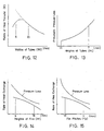
- Figs. 9 to 11 show the results obtained by experiments in which condensers having twenty-four flat tubes are employed, each having a different number of groups.
- a cooling medium is introduced into each of the condensers at the same flow rate.
- Each graph shows the resulting rate of heat exchange and pressure loss in the cooling medium, and changes in the rate of heat exchange and pressure loss with respect to the ratio of the outlet side group to the inlet side group.
- the inlet side group, the intermediate group and the outlet side group have the same cross-sectional area.
- Fig. 9 shows the rates of heat exchange achieved when the speed of wind Vf is 2m/sec and when it is 3m/sec each in front of the condenser. It will be understood from Fig.
- the number (N) of the groups is 2 to 5, the rate of heat exchange is high, and the pressure loss in the cooling medium is low. Thus the ratio between them is well balanced. As described above, it is arranged to ensure that the cross-sectional area of the outlet side group (C) is arranged to have 30 to 50% of that of the inlet side group (A). In addition, the number (N) of the group is arranged to be 2 to 5, which enhances the efficiency of the heat exchange as a result of the reduced pressure loss.
- each flat tube 1 is in the range of 6.0 to 20mm, the height (Ht) thereof is in the range of 1.5 to 7.0mm, the height (Hp) of the cooling medium paths 12 in the flat tubes 1 is 1.0mm or more. It is also arranged that the height (Hf) of the corrugated fins 2 or a distance between the adjacent flat tubes 1 is in the range of 8 to 18mm and that the fin pitch (Fp) is in the range of 1.6 to 4.0mm. The reasons why the above-mentioned ranges are preferable will be described below:
- the width (Wt) of the flat tubes 1 is less than 6.0mm, the corrugated fins 2 sandwiched therebetween will be accordingly narrow in width.
- the narrow width of the corrugated fins 2 limits the size and number of the louvers 2a, which decreases the efficiency of heat exchange.
- the flat tubes 1 are 20mm or more, the corrugated fins 2 sandwiched therebetween will accordingly become large.
- the large fins increases a drag on the flowing air.
- the large fins increases the weight of the condenser. It is therefore preferred that the width (Wt) of the flat tubes is in the range of 6.0 to 16mm, more preferably, 10 to 14mm.
- each flat tube 1 is preferably in the range of 1.5 to 7.0mm. If it exceeds 7.0mm, the pressure loss in the air flow increases. If it is less than 1.5mm, it is difficult to increase the height (Hp) of the air paths by 1.0mm or more because of the limited thickness of the flat tubes. It is preferred that it is in the range of 1.5 to 5.0mm; more preferably, 2.5 to 4.0mm.
- the height (Hp) of the cooling medium flow paths in the flat tubes 1 is preferably 1.0mm or more. If it is less than 1.0mm, the pressure loss in the cooling medium increases, thereby decreasing the rates of heat transfer. It is preferred that it is in the range of 1.5 to 2.0mm.
- the height (Hf) of the corrugated fins 2 is in the range of 6.0 to 16mm. If it is less than 6mm, the pressure loss in the air will increase as shown in Fig. 14. If it exceeds 18mm, the number of total fins decreases, thereby reducing the efficiency of heat exchange.
- the optimum range is 8.0 to 12mm.
- the fin pitches is preferably in the range of 1.6 to 4.0mm. If they are less than 1.6mm, the louvers 2a interfere with the flow of the air, thereby increasing the pressure loss in the air flow. If they exceed 4.0mm, the efficiency of heat exchange decreases. It is therefore preferred that the range is 1.6 to 3.2mm; more preferably. 2.0 to 3.2mm.
- the condensers of the present invention are constructed with the flat tubes, the corrugated fins and the headers in which the widths and heights of the flat tubes, the heights of the cooling medium flow paths, the heights and pitches of the fin are determined at optimum values, thereby reducing the pressure losses which the air and the cooling medium undergo. As a result the efficiency of heat exchanger is enhanced.
- the cross-sectional area of the cooling medium paths 12 progressively diminishes from the inlet side group to the outlet side group through the intermediate group.
- the inlet side group and the intermediate group have the same cross-sectional area which is larger than that of the outlet side group.
- the reduction in the cross-sectional area is effected by reducing the number of the flat tubes, but it is possible to reduce the cross-sectional areas of the individual flat tubes without changing the number thereof.
- the headers 3 and 4 are provided at their erected postures between which the flat tubes 1 are horizontally stacked one above another, but it is possible to modify it to an embodiment in which the headers 3 and 4 are positioned up and down between which the flat tubes are vertically arranged in parallel.
Landscapes
- Engineering & Computer Science (AREA)
- Physics & Mathematics (AREA)
- Thermal Sciences (AREA)
- Mechanical Engineering (AREA)
- General Engineering & Computer Science (AREA)
- Geometry (AREA)
- Heat-Exchange Devices With Radiators And Conduit Assemblies (AREA)
- Valve Device For Special Equipments (AREA)
- Oscillators With Electromechanical Resonators (AREA)
- Vending Machines For Individual Products (AREA)
- Air-Conditioning For Vehicles (AREA)
- Compression-Type Refrigeration Machines With Reversible Cycles (AREA)
- Cooling Or The Like Of Semiconductors Or Solid State Devices (AREA)
Claims (7)
- Condensateur, en particulier destiné à être utilisé dans des systèmes de conditionnement d'air d'automobiles, comprenant une pluralité de tubes plats (1) et d'ailettes ondulées (2) placées en sandwich entre les tubes plats, pour dégager la chaleur, une paire de collecteurs creux (3, 4) raccordés à l'extrémité des tubes plats (1), une entrée (6) et une sortie (8) étant prévues dans les collecteurs (3, 4) pour introduire un fluide de refroidissement dans les tubes plats et pour en évacuer le fluide de refroidissement usé, les espaces intérieurs des collecteurs (3, 4) étant divisés par des cloisons (respectivement 10 et 11), de manière à former un chemin de circulation (12) du fluide de refroidissement en forme de zigzag et comportant un groupe de chemins côté entrée (A) et un groupe de chemins côté sortie (C), le nombre (N) de groupes de chemins étant 2 à 5 et chacun des tubes plats étant réalisé en aluminium extrudé et présentant une pluralité d'alésages (12) s'étendant le long de sa longueur, caractérisé par le fait que la surface de section du groupe de chemins côté sortie (C) est de 30 % à 50 % de celle du groupe de chemins côté entrée (A).
- Condensateur suivant la revendication 1,
caractérisé par le fait que la surface de section du groupe de chemins côté sortie est de 35 % à 50 % de celle du groupe de chemins côté entrée. - Condensateur suivant la revendication 1,
caractérisé par le fait que chaque tube plat présente les dimensions suivantes :largeur 6,0 à 20,0 mm 6,0 à 20,0 mm hauteur 1,5 à 7,0 mm hauteur de chaque chemin de circulation du fluide de refroidissement 1,0 mm ou plus, hauteur 6,0 à 16,0 mm pas d'ailette 1,6 à 4,0 mm - Condensateur suivant la revendication 1,
caractérisé par le fait que chaque tube plat présente les dimensions suivantes :largeur 10 à 14 mm hauteur 2,5 à 4,0 mm hauteur de chaque chemin de circulation du fluide de refroidissement 1,5 à 2,0 mm, hauteur 8,0 à 16,0 mm pas d'ailette 1,6 à à 3,2 mm - Condensateur suivant la revendication 1,
caractérisé par le fait que chaque tube plat présente les dimensions suivantes :largeur 10,0 à 14,0 mm hauteur 2,5 à 4,0 mm hauteur de chaque chemin de circulation du fluide de refroidissement 1,5 à 2,0 mm, hauteur 8,0 à 12,0 mm pas d'ailette 2,0 à 3,2 mm - Condensateur suivant l'une ou l'autre des revendications précédentes, caractérisé par le fait que les moyens de dégagement de chaleur sont des ailettes ondulées (2) pourvues d'auvents (2a) sur leur surface.
- Condensateur suivant l'une ou l'autre des revendications précédentes, caractérisé par le fait que chacun des tubes plats a une section elliptique.
Priority Applications (1)
| Application Number | Priority Date | Filing Date | Title |
|---|---|---|---|
| EP19910201248 EP0448183A3 (fr) | 1988-09-14 | 1989-05-25 | Condenseur |
Applications Claiming Priority (3)
| Application Number | Priority Date | Filing Date | Title |
|---|---|---|---|
| JP12082088 | 1988-09-14 | ||
| JP12082088 | 1988-09-14 | ||
| JP120820/88 | 1988-09-14 |
Related Child Applications (2)
| Application Number | Title | Priority Date | Filing Date |
|---|---|---|---|
| EP19910201248 Division EP0448183A3 (fr) | 1988-09-14 | 1989-05-25 | Condenseur |
| EP91201248.1 Division-Into | 1989-05-25 |
Publications (3)
| Publication Number | Publication Date |
|---|---|
| EP0359358A1 EP0359358A1 (fr) | 1990-03-21 |
| EP0359358B1 EP0359358B1 (fr) | 1996-04-10 |
| EP0359358B2 true EP0359358B2 (fr) | 2001-10-24 |
Family
ID=14795773
Family Applications (2)
| Application Number | Title | Priority Date | Filing Date |
|---|---|---|---|
| EP89305294A Expired - Lifetime EP0359358B2 (fr) | 1988-09-14 | 1989-05-25 | Condenseur |
| EP19910201248 Withdrawn EP0448183A3 (fr) | 1988-09-14 | 1989-05-25 | Condenseur |
Family Applications After (1)
| Application Number | Title | Priority Date | Filing Date |
|---|---|---|---|
| EP19910201248 Withdrawn EP0448183A3 (fr) | 1988-09-14 | 1989-05-25 | Condenseur |
Country Status (6)
| Country | Link |
|---|---|
| EP (2) | EP0359358B2 (fr) |
| KR (2) | KR0184854B1 (fr) |
| AT (1) | ATE136639T1 (fr) |
| AU (1) | AU618840B2 (fr) |
| CA (1) | CA1334796C (fr) |
| DE (1) | DE68926202T3 (fr) |
Families Citing this family (13)
| Publication number | Priority date | Publication date | Assignee | Title |
|---|---|---|---|---|
| DE4020591C2 (de) * | 1990-06-28 | 1995-12-07 | Diesel Kiki Co | Mehrfachdurchfluß-Kondensator |
| FR2665757B1 (fr) * | 1990-08-08 | 1997-01-17 | Valeo Thermique Moteur Sa | Condenseur de fluide refrigerant a circulation verticale, et procede de fabrication. |
| JP3044436B2 (ja) * | 1994-04-21 | 2000-05-22 | 株式会社ゼクセル | 積層型熱交換器 |
| JP3996208B2 (ja) | 1997-05-12 | 2007-10-24 | ノルスク・ヒドロ・アーエスアー | 熱交換器 |
| WO2002081998A1 (fr) | 2001-04-04 | 2002-10-17 | Norsk Hydro Asa | Collecteur d'echangeur thermique |
| US20030102113A1 (en) * | 2001-11-30 | 2003-06-05 | Stephen Memory | Heat exchanger for providing supercritical cooling of a working fluid in a transcritical cooling cycle |
| KR100913141B1 (ko) | 2004-09-15 | 2009-08-19 | 삼성전자주식회사 | 마이크로채널튜브를 이용한 증발기 |
| FR2928448B1 (fr) * | 2008-03-04 | 2015-05-01 | Valeo Systemes Thermiques | Refroidisseur de gaz ameliore |
| EP2369284B1 (fr) * | 2010-03-23 | 2018-01-24 | AKG-Thermotechnik GmbH & Co.KG | Echangeur thermique, notamment pour sèche-linge à condensation |
| JP5609916B2 (ja) * | 2012-04-27 | 2014-10-22 | ダイキン工業株式会社 | 熱交換器 |
| KR101425042B1 (ko) * | 2012-07-26 | 2014-08-01 | 엘지전자 주식회사 | 실외 열교환기 |
| KR102139270B1 (ko) | 2012-09-14 | 2020-07-29 | 리벤트 인터내셔날 아베 | 열풍 오븐 |
| EP2722629A1 (fr) | 2012-10-16 | 2014-04-23 | Behr GmbH & Co. KG | Condensateur |
Family Cites Families (8)
| Publication number | Priority date | Publication date | Assignee | Title |
|---|---|---|---|---|
| US1958226A (en) * | 1932-04-06 | 1934-05-08 | Fedders Mfg Co Inc | Condenser for refrigerating apparatus |
| FR2478807A1 (fr) * | 1980-03-21 | 1981-09-25 | Deville Ste Indle | Boite collectrice de raccordement pour appareil d'echanges thermiques |
| EP0480914A3 (en) * | 1986-07-29 | 1992-05-13 | Showa Aluminum Kabushiki Kaisha | Condenser |
| JPS6334466A (ja) | 1986-07-29 | 1988-02-15 | 昭和アルミニウム株式会社 | 凝縮器 |
| NL8700641A (nl) * | 1987-03-18 | 1988-10-17 | Radson Bv | Ketelelement. |
| EP0283718B1 (fr) * | 1987-03-25 | 1990-09-12 | Johann Schönhammer | Echangeur à contre-courant |
| DE3725602A1 (de) * | 1987-08-01 | 1989-02-09 | Sueddeutsche Kuehler Behr | Flachrohr fuer einen waermetauscher |
| DE3730117C1 (de) * | 1987-09-08 | 1988-06-01 | Norsk Hydro As | Verfahren zum Herstellen eines Waermetauschers,insbesondere eines Kraftfahrzeugkuehlers und Rohrprofil zur Verwendung bei einem derartigen Verfahren |
-
1989
- 1989-05-25 EP EP89305294A patent/EP0359358B2/fr not_active Expired - Lifetime
- 1989-05-25 AT AT89305294T patent/ATE136639T1/de not_active IP Right Cessation
- 1989-05-25 EP EP19910201248 patent/EP0448183A3/fr not_active Withdrawn
- 1989-05-25 DE DE68926202T patent/DE68926202T3/de not_active Expired - Lifetime
- 1989-05-30 CA CA000601106A patent/CA1334796C/fr not_active Expired - Lifetime
- 1989-08-01 KR KR1019890010959D patent/KR0184854B1/ko not_active Expired - Lifetime
- 1989-08-01 KR KR89010959A patent/KR960009342B1/ko not_active Expired - Lifetime
- 1989-08-30 AU AU40915/89A patent/AU618840B2/en not_active Expired
Also Published As
| Publication number | Publication date |
|---|---|
| EP0359358A1 (fr) | 1990-03-21 |
| EP0359358B1 (fr) | 1996-04-10 |
| KR960009342B1 (en) | 1996-07-18 |
| KR900005136A (ko) | 1990-04-13 |
| EP0448183A2 (fr) | 1991-09-25 |
| EP0448183A3 (fr) | 1991-10-16 |
| AU618840B2 (en) | 1992-01-09 |
| KR0184854B1 (en) | 1999-05-01 |
| DE68926202T2 (de) | 1996-09-05 |
| ATE136639T1 (de) | 1996-04-15 |
| DE68926202T3 (de) | 2002-05-16 |
| AU4091589A (en) | 1990-03-22 |
| CA1334796C (fr) | 1995-03-21 |
| DE68926202D1 (de) | 1996-05-15 |
Similar Documents
| Publication | Publication Date | Title |
|---|---|---|
| US5482112A (en) | Condenser | |
| EP0643278B1 (fr) | Evaporateur pour refroidisseurs dans les véhicules automobiles | |
| US5076354A (en) | Multiflow type condenser for car air conditioner | |
| US5458190A (en) | Condenser | |
| EP0479775B1 (fr) | Condenseur | |
| US5529116A (en) | Duplex heat exchanger | |
| EP0359358B2 (fr) | Condenseur | |
| EP2402695B1 (fr) | Évaporateur utilisant des tubes à microcanaux | |
| EP0976999B1 (fr) | Echangeur de chaleur | |
| EP1106951B1 (fr) | Ailette continue combinée pour échangeur de chaleur | |
| US5099913A (en) | Tubular plate pass for heat exchanger with high volume gas expansion side | |
| US4615383A (en) | Serpentine heat exchanging apparatus having corrugated fin units | |
| US6070428A (en) | Stack type evaporator | |
| JP2517872Y2 (ja) | 熱交換器 | |
| JPS6334466A (ja) | 凝縮器 | |
| EP1531309A2 (fr) | Condenseur | |
| JP2891486B2 (ja) | 熱交換器 | |
| JPH0355490A (ja) | 熱交換器 | |
| EP1153256A1 (fr) | Condenseur | |
| EP0803695B1 (fr) | Echangeur de chaleur avec ailettes à plaques | |
| CA1334627C (fr) | Condensateur | |
| JPH0755380A (ja) | 熱交換器 | |
| JPH0195288A (ja) | 熱交換器 | |
| JP3044074B2 (ja) | マルチパス蒸発器 | |
| JPS62131195A (ja) | 熱交換器 |
Legal Events
| Date | Code | Title | Description |
|---|---|---|---|
| PUAI | Public reference made under article 153(3) epc to a published international application that has entered the european phase |
Free format text: ORIGINAL CODE: 0009012 |
|
| AK | Designated contracting states |
Kind code of ref document: A1 Designated state(s): AT DE FR GB SE |
|
| 17P | Request for examination filed |
Effective date: 19900510 |
|
| 17Q | First examination report despatched |
Effective date: 19920127 |
|
| GRAH | Despatch of communication of intention to grant a patent |
Free format text: ORIGINAL CODE: EPIDOS IGRA |
|
| GRAA | (expected) grant |
Free format text: ORIGINAL CODE: 0009210 |
|
| AK | Designated contracting states |
Kind code of ref document: B1 Designated state(s): AT DE FR GB SE |
|
| REF | Corresponds to: |
Ref document number: 136639 Country of ref document: AT Date of ref document: 19960415 Kind code of ref document: T |
|
| XX | Miscellaneous (additional remarks) |
Free format text: TEILANMELDUNG 91201248.1 EINGEREICHT AM 25/05/89. |
|
| REF | Corresponds to: |
Ref document number: 68926202 Country of ref document: DE Date of ref document: 19960515 |
|
| ET | Fr: translation filed | ||
| PLBQ | Unpublished change to opponent data |
Free format text: ORIGINAL CODE: EPIDOS OPPO |
|
| PLBI | Opposition filed |
Free format text: ORIGINAL CODE: 0009260 |
|
| PLAV | Examination of admissibility of opposition |
Free format text: ORIGINAL CODE: EPIDOS OPEX |
|
| PLBI | Opposition filed |
Free format text: ORIGINAL CODE: 0009260 |
|
| PLBQ | Unpublished change to opponent data |
Free format text: ORIGINAL CODE: EPIDOS OPPO |
|
| PLBQ | Unpublished change to opponent data |
Free format text: ORIGINAL CODE: EPIDOS OPPO |
|
| PLAV | Examination of admissibility of opposition |
Free format text: ORIGINAL CODE: EPIDOS OPEX |
|
| PLBI | Opposition filed |
Free format text: ORIGINAL CODE: 0009260 |
|
| 26 | Opposition filed |
Opponent name: LAENGERER & REICH GMBH Effective date: 19961204 |
|
| PLBF | Reply of patent proprietor to notice(s) of opposition |
Free format text: ORIGINAL CODE: EPIDOS OBSO |
|
| 26 | Opposition filed |
Opponent name: LAENGERER & REICH GMBH Effective date: 19961204 Opponent name: BEHR GMBH & CO. Effective date: 19961217 |
|
| 26 | Opposition filed |
Opponent name: VALEO THERMIQUE MOTEUR Effective date: 19970108 Opponent name: BEHR GMBH & CO. Effective date: 19961217 Opponent name: LAENGERER & REICH GMBH Effective date: 19961204 |
|
| PLBF | Reply of patent proprietor to notice(s) of opposition |
Free format text: ORIGINAL CODE: EPIDOS OBSO |
|
| PLBF | Reply of patent proprietor to notice(s) of opposition |
Free format text: ORIGINAL CODE: EPIDOS OBSO |
|
| PLBF | Reply of patent proprietor to notice(s) of opposition |
Free format text: ORIGINAL CODE: EPIDOS OBSO |
|
| RDAH | Patent revoked |
Free format text: ORIGINAL CODE: EPIDOS REVO |
|
| APAC | Appeal dossier modified |
Free format text: ORIGINAL CODE: EPIDOS NOAPO |
|
| APAE | Appeal reference modified |
Free format text: ORIGINAL CODE: EPIDOS REFNO |
|
| APAC | Appeal dossier modified |
Free format text: ORIGINAL CODE: EPIDOS NOAPO |
|
| PLBQ | Unpublished change to opponent data |
Free format text: ORIGINAL CODE: EPIDOS OPPO |
|
| PLAB | Opposition data, opponent's data or that of the opponent's representative modified |
Free format text: ORIGINAL CODE: 0009299OPPO |
|
| R26 | Opposition filed (corrected) |
Opponent name: LAENGERER & REICH GMBH * 19961217 BEHR GMBH & CO. Effective date: 19961204 |
|
| APAC | Appeal dossier modified |
Free format text: ORIGINAL CODE: EPIDOS NOAPO |
|
| PLAW | Interlocutory decision in opposition |
Free format text: ORIGINAL CODE: EPIDOS IDOP |
|
| PUAH | Patent maintained in amended form |
Free format text: ORIGINAL CODE: 0009272 |
|
| STAA | Information on the status of an ep patent application or granted ep patent |
Free format text: STATUS: PATENT MAINTAINED AS AMENDED |
|
| 27A | Patent maintained in amended form |
Effective date: 20011024 |
|
| AK | Designated contracting states |
Kind code of ref document: B2 Designated state(s): AT DE FR GB SE |
|
| REG | Reference to a national code |
Ref country code: GB Ref legal event code: 732E |
|
| XX | Miscellaneous (additional remarks) |
Free format text: TEILANMELDUNG 91201248.1 EINGEREICHT AM 25/05/89. |
|
| REG | Reference to a national code |
Ref country code: GB Ref legal event code: IF02 |
|
| REG | Reference to a national code |
Ref country code: FR Ref legal event code: TP |
|
| REG | Reference to a national code |
Ref country code: FR Ref legal event code: RN |
|
| REG | Reference to a national code |
Ref country code: FR Ref legal event code: FC |
|
| EN | Fr: translation not filed | ||
| ET3 | Fr: translation filed ** decision concerning opposition | ||
| APAH | Appeal reference modified |
Free format text: ORIGINAL CODE: EPIDOSCREFNO |
|
| PGFP | Annual fee paid to national office [announced via postgrant information from national office to epo] |
Ref country code: DE Payment date: 20080529 Year of fee payment: 20 |
|
| PGFP | Annual fee paid to national office [announced via postgrant information from national office to epo] |
Ref country code: AT Payment date: 20080514 Year of fee payment: 20 |
|
| PGFP | Annual fee paid to national office [announced via postgrant information from national office to epo] |
Ref country code: SE Payment date: 20080509 Year of fee payment: 20 |
|
| PGFP | Annual fee paid to national office [announced via postgrant information from national office to epo] |
Ref country code: GB Payment date: 20080528 Year of fee payment: 20 |
|
| REG | Reference to a national code |
Ref country code: GB Ref legal event code: PE20 Expiry date: 20090524 |
|
| EUG | Se: european patent has lapsed | ||
| PG25 | Lapsed in a contracting state [announced via postgrant information from national office to epo] |
Ref country code: GB Free format text: LAPSE BECAUSE OF EXPIRATION OF PROTECTION Effective date: 20090524 |
|
| PGFP | Annual fee paid to national office [announced via postgrant information from national office to epo] |
Ref country code: FR Payment date: 20080514 Year of fee payment: 20 |