EP0359462A1 - Bandaufgabegerät mit statischer Neutralisierungsvorrichtung - Google Patents
Bandaufgabegerät mit statischer Neutralisierungsvorrichtung Download PDFInfo
- Publication number
- EP0359462A1 EP0359462A1 EP89308992A EP89308992A EP0359462A1 EP 0359462 A1 EP0359462 A1 EP 0359462A1 EP 89308992 A EP89308992 A EP 89308992A EP 89308992 A EP89308992 A EP 89308992A EP 0359462 A1 EP0359462 A1 EP 0359462A1
- Authority
- EP
- European Patent Office
- Prior art keywords
- tape
- peeled
- roll
- dispenser
- passive
- Prior art date
- Legal status (The legal status is an assumption and is not a legal conclusion. Google has not performed a legal analysis and makes no representation as to the accuracy of the status listed.)
- Withdrawn
Links
- 230000003068 static effect Effects 0.000 title claims abstract description 26
- 239000010935 stainless steel Substances 0.000 claims abstract description 4
- 229910001220 stainless steel Inorganic materials 0.000 claims abstract description 4
- OKTJSMMVPCPJKN-UHFFFAOYSA-N Carbon Chemical compound [C] OKTJSMMVPCPJKN-UHFFFAOYSA-N 0.000 claims abstract 2
- 239000000835 fiber Substances 0.000 claims abstract 2
- 238000007599 discharging Methods 0.000 claims description 15
- 238000000034 method Methods 0.000 claims description 5
- 230000003472 neutralizing effect Effects 0.000 claims description 4
- 238000000926 separation method Methods 0.000 claims description 3
- 230000005611 electricity Effects 0.000 claims description 2
- 229910052799 carbon Inorganic materials 0.000 claims 1
- 230000006698 induction Effects 0.000 abstract description 5
- 229910000975 Carbon steel Inorganic materials 0.000 abstract 1
- 239000010962 carbon steel Substances 0.000 abstract 1
- 239000010408 film Substances 0.000 description 6
- 239000000853 adhesive Substances 0.000 description 5
- 230000001070 adhesive effect Effects 0.000 description 4
- 230000000694 effects Effects 0.000 description 4
- 229920003023 plastic Polymers 0.000 description 4
- 239000004033 plastic Substances 0.000 description 4
- -1 polyethylene Polymers 0.000 description 3
- 229920000049 Carbon (fiber) Polymers 0.000 description 2
- 229920000298 Cellophane Polymers 0.000 description 2
- 239000004698 Polyethylene Substances 0.000 description 2
- 238000013459 approach Methods 0.000 description 2
- 239000004917 carbon fiber Substances 0.000 description 2
- 238000010276 construction Methods 0.000 description 2
- 150000002500 ions Chemical class 0.000 description 2
- 239000000203 mixture Substances 0.000 description 2
- 238000006386 neutralization reaction Methods 0.000 description 2
- 229920000728 polyester Polymers 0.000 description 2
- 229920000573 polyethylene Polymers 0.000 description 2
- 239000000941 radioactive substance Substances 0.000 description 2
- 239000010409 thin film Substances 0.000 description 2
- 229920002799 BoPET Polymers 0.000 description 1
- 239000005041 Mylar™ Substances 0.000 description 1
- 239000004743 Polypropylene Substances 0.000 description 1
- 239000002390 adhesive tape Substances 0.000 description 1
- 229910052782 aluminium Inorganic materials 0.000 description 1
- XAGFODPZIPBFFR-UHFFFAOYSA-N aluminium Chemical compound [Al] XAGFODPZIPBFFR-UHFFFAOYSA-N 0.000 description 1
- 230000015572 biosynthetic process Effects 0.000 description 1
- 239000004020 conductor Substances 0.000 description 1
- 238000010586 diagram Methods 0.000 description 1
- 230000008030 elimination Effects 0.000 description 1
- 238000003379 elimination reaction Methods 0.000 description 1
- 238000003780 insertion Methods 0.000 description 1
- 230000037431 insertion Effects 0.000 description 1
- 238000004519 manufacturing process Methods 0.000 description 1
- 229910052751 metal Inorganic materials 0.000 description 1
- 239000002184 metal Substances 0.000 description 1
- VNWKTOKETHGBQD-UHFFFAOYSA-N methane Chemical compound C VNWKTOKETHGBQD-UHFFFAOYSA-N 0.000 description 1
- 238000013508 migration Methods 0.000 description 1
- 230000005012 migration Effects 0.000 description 1
- 229920001155 polypropylene Polymers 0.000 description 1
- 230000002285 radioactive effect Effects 0.000 description 1
- 239000012857 radioactive material Substances 0.000 description 1
- 230000000717 retained effect Effects 0.000 description 1
- 125000000391 vinyl group Chemical group [H]C([*])=C([H])[H] 0.000 description 1
- 229920002554 vinyl polymer Polymers 0.000 description 1
Images
Classifications
-
- H—ELECTRICITY
- H05—ELECTRIC TECHNIQUES NOT OTHERWISE PROVIDED FOR
- H05F—STATIC ELECTRICITY; NATURALLY-OCCURRING ELECTRICITY
- H05F3/00—Carrying-off electrostatic charges
-
- Y—GENERAL TAGGING OF NEW TECHNOLOGICAL DEVELOPMENTS; GENERAL TAGGING OF CROSS-SECTIONAL TECHNOLOGIES SPANNING OVER SEVERAL SECTIONS OF THE IPC; TECHNICAL SUBJECTS COVERED BY FORMER USPC CROSS-REFERENCE ART COLLECTIONS [XRACs] AND DIGESTS
- Y10—TECHNICAL SUBJECTS COVERED BY FORMER USPC
- Y10S—TECHNICAL SUBJECTS COVERED BY FORMER USPC CROSS-REFERENCE ART COLLECTIONS [XRACs] AND DIGESTS
- Y10S242/00—Winding, tensioning, or guiding
- Y10S242/906—Static charger or discharger
-
- Y—GENERAL TAGGING OF NEW TECHNOLOGICAL DEVELOPMENTS; GENERAL TAGGING OF CROSS-SECTIONAL TECHNOLOGIES SPANNING OVER SEVERAL SECTIONS OF THE IPC; TECHNICAL SUBJECTS COVERED BY FORMER USPC CROSS-REFERENCE ART COLLECTIONS [XRACs] AND DIGESTS
- Y10—TECHNICAL SUBJECTS COVERED BY FORMER USPC
- Y10S—TECHNICAL SUBJECTS COVERED BY FORMER USPC CROSS-REFERENCE ART COLLECTIONS [XRACs] AND DIGESTS
- Y10S285/00—Pipe joints or couplings
- Y10S285/904—Cryogenic
-
- Y—GENERAL TAGGING OF NEW TECHNOLOGICAL DEVELOPMENTS; GENERAL TAGGING OF CROSS-SECTIONAL TECHNOLOGIES SPANNING OVER SEVERAL SECTIONS OF THE IPC; TECHNICAL SUBJECTS COVERED BY FORMER USPC CROSS-REFERENCE ART COLLECTIONS [XRACs] AND DIGESTS
- Y10—TECHNICAL SUBJECTS COVERED BY FORMER USPC
- Y10S—TECHNICAL SUBJECTS COVERED BY FORMER USPC CROSS-REFERENCE ART COLLECTIONS [XRACs] AND DIGESTS
- Y10S285/00—Pipe joints or couplings
- Y10S285/917—Metallic seals
Definitions
- This invention relates to static neutralizers for roll-type dispensers of pressure-sensitive and adhesive tape prior to application thereof in strip form of selective lengths to the intended article or parts. More particularly, this invention concerns an induction or passive static discharging means for dispensers delivering adhesive as well as non-adhesive backed tapes and film.
- Patent No. 3, 636, 408 there is shown a tape dispenser in combination with a static neutralizer in which a free end of the tape is drawn past a plurality of electrical conductors, such as brushes, transversely disposed across one or both sides thereof and connected to electrical ground.
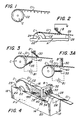
- An example of this prior art system is shown in Figure 2. If a grounding mechanism were not used in this patented system, the brushes would "float" and charge up themselves, thus defining a capacitance preventing further current flow.
- Patent No. 2,264,683 employs a radioactive substance in the dispenser adjacent the free end of the tape to effect neutralization of the static charges by means of alpha rays.
- the disadvantage of this approach is the limited life of the radioactive substance in addition to the restrictions imposed by the NRC upon radioactive materials, the latter preventing the usage ofsuch dispensers by the general public.
- Patent No. 3,128,492 shows a device for neutralizing film by impinging ions of both polarities upon one or both surfaces by means of high voltage static eliminators located vithin the housing and coupled to a power cord for insertion in a line receptacle.
- Still another type of neutralizer presently marketed employs a high voltage air ionizer mounted within the base of the tape dispenser wherein two emitters, one of each polarity, directs air ions generated by corona discharge against the film.
- the problems associated with each of these latter approaches are the large dispenser size to accommodate a power supply, the need to plug into a line power outlet, the proximity of high voltage and very high relative cost.
- Another object of this invention is to provide a static neutralizer for film or tape dispensers which are adapted to be entirely self-contained without requiring a connection to a line voltage source, or to high voltage, or to ground or to a radioactive device.
- Still another object of this invention is to provide a film or tape dispenser which is altogether safe to use.
- the static neutralizing tape dispenser includes first conductive brush means transversely disposed across a surface of the tape and in juxtaposition with a portion thereof radially peeled from a roll rotatably supported in the dispenser, and second conductive brush means in transverse juxtaposition vith an exposed outer surface of the roll which has just been bared by the tape portion previously peeled, the first and second brush means beins electrically interconnected to each other by a conductive path.
- any charge developed on the uncoiled free end of the tape as it is separated from the roll becomes neutralized by the opposite charge generated on the outer surface of the coil from which the free end was detached.
- the first and second brush means may comprise sharp-pointed fine conductive elements, such as stainless steel or carbon fibers, whose ends are adjacently spaced from the corresponding propinquent surface (acting in a manner similar to induction ionizers), or in the form of wiper elements which actually contact the adjacent tape surface (preferrably the outer or non-adhesive face) to define a passive static eliminator.
- sharp-pointed fine conductive elements such as stainless steel or carbon fibers, whose ends are adjacently spaced from the corresponding propinquent surface (acting in a manner similar to induction ionizers), or in the form of wiper elements which actually contact the adjacent tape surface (preferrably the outer or non-adhesive face) to define a passive static eliminator.
- the tape dispenser may be of any suitable size and form, including industrial type units handling tape rolls, for example 4 inches or more in diameter, or narrow 1/2 inch strips of cellophane or polyethylene tapes intended for general public use.
- the dispenser A is conventionally box-shaped in configuration comprised of four enclosing walls 12, 14, 16 and 18 upstanding from a closed bottom 20, as desired.
- a tape roll C having a spindle 22 is horizontally mounted within the dispenser A and is also freely rotatable in notches 24 formed in the side walls 14 and 16.
- the notches 24 are suitably spaced from the bottom so that a complete coil C can be retained within channel 25 defined by said side walls.
- a selected length or strip C1 of tape is radially peeled from the upper portion of the coil C and drawn over a cutting edge 26 mounted on a ledge 28 upstanding from end wall 12.
- the tape may be of the pressure-sensitive type or of any type commonly formed in a coil, such as dry tape which is adapted to be fed from a dispenser.
- a dispenser Typically, and as shown in Figure 1, one of the surfaces of the peeled apart end C1 assumes a charge of one polarity, for example - positive, while the outer surface C2 of the tape still remaining on the coil C from which end C1 is stripped becomes charged to the opposite polarity, for example-negative.
- the static neutralizers B are of the passive discharging or induction ionizing type wherein they are juxtaposed with a charged surface to be neutralized and the charge on that surface is discharged or dissipated as a result of the potential difference between the charged surface and the adjacent end of the neutralizer. That is, by positioning a passive or induction static neutralizer next to a charged surface (either touching or adjacently spaced from such charged surface, these charges are drawn off so that the surface becomes effectively neutralized.
- a conductive brush element 30 is transversely disposed across the free end C1 of the tape and traverses across the upper face thereof during dispensing.
- a second brush element 35 moves across the outside coil surface C2 during unwinding thereof.
- the conductive brushes 30 and 35 may be stainless steel or carbon fiber brushes, such as those shown and described in U.S. Patent Nos. 4,336,535, 4,352,143 or 4,553,191. If the ends of these brushes 30 or 354 actually touch the tape C itself, they preferrably contact a non-adhesive-carrying surface, wherever possible, as shovn in Figure 3.
- the brushes 30 and 35 may just as well be adjacently spaced from corresponding tape portion C1 or C2, as shown in Figure 3A. In either case, the brushes 30 and 35 are not connected to ground but are interconnected through a conductive path 40, which in practice is defined by the mounts and brackets supporting these elements upon the dispenser.
- the brush elements 30 are suspended in suitable clamps from a conductive arm 32 bridging across the dispenser channel 25 by way of bracket 34.
- the bracket 34 is also conductive and is attached to side wall 14 by mounting screws 36.
- a conductive crosspiece 38 forming the lower portion of the bracket 34 extends across the upper portion of the side walls 14 and 16 above the channel 25.
- the brushes 35 are suitably clamped in the end of the crosspiece 38 which faces the tape roll C and are adapted to project within the channel 25 into contiguous disposition with the face C2 of the roll C previously underlying the peeled-away end C1 thereof.
- the conductive path 40 between the upper set of brushes 30 and the roll juxtaposed brushes 35 is defined by the arm 32, the bracket 34 and the crosspiece 38, all of which may be fabricated of a suitable metal, such as aluminum.
- the bracketry supporting both sets of brushes 30 and 35 may be molded of a suitable plastic composition, in which event, because of the insulative characteristic of plastic components, a conductive wire 40 internally or externally threaded in a conventional manner from one set of brushes to the other would define the conductive path interconnecting said brushes.
- brush 30 can be juxtaposed with the upper or lower surface of coil portion C1, as desired.
Landscapes
- Elimination Of Static Electricity (AREA)
- Unwinding Webs (AREA)
- Adhesive Tape Dispensing Devices (AREA)
- Advancing Webs (AREA)
- Gasket Seals (AREA)
Applications Claiming Priority (2)
| Application Number | Priority Date | Filing Date | Title |
|---|---|---|---|
| US243488 | 1988-09-12 | ||
| US07/243,488 US4860159A (en) | 1988-09-12 | 1988-09-12 | Tape dispenser with static neutralizer |
Publications (1)
| Publication Number | Publication Date |
|---|---|
| EP0359462A1 true EP0359462A1 (de) | 1990-03-21 |
Family
ID=22918949
Family Applications (1)
| Application Number | Title | Priority Date | Filing Date |
|---|---|---|---|
| EP89308992A Withdrawn EP0359462A1 (de) | 1988-09-12 | 1989-09-05 | Bandaufgabegerät mit statischer Neutralisierungsvorrichtung |
Country Status (3)
| Country | Link |
|---|---|
| US (2) | US4860159A (de) |
| EP (1) | EP0359462A1 (de) |
| JP (1) | JPH0633126B2 (de) |
Cited By (3)
| Publication number | Priority date | Publication date | Assignee | Title |
|---|---|---|---|---|
| WO1992012612A1 (en) * | 1990-12-26 | 1992-07-23 | Eastman Kodak Company | Web edge discharging system |
| FR2791858A1 (fr) * | 1999-03-31 | 2000-10-06 | Dominique Leprat | Dispositif de diminution des phenomenes electrostatiques parasites |
| EP1208981A1 (de) * | 2000-11-22 | 2002-05-29 | Koenig & Bauer Aktiengesellschaft | Einrichtung zur Vermeidung von Butzen |
Families Citing this family (21)
| Publication number | Priority date | Publication date | Assignee | Title |
|---|---|---|---|---|
| GB2243882B (en) * | 1990-04-25 | 1993-09-01 | Metalrax Group Plc | Gaskets |
| US5716082A (en) * | 1995-09-07 | 1998-02-10 | The Perkin-Elmer Corporation | Fluid conveying device with removable connection |
| US5799493A (en) * | 1996-09-05 | 1998-09-01 | Helix Technology Corporation | Corrosion resistant cryopump |
| US6247703B1 (en) * | 1997-08-29 | 2001-06-19 | Interface Solutions, Inc. | High-pressure compression-failure resistant and high sealing gasket |
| US6626439B1 (en) * | 1997-08-29 | 2003-09-30 | Interface Solutions, Inc. | Edge coated gaskets and method of making same |
| US6138936A (en) * | 1998-04-06 | 2000-10-31 | Em Microelectronic-Marin Sa | Method of using ionized air to remove from a coil the electrostatic charges produced by winding of the coil on a core |
| US6220605B1 (en) | 1998-07-14 | 2001-04-24 | Caterpillar Inc. | Slip joint connection for engine exhaust system |
| AU2001243399A1 (en) | 2000-03-06 | 2001-09-17 | Interface Solutions, Inc. | Gaskets with controlled flange surface adhesion properties |
| WO2002008642A2 (en) * | 2000-07-26 | 2002-01-31 | Interface Solutions, Inc. | Gasket with selectively positioned seal enhancement zones |
| DE10252141A1 (de) * | 2002-11-09 | 2004-07-01 | Prominent Dosiertechnik Gmbh | Flachdichtungsring |
| USD502508S1 (en) | 2004-03-17 | 2005-03-01 | James C. M. Hung | Hand-held tape dispenser |
| US20050230446A1 (en) * | 2004-04-19 | 2005-10-20 | Weiss Paul E | Tape dispenser device which neutralizes a static charge from the tape and method therefor |
| US20080296848A1 (en) * | 2007-06-01 | 2008-12-04 | Taylor Innovations, L.L.C. | Annular sealing member with enhanced hoop strength |
| WO2009017674A2 (en) * | 2007-07-30 | 2009-02-05 | Henkel Ag & Co. Kgaa | Spacer sealant articles |
| US8169453B2 (en) * | 2008-07-31 | 2012-05-01 | Eastman Kodak Company | Thermally conductive, electrically isolated peel member assembly |
| AU2010357053A1 (en) * | 2010-07-07 | 2013-01-24 | Sca Hygiene Products Ab | Apparatus for dispensing absorbent sheet products and method for modifying such apparatus |
| US9410630B1 (en) | 2013-05-06 | 2016-08-09 | Taylor Innovations Llc | Sealing member for use in non-simmering clean service relief valve |
| KR101453444B1 (ko) * | 2013-05-27 | 2014-10-23 | 재단법인 포항산업과학연구원 | 고온진공용기의 실링구조 |
| DE102021103612A1 (de) | 2021-02-16 | 2022-08-18 | InnoDo AG | Klebebandroller und Aufsatz für einen Klebebandroller |
| TWI753810B (zh) * | 2021-04-09 | 2022-01-21 | 王裕達 | 手持式膠帶台 |
| EP4717546A1 (de) * | 2024-09-25 | 2026-04-01 | LEITNER S.p.A. | Luftseiltransportsystem mit einer bürstenvorrichtung zur erdung des förderseils |
Citations (2)
| Publication number | Priority date | Publication date | Assignee | Title |
|---|---|---|---|---|
| US3636408A (en) * | 1970-05-26 | 1972-01-18 | Technical Tape Corp | Tape dispenser with static electricity neutralizer |
| EP0074032A2 (de) * | 1981-09-03 | 1983-03-16 | BASF Aktiengesellschaft | Magnetbandanordnung mit mindestens einem Bandführungselement und Magnetbandkassette mit einer solchen Magnetbandanordnung |
Family Cites Families (23)
| Publication number | Priority date | Publication date | Assignee | Title |
|---|---|---|---|---|
| DE63682C (de) * | C. FROMM in Stuttgart, Augustenstr. 82 | Flantschendichtung mit zwei concentrischen Dichtungsringen und dazwischen Hegender federnden Metalleinlage | ||
| DE149719C (de) * | ||||
| US857134A (en) * | 1906-04-23 | 1907-06-18 | Elmer A Wilcox | Gasket. |
| US1782014A (en) * | 1927-08-10 | 1930-11-18 | Rimmelspacher Joseph | Packing gasket |
| US1846401A (en) * | 1929-10-30 | 1932-02-23 | Victor Mfg & Gasket Co | Gasket |
| DE688252C (de) * | 1932-02-12 | 1940-02-16 | Eisenwerke Akt Ges Deutsche | Elastischer Dichtungsring fuer gusseiserne Muffenrohre mit Stopfbuechse |
| DE720039C (de) * | 1935-12-14 | 1942-04-22 | Gustav Huhn Fa | Dichtung, bestehend aus einem Graphit- oder Graphitkohlering mit metallischem Mantel |
| FR799313A (fr) * | 1935-12-14 | 1936-06-11 | Anciens Etablissements Somborn | Bague d'étanchéité cuirassée munie de bords profilés pour joint de canalisation |
| US2205010A (en) * | 1937-11-26 | 1940-06-18 | St Regis Paper Co | Belt packer |
| US2264683A (en) * | 1939-04-27 | 1941-12-02 | Western Union Telegraph Co | Method of and means for neutralizing electrostatic charges on moving tapes and the like |
| US2249127A (en) * | 1939-10-16 | 1941-07-15 | Frederick W Goetze | Composite gasket and casing therefor |
| US2327837A (en) * | 1942-04-06 | 1943-08-24 | United Conveyor Corp | Gasket |
| US3128492A (en) * | 1961-10-23 | 1964-04-14 | Frank E Hanscom | Device for cleaning photographic film by rotating brushes and by the neutralization of static on the film |
| US3167324A (en) * | 1963-03-13 | 1965-01-26 | Victor Mfg & Gasket Co | Grommet unit |
| US3396917A (en) * | 1966-03-01 | 1968-08-13 | Du Pont | Method for unwinding rolls |
| US3951418A (en) * | 1974-01-21 | 1976-04-20 | W. S. Shamban & Co. | Moving captive seal construction usable under high temperature and cryogenic conditions |
| FR2261462A1 (en) * | 1974-02-19 | 1975-09-12 | Limouzi Jean Maurice | Compression seal including a plastic (PTFE) gasket - to compensate for small variations in joint depth |
| US4336535A (en) * | 1980-04-16 | 1982-06-22 | Ncr Corporation | Cursor for plasma shift register display |
| US4352143A (en) * | 1980-05-27 | 1982-09-28 | Kenkichi Uno | Device for discharging static electricity and method of producing the same |
| US4383694A (en) * | 1981-03-09 | 1983-05-17 | Raimondi S.P.A. | Gasket for statically sealing high pressure and temperature fluids |
| US4553191A (en) * | 1982-12-03 | 1985-11-12 | Xerox Corporation | Static eliminator |
| US4418918A (en) * | 1983-03-14 | 1983-12-06 | Helix Technology Corporation | Static seal device with plastically deformable metal for cryogenic refrigerators |
| US4549741A (en) * | 1984-06-04 | 1985-10-29 | Metex Corporation | Combination metal and knitted wire mesh gasket |
-
1988
- 1988-09-12 US US07/243,488 patent/US4860159A/en not_active Expired - Fee Related
-
1989
- 1989-09-05 EP EP89308992A patent/EP0359462A1/de not_active Withdrawn
- 1989-09-06 JP JP1229461A patent/JPH0633126B2/ja not_active Expired - Lifetime
-
1990
- 1990-11-08 US US07/610,455 patent/US5033756A/en not_active Expired - Fee Related
Patent Citations (2)
| Publication number | Priority date | Publication date | Assignee | Title |
|---|---|---|---|---|
| US3636408A (en) * | 1970-05-26 | 1972-01-18 | Technical Tape Corp | Tape dispenser with static electricity neutralizer |
| EP0074032A2 (de) * | 1981-09-03 | 1983-03-16 | BASF Aktiengesellschaft | Magnetbandanordnung mit mindestens einem Bandführungselement und Magnetbandkassette mit einer solchen Magnetbandanordnung |
Cited By (4)
| Publication number | Priority date | Publication date | Assignee | Title |
|---|---|---|---|---|
| WO1992012612A1 (en) * | 1990-12-26 | 1992-07-23 | Eastman Kodak Company | Web edge discharging system |
| US5400208A (en) * | 1990-12-26 | 1995-03-21 | Eastman Kodak Company | Web edge discharging system |
| FR2791858A1 (fr) * | 1999-03-31 | 2000-10-06 | Dominique Leprat | Dispositif de diminution des phenomenes electrostatiques parasites |
| EP1208981A1 (de) * | 2000-11-22 | 2002-05-29 | Koenig & Bauer Aktiengesellschaft | Einrichtung zur Vermeidung von Butzen |
Also Published As
| Publication number | Publication date |
|---|---|
| JPH0633126B2 (ja) | 1994-05-02 |
| JPH02225265A (ja) | 1990-09-07 |
| US5033756A (en) | 1991-07-23 |
| US4860159A (en) | 1989-08-22 |
Similar Documents
| Publication | Publication Date | Title |
|---|---|---|
| US4860159A (en) | Tape dispenser with static neutralizer | |
| US3636408A (en) | Tape dispenser with static electricity neutralizer | |
| US3757164A (en) | Neutralizing device | |
| US5638249A (en) | Electrostatic support system | |
| JPH024904B2 (de) | ||
| US4526357A (en) | Electro-static sheet feeding method and apparatus | |
| JPS5532079A (en) | Transfer menber holding method | |
| EP0055984B1 (de) | Verfahren und Vorrichtung um Erzeugen einer relativ hohen Ladung auf die Ladung haltenden Materialien | |
| US3318751A (en) | Apparatus for forming metal-paper laminate electrostatically | |
| US20140078637A1 (en) | Apparatus and Method for Neutralizing Static Charge on Both Sides of a Web Exiting an Unwinding Roll | |
| GB2065982B (en) | Roller electrode for use in apparatus for treating plastic film with high voltage corona discharge | |
| JP2622821B2 (ja) | 除帯電電極構造 | |
| US6674631B2 (en) | Charging dispenser for a thin web | |
| US2948353A (en) | Gas-cleaning precipitator | |
| JPS558606A (en) | Storage unit of magnetic record and so on | |
| JPS63301495A (ja) | 帯電走行物体の除電方法 | |
| SU1725408A1 (ru) | Устройство дл устранени статического электричества | |
| JP3732547B2 (ja) | 交流式イオン生成装置 | |
| KR920014700A (ko) | 자기테이프에 정전하를 대전시킴으로서 로울의 와인드 특성을 개선하기 위한 장치 | |
| EP0234903B1 (de) | Elektrostatographisches Kopieren | |
| JP2003243198A (ja) | 静電気除却装置 | |
| JPS59103324A (ja) | コンデンサ用金属蒸着フイルムの非蒸着部形成方法及び装置 | |
| JPS62219496A (ja) | 自己放電式除電器の繊維折れ並に抜け防止装置 | |
| JPH04502B2 (de) | ||
| JP2004229342A (ja) | 静電吸着装置 |
Legal Events
| Date | Code | Title | Description |
|---|---|---|---|
| PUAI | Public reference made under article 153(3) epc to a published international application that has entered the european phase |
Free format text: ORIGINAL CODE: 0009012 |
|
| 17P | Request for examination filed |
Effective date: 19890928 |
|
| AK | Designated contracting states |
Kind code of ref document: A1 Designated state(s): BE CH DE FR GB IT LI NL SE |
|
| STAA | Information on the status of an ep patent application or granted ep patent |
Free format text: STATUS: THE APPLICATION IS DEEMED TO BE WITHDRAWN |
|
| 18D | Application deemed to be withdrawn |
Effective date: 19920201 |