EP0359570A2 - Leckaufspürgerät - Google Patents
Leckaufspürgerät Download PDFInfo
- Publication number
- EP0359570A2 EP0359570A2 EP89309359A EP89309359A EP0359570A2 EP 0359570 A2 EP0359570 A2 EP 0359570A2 EP 89309359 A EP89309359 A EP 89309359A EP 89309359 A EP89309359 A EP 89309359A EP 0359570 A2 EP0359570 A2 EP 0359570A2
- Authority
- EP
- European Patent Office
- Prior art keywords
- container
- detecting
- leak
- sealing
- pressure
- Prior art date
- Legal status (The legal status is an assumption and is not a legal conclusion. Google has not performed a legal analysis and makes no representation as to the accuracy of the status listed.)
- Withdrawn
Links
Images
Classifications
-
- G—PHYSICS
- G01—MEASURING; TESTING
- G01M—TESTING STATIC OR DYNAMIC BALANCE OF MACHINES OR STRUCTURES; TESTING OF STRUCTURES OR APPARATUS, NOT OTHERWISE PROVIDED FOR
- G01M3/00—Investigating fluid-tightness of structures
- G01M3/02—Investigating fluid-tightness of structures by using fluid or vacuum
- G01M3/04—Investigating fluid-tightness of structures by using fluid or vacuum by detecting the presence of fluid at the leakage point
- G01M3/24—Investigating fluid-tightness of structures by using fluid or vacuum by detecting the presence of fluid at the leakage point using infrasonic, sonic or ultrasonic vibrations
Definitions
- This invention relates to a leak detecting apparatus, for detecting a leak in a container completely surrounding an enclosed volume, which container includes, e.g. a sealed pipeline or a container such as an oil drum, a gas cylinder, a vacuum chamber or a decompression chamber, and to a method of detecting a leak in a container.
- Well known methods of detecting a leak in a container include the following:
- a container such as a sealed pipeline or a container may be pressurised in order to listen for sound emitted by colliding molecules passing out through a leak in the container.
- the disadvantage of this method is that a leak caused by a hole smaller than about 0.5mm. may be difficult to detect, especially in the presence of background noise.
- the sound emitted by colliding molecules extends into the ultrasonic region, therefore in order to increase the sensitivity of this method, an ultrasonic receiver may be used to detect a small leak.
- the sensitivity of this method is limited by background ultrasonic or "pink" noise, on top of which may be added ultrasonic noise emitted by other sources, e.g. by pneumatic equipment often found in a working environment such as a garage, laboratory or a factory.
- a further disadvantage of this method is that the receiver must be scanned around the container in which a leak is to be detected, or the receiver must be held stationary and the container moved about the receiver.
- An extremely small leak may be detected in a container such as a vacuum chamber placed under vacuum (at typically 1 Pa) with a mass spectrometer connected to an ionisation gauge head positioned inside the chamber.
- a leak is detected by passing a tube releasing gas e.g. helium over the container and looking for peaks in the helium line detected on the spectrometer.
- a tube releasing gas e.g. helium
- this method is time consuming, expensive and may not easily be automated.
- a further method involves submerging a container such as a pressurised container into a water bath or coating the container with a soap film, so that a leak may be detected by visually inspecting air bubbles coming from the leak.
- the disadvantages of this method is that an operator must be present to inspect the bubbles and also an inconveniently long time may be sent setting up the apparatus. Automation is again difficult to achieve.
- a "pressure decay” method may be employed, wherein a sealed container is placed in an evacuated or pressurised chamber, and then the pressure inside the chamber is monitored in order to record the increase or decrease in pressure with time. This method may again be time consuming especially where a small leak (e.g. a hole less than about 0.5mm in diameter) is involved.
- a leak detecting apparatus and method of detecting leaks is provided.
- the positioning of a sound detector within a container improves the sensitivity of the sound detector by using the container itself as a barrier to external noise. This is particularly important in environments where a lot of noisy equipment is present. Also if desired, high pressure differences can be applied, depending on the container, in order to detect very small apertures.
- a leak detecting apparatus for detecting a leak in a container, such as an oil drum, to be tested, comprising ultrasound detecting means; ultrasound measuring means with an operative connection to said detecting means; means for altering gas pressure; and sealing means for sealing the container; the detecting means being disposed on one side of said sealing means and the measuring means being disposed on another side of said sealing means; the means for altering gas pressure and the said operative connection being disposed within and extending through said sealing means from said one side to said other side; whereby the detecting means can be placed within the container thereby sealing the container and the means for altering gas pressure can provide a difference in gas pressure between the inside and the outside of the container.
- Any suitable ultrasound detecting means may be employed but preferably an ultrasonic receiver such as a piezoelectric transducer is employed.
- the sound detecting means is preferably positioned within said container by automatic positioning means, such as by pneumatic or hydraulic means actuable by e.g. computer control.
- the pressure within the container may be changed, with respect to that outside of the container, by either increasing the pressure within the container or more preferably by reducing the pressure within the container.
- the air within the container may be mixed with or more preferably replaced by an inert gas, such as helium, to improve the transmission of sound within the container.
- an inert gas such as helium
- the container should absorb most of the sound impinging on the outside however, sound insulation may be placed around the container if necessary. Any suitable sound insulation material may be employed such as a mineral fibre.
- a method of detecting a leak in a container by providing a difference in the gas pressure between the inside and the ouside of the container and monitoring the ultrasonic emission produced by a leak of gas from the higher pressure side to the lower pressure side, characterised in that a combination of ultrasonic monitoring means and means for causing the pressure difference are introduced into the container itself through an opening therein and sealed, a pressure difference is supplied and ultrasonic emissions are detected inside the container itself.
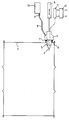
- a leak detecting apparatus to be used specifically on an oil drum 1 of typically up to 200 litres capacity, positioned within a work station (not shown).
- An ultrasonic transducer 2 e.g. a Dawe Instruments Ltd type No.8902C, is mounted on the end of a housing 3.
- the housing is attached to a control head 4, which head 4 is connected to a pneumatic piston 5, so that the transducer 2 may be inserted into or withdrawn from a tapping 6 in the top of the oil drum 1.
- An 'O' ring seal 7 is secured to the head 4 to make an air tight seal between the top of the head 4 and the top of the tapping 6.
- a gas line 8 is included within the housing 3 and head 4.
- the gas line 8 terminates at an opening in the housing 3 and extends from the head 4 to be coupled to a valve 9. From the valve 9 the gas line 8 connects to a gas cylinder 10 containing e.g., helium or compressed air.
- An electrical measuring device 11 is electrically connected to the transducer 2. The measuring device 11 is further connected to a level detector/trigger amplifier circuit 12.
- the oil drum 1 to be tested is automatically fed into the work station.
- the oil drum 1 is then rotated until a proximity sensor (not shown) locates the position of the tapping 6 beneath the control head 4.
- the head 4 is then lowered by control of the pneumatic piston 5 so that the head 4 makes an air tight seal with the tapping 6.
- the valve 9 is automatically opened in order to allow helium gas or compressed air into the oil drum 1 up to a pressure of about 41364 Pa (6 p.s.i). at which pressure the valve 9 is closed.
- the presence of helium improves the sound transmission within the oil drum 1 because sound travels approximately three times faster in helium than in air.
- a leak in the oil drum 1, e.g. caused by a hole of about 0.4mm diameter is immediately detected by the transducer 2, due to the ultrasonic radiation emitted by colliding gas molecules rushing out of the oil drum though holes or fractures in the container of the oil drum 1.
- a measured electrical signal, from the transducer 2 is sent to the level detecting/trigger amplifier circuit 12 whereupon either a pass. indicating no detectable leak, or a fail signal is sent to a control to pass or reject the oil drum 1.
- a further advantage of this technique is that a computer can be programmed to test various types of containers, e.g. different sized oil drums.
- a leak could be detected in a gas line by positioning sound detecting means in situ within said gas line at important points such as close to joints or valves. Measuring means operationally connected to said sound detecting means could then send an early warning signal to a control to shut down a particular section of said gas line if a leak were detected.
Landscapes
- Physics & Mathematics (AREA)
- General Physics & Mathematics (AREA)
- Examining Or Testing Airtightness (AREA)
Applications Claiming Priority (2)
| Application Number | Priority Date | Filing Date | Title |
|---|---|---|---|
| GB888821492A GB8821492D0 (en) | 1988-09-14 | 1988-09-14 | Leak detecting apparatus |
| GB8821492 | 1988-09-14 |
Publications (2)
| Publication Number | Publication Date |
|---|---|
| EP0359570A2 true EP0359570A2 (de) | 1990-03-21 |
| EP0359570A3 EP0359570A3 (de) | 1990-12-19 |
Family
ID=10643536
Family Applications (1)
| Application Number | Title | Priority Date | Filing Date |
|---|---|---|---|
| EP19890309359 Withdrawn EP0359570A3 (de) | 1988-09-14 | 1989-09-14 | Leckaufspürgerät |
Country Status (2)
| Country | Link |
|---|---|
| EP (1) | EP0359570A3 (de) |
| GB (1) | GB8821492D0 (de) |
Cited By (4)
| Publication number | Priority date | Publication date | Assignee | Title |
|---|---|---|---|---|
| FR2664054A1 (fr) * | 1990-06-27 | 1992-01-03 | Blagden Ind Plc | Dispositif de controle d'etancheite de recipients. |
| GB2250820A (en) * | 1990-12-12 | 1992-06-17 | Christopher David Hill | Method of and apparatus for detecting leaks in liquid storage tanks acoustically |
| DE102010004737A1 (de) * | 2010-01-14 | 2011-07-21 | Stiebel Eltron GmbH & Co. KG, 37603 | Verfahren und Vorrichtung zur Dichtheitsprüfung eines Warmwasserbehälters |
| US9933327B2 (en) | 2015-08-20 | 2018-04-03 | General Electric Company | Method for detecting leaks in a fuel circuit of a gas turbine fuel supply system |
Family Cites Families (3)
| Publication number | Priority date | Publication date | Assignee | Title |
|---|---|---|---|---|
| US3266296A (en) * | 1963-08-28 | 1966-08-16 | Kelsey Hayes Co | Method and apparatus for inspecting annular workpieces |
| GB1568968A (en) * | 1977-02-07 | 1980-06-11 | Rheem Blagden Ltd | Method and apparatus for testing containers |
| DE3522325A1 (de) * | 1985-06-22 | 1987-01-02 | Battelle Institut E V | Verfahren zur detektion von undichten stellen von behaeltern |
-
1988
- 1988-09-14 GB GB888821492A patent/GB8821492D0/en active Pending
-
1989
- 1989-09-14 EP EP19890309359 patent/EP0359570A3/de not_active Withdrawn
Cited By (4)
| Publication number | Priority date | Publication date | Assignee | Title |
|---|---|---|---|---|
| FR2664054A1 (fr) * | 1990-06-27 | 1992-01-03 | Blagden Ind Plc | Dispositif de controle d'etancheite de recipients. |
| GB2250820A (en) * | 1990-12-12 | 1992-06-17 | Christopher David Hill | Method of and apparatus for detecting leaks in liquid storage tanks acoustically |
| DE102010004737A1 (de) * | 2010-01-14 | 2011-07-21 | Stiebel Eltron GmbH & Co. KG, 37603 | Verfahren und Vorrichtung zur Dichtheitsprüfung eines Warmwasserbehälters |
| US9933327B2 (en) | 2015-08-20 | 2018-04-03 | General Electric Company | Method for detecting leaks in a fuel circuit of a gas turbine fuel supply system |
Also Published As
| Publication number | Publication date |
|---|---|
| GB8821492D0 (en) | 1988-10-12 |
| EP0359570A3 (de) | 1990-12-19 |
Similar Documents
| Publication | Publication Date | Title |
|---|---|---|
| US5052215A (en) | Leak detection in storage tank bottoms by pneumatic enhancement of acoustic emissions | |
| US5526689A (en) | Acoustic emission for detection of corrosion under insulation | |
| US7987720B2 (en) | Ultrasonic sensing array system and method | |
| US2559564A (en) | Pneumatic and air sweep closure | |
| US3838593A (en) | Acoustic leak location and detection system | |
| US4455863A (en) | Sonic detection of gas leaks in underground pipes | |
| SU1281179A3 (ru) | Устройство дл обнаружени утечки | |
| US20040154379A1 (en) | Method and device at testing for leaks and leakage finding | |
| US4507954A (en) | Wraparound used for testing tubing with premixed gases | |
| US3399563A (en) | Method and apparatus for testing the pressure tightness of containers | |
| EP0359570A2 (de) | Leckaufspürgerät | |
| CA1100222A (en) | Ultrasonic leak hole detection apparatus and method | |
| JPS59170739A (ja) | タンクの漏洩検査方法 | |
| CN109298076B (zh) | 一种基于Lamb波的主动式阀门内漏损伤检测系统及方法 | |
| US4453410A (en) | Method and apparatus for locating material defects in hollow bodies | |
| JP2008180536A (ja) | ハウジングなどの漏れ検査装置及び漏れ検査方法 | |
| CN219915491U (zh) | 一种用于岩石自渗吸饱和界面的无损精准测定装置 | |
| EP0219250A2 (de) | Leckdetektor | |
| KR20050098930A (ko) | 누출 감지 방법 및 장치 | |
| JP4968668B2 (ja) | ハウジングなどの漏れ検査装置 | |
| JPH03231132A (ja) | ブレーキキャリパのリークテスタ | |
| CN110220645A (zh) | 深海油气田油气生产泄漏检漏灵敏度实验工艺 | |
| JP3387577B2 (ja) | ビール樽の漏れ検査装置 | |
| CN210567527U (zh) | 深海油气田油气生产泄露误报警实验系统 | |
| KR100830895B1 (ko) | 이동식 밸브 내부누설 진단장치 |
Legal Events
| Date | Code | Title | Description |
|---|---|---|---|
| PUAI | Public reference made under article 153(3) epc to a published international application that has entered the european phase |
Free format text: ORIGINAL CODE: 0009012 |
|
| AK | Designated contracting states |
Kind code of ref document: A2 Designated state(s): AT BE CH DE ES FR GB GR IT LI LU NL SE |
|
| PUAL | Search report despatched |
Free format text: ORIGINAL CODE: 0009013 |
|
| AK | Designated contracting states |
Kind code of ref document: A3 Designated state(s): AT BE CH DE ES FR GB GR IT LI LU NL SE |
|
| 17P | Request for examination filed |
Effective date: 19910619 |
|
| 17Q | First examination report despatched |
Effective date: 19920724 |
|
| STAA | Information on the status of an ep patent application or granted ep patent |
Free format text: STATUS: THE APPLICATION IS DEEMED TO BE WITHDRAWN |
|
| 18D | Application deemed to be withdrawn |
Effective date: 19921204 |