EP0359712A2 - Commutateur à fibres optiques auto-illuminé - Google Patents
Commutateur à fibres optiques auto-illuminé Download PDFInfo
- Publication number
- EP0359712A2 EP0359712A2 EP89810670A EP89810670A EP0359712A2 EP 0359712 A2 EP0359712 A2 EP 0359712A2 EP 89810670 A EP89810670 A EP 89810670A EP 89810670 A EP89810670 A EP 89810670A EP 0359712 A2 EP0359712 A2 EP 0359712A2
- Authority
- EP
- European Patent Office
- Prior art keywords
- actuator
- light
- optical
- switch
- path
- Prior art date
- Legal status (The legal status is an assumption and is not a legal conclusion. Google has not performed a legal analysis and makes no representation as to the accuracy of the status listed.)
- Granted
Links
Images





Classifications
-
- G—PHYSICS
- G02—OPTICS
- G02B—OPTICAL ELEMENTS, SYSTEMS OR APPARATUS
- G02B6/00—Light guides; Structural details of arrangements comprising light guides and other optical elements, e.g. couplings
- G02B6/24—Coupling light guides
- G02B6/26—Optical coupling means
- G02B6/35—Optical coupling means having switching means
- G02B6/3502—Optical coupling means having switching means involving direct waveguide displacement, e.g. cantilever type waveguide displacement involving waveguide bending, or displacing an interposed waveguide between stationary waveguides
- G02B6/3508—Lateral or transverse displacement of the whole waveguides, e.g. by varying the distance between opposed waveguide ends, or by mutual lateral displacement of opposed waveguide ends
-
- G—PHYSICS
- G02—OPTICS
- G02B—OPTICAL ELEMENTS, SYSTEMS OR APPARATUS
- G02B6/00—Light guides; Structural details of arrangements comprising light guides and other optical elements, e.g. couplings
- G02B6/24—Coupling light guides
- G02B6/26—Optical coupling means
- G02B6/35—Optical coupling means having switching means
- G02B6/351—Optical coupling means having switching means involving stationary waveguides with moving interposed optical elements
- G02B6/3512—Optical coupling means having switching means involving stationary waveguides with moving interposed optical elements the optical element being reflective, e.g. mirror
- G02B6/3514—Optical coupling means having switching means involving stationary waveguides with moving interposed optical elements the optical element being reflective, e.g. mirror the reflective optical element moving along a line so as to translate into and out of the beam path, i.e. across the beam path
-
- G—PHYSICS
- G02—OPTICS
- G02B—OPTICAL ELEMENTS, SYSTEMS OR APPARATUS
- G02B6/00—Light guides; Structural details of arrangements comprising light guides and other optical elements, e.g. couplings
- G02B6/24—Coupling light guides
- G02B6/26—Optical coupling means
- G02B6/35—Optical coupling means having switching means
- G02B6/351—Optical coupling means having switching means involving stationary waveguides with moving interposed optical elements
- G02B6/3512—Optical coupling means having switching means involving stationary waveguides with moving interposed optical elements the optical element being reflective, e.g. mirror
- G02B6/352—Optical coupling means having switching means involving stationary waveguides with moving interposed optical elements the optical element being reflective, e.g. mirror the reflective optical element having a shaped reflective surface, e.g. a reflective element comprising several reflective surfaces or facets that function together
-
- G—PHYSICS
- G02—OPTICS
- G02B—OPTICAL ELEMENTS, SYSTEMS OR APPARATUS
- G02B6/00—Light guides; Structural details of arrangements comprising light guides and other optical elements, e.g. couplings
- G02B6/24—Coupling light guides
- G02B6/26—Optical coupling means
- G02B6/35—Optical coupling means having switching means
- G02B6/354—Switching arrangements, i.e. number of input/output ports and interconnection types
- G02B6/3544—2D constellations, i.e. with switching elements and switched beams located in a plane
- G02B6/3548—1xN switch, i.e. one input and a selectable single output of N possible outputs
- G02B6/355—1x2 switch, i.e. one input and a selectable single output of two possible outputs
-
- G—PHYSICS
- G02—OPTICS
- G02B—OPTICAL ELEMENTS, SYSTEMS OR APPARATUS
- G02B6/00—Light guides; Structural details of arrangements comprising light guides and other optical elements, e.g. couplings
- G02B6/24—Coupling light guides
- G02B6/26—Optical coupling means
- G02B6/35—Optical coupling means having switching means
- G02B6/3564—Mechanical details of the actuation mechanism associated with the moving element or mounting mechanism details
- G02B6/3568—Mechanical details of the actuation mechanism associated with the moving element or mounting mechanism details characterised by the actuating force
- G02B6/3574—Mechanical force, e.g. pressure variations
-
- G—PHYSICS
- G02—OPTICS
- G02B—OPTICAL ELEMENTS, SYSTEMS OR APPARATUS
- G02B6/00—Light guides; Structural details of arrangements comprising light guides and other optical elements, e.g. couplings
- G02B6/24—Coupling light guides
- G02B6/26—Optical coupling means
- G02B6/35—Optical coupling means having switching means
- G02B6/3564—Mechanical details of the actuation mechanism associated with the moving element or mounting mechanism details
- G02B6/358—Latching of the moving element, i.e. maintaining or holding the moving element in place once operation has been performed; includes a mechanically bistable system
Definitions
- This invention relates to the field of switches for electrical controls, and more particularly to switches which operate through fibre optic or light guided systems.
- incandescent lamps to provide such indicator lights.
- incandescent lights produce a large quantity of heat which is inefficient an potentially unsafe in closed environments such as airplanes.
- the invention as claimed is intended to remedy these problems. It provides light director in a mechanical actuator to direct light into or away from an output optical path depending on the position of the actuator. Coupling between an optical input and output path or paths are provided by a fibre optic or light-guided control system incorporated at least partly in a mechanical actuator.
- the switched light is used to control electrical circuits and to control the incidence of switched light onto a light indicator.
- the light guide is formed by the casing of the switch itself.
- an optical switch is illustrated generally at 10 in Figure 1. It comprises a housing 11a which is made up of a casing 11 mounted on a switch base 12 and a pushbutton 13 mounted within the casing 11 and being operable to move vertically relative to the casing 11. All of the components are plastic and are moulded using injection moulded techniques.
- An illumination light is provided through a waveguide 34 mounted in switch base 12.
- Latching mechanism 40 comprises a latch groove 41 in the form of a heart, a latch 42 and a leaf spring 43 between the casing 11 and the latch 42.
- a compression spring 44 is positioned between the pushbutton 13 and the switch base 12.
- waveguide 14 is operatively connected to a sensor (not shown), the existence of light indicating to the sensor that the circuit is operating.
- the illumination light source is transmitted through waveguide 34 to illumination waveguide 23 and is transmitted off mirror 24 to illumination waveguide 25 which extends as indicated to the top of pushbutton 13.
- the top 30 simply comprises a transparent plastic material, having two sections 27 and 28 with one color, green, indicating that the illumination waveguide 25 is being travelled by light and thereby indicating the the circuit is operational and a second color, red, indicating that the illumination waveguide 24 is being travelled by light and thereby indicating that the circuit is not operational.
- the latch 42 of Figure 6 will be in the position indicated. That is, it will be positioned in the upper apex of the heart shaped latch groove 41.
- the compression spring 44 will be compressed as illustrated in Figure 5.
- the pushbutton 13 will tend to move upwardly when released under the influence of compression spring 44. As it move,s the latch groove 41 will move upwardly relative to the latch 42 until the latch 42 is received by the bottom apex 50 of the latch groove 41 which will retain the pushbutton 13 in this "up" position.
- the signal light will be transmitted through waveguide 15, reflected off planar surfaces 32 and out through waveguide 16.
- the signal received by the aforementioned optical sensor from waveguide 14 will cease.
- a further optical sensor may be positioned to receive the new signal from waveguide 16 if desired, thereby to indicate a new circuit condition.
- the illumination light is transmitted to the top 30 of the pushbutton 13 through waveguide 26.
- the top 27 above the waveguide 26 may be, for example, red plastic transparent material, thus indicating to the operator the condition of the interrupted circuit.
- FIG. 3 A further embodiment of he invention is illustrated in Figures 3 and 4.
- the illumination waveguides of Figure 1 are replaced in favour of fibre optic paths.
- the input signal is transmitted through a first optical fibre 53 embedded in the casing 11 and, thence, the signal is transmitted through an optical fibre 62 embedded in pushbutton 13 to the output fibre 60.
- the input illumination signal is transmitted through fibre 52 and fibre 61 in pushbutton 13 where it is transmitted to an indicator 62 on the top of the pushbutton 13.
- the input signal is transmitted through optical fibre 3 and fibre 63 in the pushbutton 13 where it is transmitted to output fibre 54.
- the light being transmitted by fibre 52 will not pass the interface with the pushbutton 13 since fibre 61 will no longer be adjacent to fibre 52.
- the indicator in top of pushbutton 13 will no longer be illuminated.
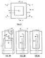
- Figure 7 discloses an embodiment of the invention in which the plastic of the casing, plunger and base form the light guide for the system.
- a plastic base 72 receives the input fibre optic cables 70 and 71. Cable 70 carries the light for the cap indicator illumination, whereas cable 71 carries a signal light beam.
- the rectangular casing 76, base 72 and plunger 78 are moulded from an optical grade acrylic plastic.
- the central rectangular plunger 7 is latched by latch 88 as previously described.
- Cap 80 attached to plunger 78 has transparent coloured indicator sections 86 and 87.
- Figure 7 show the plunger in the "off" position.
- light entering cable 70 passes through collimating lens 90 and strikes angled shoulder 77 which causes the light beam to be internally reflected for the most part at an angle of 90 degrees.
- the light beam proceeds into the centre of clear acrylic plunger 78 and strikes surface 75 which causes the beam to be reflected a second time at a 90 degree angle.
- the plunger in the lower position the beam strikes the cap 80 at a point in the region of coloured section 87 and accordingly illumination indicating "off" status is perceived by the user.
- latch 88 When the switch is in the "on” position, latch 88 allows the plunger, biassed upwardly by spring 44, to move upwardly, and this causes the surface 75 to be moved upwardly within the casing of the switch. Consequently, the light beam is directed to impinge upon transparent coloured section 86 and the user will see a light indicating "on" status.
- Collimating lenses 90 are moulded in the casing or base of the switch to prevent dispersion of the light and allow the switch to operate without separate fibre optic cables which would increase the manufacturing cost of the switch. This factor results in significantly decreased manufacturing costs for the present invention.
- the reflecting surface 25 in the plunger is moulded as an internal reflecting surface in the plunger and needs no mirror surface.
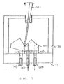
- FIG. 9 A variant of the invention utilizing a toggle switch actuator is shown in Figure 9 in which a toggle switch lever 101 connects at its distal end to a prism light guide 100.
- Input fibre 103 and output fibres 105 and 107 are terminated vertically in a base 72.
- Detentes 102 are used to locate the light guide 100 in each of two positions. In the first position light from input fibre 103 reflects off of guide 100 into output fibre 105 while in a second position it reflects off of guide 100 into output fibre 107.
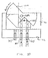
- a rocker switch embodiment of the invention is shown in Figure 10 in which actuator 104 rotates about a pin 109 between each of two positions.
- a light guide 100 is formed directly on the switch and similar to Figure 9 reflects light into either fibre 105 or 107 depending on the rocker position.
- a first slide switch variant is shown in Figure 11 in which a light guide 100 is formed at the bottom of a slide actuator 112 which moves into or out of the paper as shown.
- the two prism reflectors of guide 100 are offset so that when in a first position light is reflected from input fibre 103 to output fibre 105 while in a second position it is reflected into output fibre 107.
- a second slide switch variant shown in Figure 12 is similar to that of Figure 11 except that the slide moves parallel to the paper so as to bring respective reflecting surfaces of light guide 100 into and out of alignment for reflection of light into output fibres 105 and 107, respectively.
- a rotary switch embodiment shown in Figures 13 and 14 includes a knob 118 coupled by a shaft 121 located centrally of switch casing 76 to a rotatable prism light guide 122.
- Multiple detentes 120 located around the shaft 121 locate the light guide 122 at each discrete switch position. At each such position, a plurality of radially spaced apart output fibres 124 are located so as to receive light from input fibre 103 reflected off of prism guide 122.
Landscapes
- Physics & Mathematics (AREA)
- General Physics & Mathematics (AREA)
- Optics & Photonics (AREA)
- Mechanical Light Control Or Optical Switches (AREA)
- Push-Button Switches (AREA)
- Switch Cases, Indication, And Locking (AREA)
Applications Claiming Priority (2)
| Application Number | Priority Date | Filing Date | Title |
|---|---|---|---|
| CA577588 | 1988-09-16 | ||
| CA000577588A CA1282986C (fr) | 1988-09-16 | 1988-09-16 | Commutateur a fibre optique a voyant |
Publications (3)
| Publication Number | Publication Date |
|---|---|
| EP0359712A2 true EP0359712A2 (fr) | 1990-03-21 |
| EP0359712A3 EP0359712A3 (fr) | 1991-10-23 |
| EP0359712B1 EP0359712B1 (fr) | 1997-01-29 |
Family
ID=4138737
Family Applications (1)
| Application Number | Title | Priority Date | Filing Date |
|---|---|---|---|
| EP89810670A Expired - Lifetime EP0359712B1 (fr) | 1988-09-16 | 1989-09-08 | Commutateur à fibres optiques auto-illuminé |
Country Status (4)
| Country | Link |
|---|---|
| US (1) | US5090791A (fr) |
| EP (1) | EP0359712B1 (fr) |
| CA (1) | CA1282986C (fr) |
| DE (1) | DE68927729T2 (fr) |
Cited By (1)
| Publication number | Priority date | Publication date | Assignee | Title |
|---|---|---|---|---|
| GB2285517A (en) * | 1994-01-10 | 1995-07-12 | Labinal | Light signalling optical fibre device for an aircraft |
Families Citing this family (21)
| Publication number | Priority date | Publication date | Assignee | Title |
|---|---|---|---|---|
| US5214727A (en) * | 1992-01-16 | 1993-05-25 | The Trustees Of Princeton University | Electrostatic microactuator |
| US5457757A (en) * | 1992-07-13 | 1995-10-10 | Kidder; John S. | Optical control panel |
| US5410150A (en) * | 1993-01-21 | 1995-04-25 | A. J. Leisure Group Ltd. | Fiber optic controller with an interface having an emitting diode and a photodetector |
| DE4309049C2 (de) * | 1993-03-20 | 1995-04-13 | Marquardt Gmbh | Optisches Schaltelement |
| US5440655A (en) * | 1993-12-29 | 1995-08-08 | At&T Corp. | Optical fiber connector bypass device and method using same |
| US5430261A (en) * | 1994-01-18 | 1995-07-04 | Eaton Corporation | Switch assembly including sequential switch rocker/lever operating mechanism |
| US5481631A (en) * | 1994-02-25 | 1996-01-02 | The Perkin-Elmer Corp. | Optical switching apparatus with retroreflector |
| US5650609A (en) * | 1995-05-15 | 1997-07-22 | Phoenix International Corporation | Seed monitoring system for counting seeds as they are dispensed through a seed planting tube |
| US6091867A (en) * | 1997-05-02 | 2000-07-18 | Neos Technologies, Inc. | M input port by N output port optical switching system |
| US5903687A (en) * | 1997-05-02 | 1999-05-11 | Neos Technologies, Inc. | M input port by N output port optical switching system |
| EP0911578A3 (fr) | 1997-06-02 | 1999-07-28 | Rohm And Haas Company | Dispositif d'éclairage pour fibre optique |
| US6275626B1 (en) * | 1998-10-26 | 2001-08-14 | Herzel Laor | 1xN reflector switch |
| US6740864B1 (en) * | 2002-04-30 | 2004-05-25 | Finisar Corporation | Method and apparatus for monitoring optical switches and cross-connects |
| TWI240160B (en) * | 2004-01-29 | 2005-09-21 | Asustek Comp Inc | Electronic device with light-passed board |
| WO2006116468A2 (fr) * | 2005-04-25 | 2006-11-02 | Sensata Technologies, Inc.; Power Control Business Unit | Dispositif et procede de commutation |
| US7928859B1 (en) | 2008-11-21 | 2011-04-19 | Yazaki North America, Inc. | Full angle laser illuminate instrument cluster |
| US7954965B1 (en) | 2009-04-13 | 2011-06-07 | Yazaki North America, Inc. | Method for multiple gauges in a scanning laser based display device |
| US8026827B1 (en) | 2009-05-04 | 2011-09-27 | Yazaki North America, Inc. | Virtual push button switch |
| DE102009051617B3 (de) * | 2009-11-02 | 2011-04-28 | Pas Deutschland Gmbh | Taste für eine Bedienanordnung, sowie Bedienanordnung und Haushaltsgerät |
| US10237710B2 (en) | 2015-09-28 | 2019-03-19 | Eaton Intelligent Power Limited | Control system with smart devices for hazardous environments |
| WO2022029851A1 (fr) * | 2020-08-03 | 2022-02-10 | 日本電信電話株式会社 | Commutateur optique |
Family Cites Families (11)
| Publication number | Priority date | Publication date | Assignee | Title |
|---|---|---|---|---|
| US3999074A (en) * | 1973-08-02 | 1976-12-21 | Callaghan James M | Fiber-optic photoelectric power control device |
| JPS5574503A (en) * | 1978-11-29 | 1980-06-05 | Nec Corp | Mechanical photo switch |
| US4315147A (en) * | 1980-02-15 | 1982-02-09 | Battelle Memorial Institute | Photoelectric switch with visible signal |
| US4378144A (en) * | 1980-12-22 | 1983-03-29 | Northern Telecom Limited | Optical switch |
| JPS57139704A (en) * | 1981-02-24 | 1982-08-28 | Nippon Sheet Glass Co Ltd | Optical switch |
| US4569569A (en) * | 1982-03-31 | 1986-02-11 | Plessey Overseas Limited | Optical coupling devices |
| DE3439905A1 (de) * | 1984-10-31 | 1986-04-30 | Siemens AG, 1000 Berlin und 8000 München | Drehschalter fuer lichtwellenleiter |
| US4726646A (en) * | 1985-02-20 | 1988-02-23 | E. I. Du Pont De Nemours And Company | Optical switch |
| FR2581204B1 (fr) * | 1985-04-29 | 1988-08-26 | Thomson Csf Mat Tel | Selecteur optique 1 par n a commande mecanique, pour fibres multimodes |
| US4789215A (en) * | 1986-04-18 | 1988-12-06 | Northern Telecom Limited | Fiber optic switch with prism mounted for reciprocal and rotational movement |
| US4704656A (en) * | 1986-10-27 | 1987-11-03 | Leviton Manufacturing Company, Inc. | Fiber optic wiring device control system |
-
1988
- 1988-09-16 CA CA000577588A patent/CA1282986C/fr not_active Expired
-
1989
- 1989-09-06 US US07/403,373 patent/US5090791A/en not_active Expired - Fee Related
- 1989-09-08 DE DE68927729T patent/DE68927729T2/de not_active Expired - Fee Related
- 1989-09-08 EP EP89810670A patent/EP0359712B1/fr not_active Expired - Lifetime
Cited By (1)
| Publication number | Priority date | Publication date | Assignee | Title |
|---|---|---|---|---|
| GB2285517A (en) * | 1994-01-10 | 1995-07-12 | Labinal | Light signalling optical fibre device for an aircraft |
Also Published As
| Publication number | Publication date |
|---|---|
| EP0359712A3 (fr) | 1991-10-23 |
| DE68927729D1 (de) | 1997-03-13 |
| DE68927729T2 (de) | 1997-07-17 |
| US5090791A (en) | 1992-02-25 |
| EP0359712B1 (fr) | 1997-01-29 |
| CA1282986C (fr) | 1991-04-16 |
Similar Documents
| Publication | Publication Date | Title |
|---|---|---|
| US5090791A (en) | Self-illuminated fibre optic switch | |
| EP0506847B1 (fr) | Contact fibroptique a reflecteur spherique | |
| US4261638A (en) | Optical switch with rotating, reflective, concave surface | |
| CA1076675A (fr) | Systeme de commande a fonctions multiples, a fibres optiques, pour vehicules | |
| EP0151022B1 (fr) | Dispositif manuel d'entrée pour la fourniture des entrées à un dispositif pour le traitement informatique | |
| US6111563A (en) | Cordless retroreflective optical computer mouse | |
| US3157771A (en) | Lighted push button switch assembly | |
| WO2001023805A1 (fr) | Illuminateur dote d'une interface utilisateur | |
| JPS5831562B2 (ja) | 光学フアイバ用光学スイツチ | |
| CN209000030U (zh) | 光学操作模块及具有指纹辨识装置的光学操作模块 | |
| TW201633343A (zh) | 光電一體式機械軸鍵盤開關模組 | |
| US4437728A (en) | Photo-switch | |
| CN105742098A (zh) | 一种光电式线性控制的键盘按键开关 | |
| US4899260A (en) | Optical conductor body for illuminating indication elements of electrical apparatuses | |
| US5883994A (en) | Light dissipating spring interconnection between lightguides | |
| US5986792A (en) | Lighting system sequencer and method | |
| WO1989009515A1 (fr) | Interrupteur a poussoir electronique | |
| CN208237770U (zh) | 一种发光装置和车灯 | |
| EP0422685B1 (fr) | Commutateur photo-électrique | |
| US6665465B2 (en) | Optical switch | |
| JPH08241658A (ja) | 光検知型スイッチ | |
| JP2645140B2 (ja) | 電磁接触器の動作表示装置 | |
| TW494252B (en) | An optical switch with movable mirror mechanism | |
| US20020085799A1 (en) | Optical switch | |
| SU726666A1 (ru) | Бесконтактный переключатель с механическим приводом |
Legal Events
| Date | Code | Title | Description |
|---|---|---|---|
| PUAI | Public reference made under article 153(3) epc to a published international application that has entered the european phase |
Free format text: ORIGINAL CODE: 0009012 |
|
| AK | Designated contracting states |
Kind code of ref document: A2 Designated state(s): DE FR GB IT |
|
| PUAL | Search report despatched |
Free format text: ORIGINAL CODE: 0009013 |
|
| AK | Designated contracting states |
Kind code of ref document: A3 Designated state(s): DE FR GB IT |
|
| 17P | Request for examination filed |
Effective date: 19920630 |
|
| 17Q | First examination report despatched |
Effective date: 19940425 |
|
| GRAG | Despatch of communication of intention to grant |
Free format text: ORIGINAL CODE: EPIDOS AGRA |
|
| GRAH | Despatch of communication of intention to grant a patent |
Free format text: ORIGINAL CODE: EPIDOS IGRA |
|
| GRAH | Despatch of communication of intention to grant a patent |
Free format text: ORIGINAL CODE: EPIDOS IGRA |
|
| GRAA | (expected) grant |
Free format text: ORIGINAL CODE: 0009210 |
|
| AK | Designated contracting states |
Kind code of ref document: B1 Designated state(s): DE FR GB IT |
|
| PG25 | Lapsed in a contracting state [announced via postgrant information from national office to epo] |
Ref country code: IT Free format text: LAPSE BECAUSE OF FAILURE TO SUBMIT A TRANSLATION OF THE DESCRIPTION OR TO PAY THE FEE WITHIN THE PRE;WARNING: LAPSES OF ITALIAN PATENTS WITH EFFECTIVE DATE BEFORE 2007 MAY HAVE OCCURRED AT ANY TIME BEFORE 2007. THE CORRECT EFFECTIVE DATE MAY BE DIFFERENT FROM THE ONE RECORDED.SCRIBED TIME-LIMIT Effective date: 19970129 |
|
| REF | Corresponds to: |
Ref document number: 68927729 Country of ref document: DE Date of ref document: 19970313 |
|
| ET | Fr: translation filed | ||
| PLBE | No opposition filed within time limit |
Free format text: ORIGINAL CODE: 0009261 |
|
| STAA | Information on the status of an ep patent application or granted ep patent |
Free format text: STATUS: NO OPPOSITION FILED WITHIN TIME LIMIT |
|
| 26N | No opposition filed | ||
| PGFP | Annual fee paid to national office [announced via postgrant information from national office to epo] |
Ref country code: GB Payment date: 20000905 Year of fee payment: 12 |
|
| PGFP | Annual fee paid to national office [announced via postgrant information from national office to epo] |
Ref country code: DE Payment date: 20000923 Year of fee payment: 12 |
|
| PGFP | Annual fee paid to national office [announced via postgrant information from national office to epo] |
Ref country code: FR Payment date: 20000929 Year of fee payment: 12 |
|
| PG25 | Lapsed in a contracting state [announced via postgrant information from national office to epo] |
Ref country code: GB Free format text: LAPSE BECAUSE OF NON-PAYMENT OF DUE FEES Effective date: 20010908 |
|
| GBPC | Gb: european patent ceased through non-payment of renewal fee |
Effective date: 20010908 |
|
| PG25 | Lapsed in a contracting state [announced via postgrant information from national office to epo] |
Ref country code: DE Free format text: LAPSE BECAUSE OF NON-PAYMENT OF DUE FEES Effective date: 20020501 |
|
| PG25 | Lapsed in a contracting state [announced via postgrant information from national office to epo] |
Ref country code: FR Free format text: LAPSE BECAUSE OF NON-PAYMENT OF DUE FEES Effective date: 20020531 |
|
| REG | Reference to a national code |
Ref country code: FR Ref legal event code: ST |