EP0359728B1 - Dispositif de verrouillage pour porte de machine à laver, essoreuse ou similaire - Google Patents
Dispositif de verrouillage pour porte de machine à laver, essoreuse ou similaire Download PDFInfo
- Publication number
- EP0359728B1 EP0359728B1 EP89850271A EP89850271A EP0359728B1 EP 0359728 B1 EP0359728 B1 EP 0359728B1 EP 89850271 A EP89850271 A EP 89850271A EP 89850271 A EP89850271 A EP 89850271A EP 0359728 B1 EP0359728 B1 EP 0359728B1
- Authority
- EP
- European Patent Office
- Prior art keywords
- blocking
- locking
- plate
- catch member
- blocking means
- Prior art date
- Legal status (The legal status is an assumption and is not a legal conclusion. Google has not performed a legal analysis and makes no representation as to the accuracy of the status listed.)
- Expired - Lifetime
Links
- 238000005406 washing Methods 0.000 title claims description 12
- 230000000903 blocking effect Effects 0.000 claims description 65
- 239000012858 resilient material Substances 0.000 claims description 2
- 230000004913 activation Effects 0.000 claims 1
- 238000010438 heat treatment Methods 0.000 description 2
- 238000010420 art technique Methods 0.000 description 1
- 230000005284 excitation Effects 0.000 description 1
- 230000002779 inactivation Effects 0.000 description 1
- 238000004519 manufacturing process Methods 0.000 description 1
- 239000002184 metal Substances 0.000 description 1
- 238000000034 method Methods 0.000 description 1
- 230000000717 retained effect Effects 0.000 description 1
- 238000004804 winding Methods 0.000 description 1
Images

Classifications
-
- D—TEXTILES; PAPER
- D06—TREATMENT OF TEXTILES OR THE LIKE; LAUNDERING; FLEXIBLE MATERIALS NOT OTHERWISE PROVIDED FOR
- D06F—LAUNDERING, DRYING, IRONING, PRESSING OR FOLDING TEXTILE ARTICLES
- D06F37/00—Details specific to washing machines covered by groups D06F21/00 - D06F25/00
- D06F37/42—Safety arrangements, e.g. for stopping rotation of the receptacle upon opening of the casing door
-
- D—TEXTILES; PAPER
- D06—TREATMENT OF TEXTILES OR THE LIKE; LAUNDERING; FLEXIBLE MATERIALS NOT OTHERWISE PROVIDED FOR
- D06F—LAUNDERING, DRYING, IRONING, PRESSING OR FOLDING TEXTILE ARTICLES
- D06F39/00—Details of washing machines not specific to a single type of machines covered by groups D06F9/00 - D06F27/00
- D06F39/12—Casings; Tubs
- D06F39/14—Doors or covers; Securing means therefor
-
- Y—GENERAL TAGGING OF NEW TECHNOLOGICAL DEVELOPMENTS; GENERAL TAGGING OF CROSS-SECTIONAL TECHNOLOGIES SPANNING OVER SEVERAL SECTIONS OF THE IPC; TECHNICAL SUBJECTS COVERED BY FORMER USPC CROSS-REFERENCE ART COLLECTIONS [XRACs] AND DIGESTS
- Y10—TECHNICAL SUBJECTS COVERED BY FORMER USPC
- Y10S—TECHNICAL SUBJECTS COVERED BY FORMER USPC CROSS-REFERENCE ART COLLECTIONS [XRACs] AND DIGESTS
- Y10S292/00—Closure fasteners
- Y10S292/69—Washing machine or stove closure latch
-
- Y—GENERAL TAGGING OF NEW TECHNOLOGICAL DEVELOPMENTS; GENERAL TAGGING OF CROSS-SECTIONAL TECHNOLOGIES SPANNING OVER SEVERAL SECTIONS OF THE IPC; TECHNICAL SUBJECTS COVERED BY FORMER USPC CROSS-REFERENCE ART COLLECTIONS [XRACs] AND DIGESTS
- Y10—TECHNICAL SUBJECTS COVERED BY FORMER USPC
- Y10T—TECHNICAL SUBJECTS COVERED BY FORMER US CLASSIFICATION
- Y10T292/00—Closure fasteners
- Y10T292/08—Bolts
- Y10T292/0911—Hooked end
- Y10T292/0945—Operating means
- Y10T292/0951—Rigid
- Y10T292/0959—Swinging catch
-
- Y—GENERAL TAGGING OF NEW TECHNOLOGICAL DEVELOPMENTS; GENERAL TAGGING OF CROSS-SECTIONAL TECHNOLOGIES SPANNING OVER SEVERAL SECTIONS OF THE IPC; TECHNICAL SUBJECTS COVERED BY FORMER USPC CROSS-REFERENCE ART COLLECTIONS [XRACs] AND DIGESTS
- Y10—TECHNICAL SUBJECTS COVERED BY FORMER USPC
- Y10T—TECHNICAL SUBJECTS COVERED BY FORMER US CLASSIFICATION
- Y10T292/00—Closure fasteners
- Y10T292/175—Bolt releasers
- Y10T292/18—Free-end-engaging means
-
- Y—GENERAL TAGGING OF NEW TECHNOLOGICAL DEVELOPMENTS; GENERAL TAGGING OF CROSS-SECTIONAL TECHNOLOGIES SPANNING OVER SEVERAL SECTIONS OF THE IPC; TECHNICAL SUBJECTS COVERED BY FORMER USPC CROSS-REFERENCE ART COLLECTIONS [XRACs] AND DIGESTS
- Y10—TECHNICAL SUBJECTS COVERED BY FORMER USPC
- Y10T—TECHNICAL SUBJECTS COVERED BY FORMER US CLASSIFICATION
- Y10T292/00—Closure fasteners
- Y10T292/68—Keepers
- Y10T292/696—With movable dog, catch or striker
- Y10T292/702—Pivoted or swinging
Definitions
- the present invention refers to a locking device in a door of a washing machine, a spin dryer or the like according to the preamble of the following claim 1.
- the purpose of the locking device is to prevent opening of the door until the drum has stopped.
- a desire for the possibility of opening the door even in case of power failure can be met with by using a bimetal lock wherein a bimetal operated catch member is kept in a blocking position by an electric current heating the bimetal. In case of power failure the heating current will cease and the catch member will move from the blocking position to a lock releasing position.
- bimetal locks are sensitive to temperature which causes a great variation in the time of change from the blocking to the releasing position.
- the time to lapse before the door of the machine can be opened has to be chosen so long that in any case the drum has stopped before opening can take place.
- the drum stopping time varies with the amount of laundry and also depends on whether the machine is new or old (the drum rotates more easily in an old machine).
- DE-A-2 017 664 discloses a locking device for a door in a washing machine in which a pivotable locking member is disposed in the machine and cooperates with a catch member disposed on the door of said machine. Upon closing of the door the catch member operates on the locking member turning it to its locking position. During the turning movement the locking member displaces an elongate plate member from a lock releasing position into a locking position in which said plate member is retained by means which can be operated into a plate releasing position upon actuation of a solenoid device.
- EP-A-0 007 637 discloses a locking device for a door in a washing machine in which a locking member can be operated to take either of two stable positions, namely a locking position and a lock releasing position, respectively.
- a driving device is provided which is operated by pulses from a microprocessor or the like to act so as to bring the locking member to the lock releasing position when said member is in the locking position and, alternatively, to bring the locking member to the locking position when said member is in the lock releasing position.
- Another object is to simplify the known device having two separate operating means and, hence, to reduce the costs of manufacture.
- a third object is to make possible the use of a swingable blocking means including a plate, wherein the angular position of engagement of the blocking means with the catch member for preventing movement of same differs from the angular position of the plate which constitutes the blocking position of the blocking means.
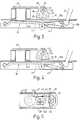
- the door lock is built-up on a base 10 which by means, not shown, is secured adjacent to the loading opening of a washing machine, not shown.
- the base is provided with a locking plate 10a having an opening 11 through which a catch 12 can be inserted.
- the catch is pivotably journalled on a door, not shown, closing the loading opening.
- spring means the catch is biased to the position shown in Fig. 2 where an edge 13 on the catch falls in behind an edge 14 bounding the opening 11.
- a blocking plate 15 is provided with an opening 16 which, as shown in Fig. 2, surrounds a part 12a of the catch 12 inserted through the opening 11.
- An edge 44 bounding the opening 16 of the blocking plate bears on the part 12a of the catch 12 preventing it from moving away from the locking position.
- the blocking plate 15 is fixedly secured to a plate 17 acting as a support for plate 15. The two plates are so interconnected that the blocking plate is given the shape of a V the legs of which are directed towards the locking plate 10a.
- the opposite end of the blocking plate forms with the plate 17 a journalling sleeve 18 by which the unit 19 formed by the blocking plate 15 and the support plate 17 is pivotably journalled on a pin 20 fixed to the base 10.
- a spring 21, Fig. 5 the unit 19 is biased to the position shown in Fig. 3, which is the lock releasing position of the blocking plate.
- an electromagnet 22 is provided which has an excitation winding 23 connected to a control device, not shown.
- the control device co-operates with a programmer provided for the control of the washing machine.
- the electromagnet 22 is acting as a pulling magnet attracting when activated the unit 19 which forms the movable armature of the magnet.
- Fig. 2 shows this condition which appears when the catch 12 is to be blocked and when it is to be released as well.
- the electromagnet co-operates with a separate mechanism 24 in order to keep the blocking plate in the blocking position (Fig. 3) and in the lock releasing position (Fig. 1), respectively.
- the mechanism comprises a wire bow 25 which is turnably journalled by a part 25a entering a journalling hole in a sheet metal bracket 26.
- the opposite end 25b of the wire bow co-operates with a guiding track 27 provided in a guide plate 28.
- the guiding track comprises two rest positions 29, 30 corresponding to the blocking position, Fig. 3, of the blocking plate 15 and to the lock releasing position, Fig. 1, thereof (see also Fig. 2).
- the guiding track also comprises two temporary rest positions 31, 32 which are disposed between the rest positions 29, 30. With the opposite end 25b taking any of the said temporary rest positions 31, 32 the unit 19 is permitted to move to a position wherein the blocking plate 15 bears on the locking plate 10a.
- the guiding track extends inwards into the plane of the paper and has a bottom part provided with steps 33, 34, 35, 36 of a design placing the different rest positions in different planes in the depth direction of the track.
- the end 25b of the wire bow extends perpendicular to the plane of the paper towards the bottom of the track against which it is biased by a spring 45.
- the plate 17 has taken a position between the position shown in Fig. 2 and the position shown in Fig. 1.
- the blocking plate is made of resilient material permitting movement of the unit 19 to the position shown in Figs. 2 and 4.
- the steps 33, 34, 35, 36 are situated in different planes such that in the order indicated each step at the border to the following step is disposed at a higher level than said following step. Accordingly, when the magnet 22 is activated and the wire bow is in the rest position 30 the wire bow will be moved along the step 33 and part of step 34 to the temporary rest position 31. Then, when the magnet is inactivated the wire bow is moved via steps 34 and 35 to the rest position 29 where it remains.
- Figs. 2 and 3 where Fig. 2 shows the positions of the wire bow and the unit 19, respectively, when, starting from the position shown in Fig. 1 with a catch taking its locking position (Fig. 2), the magnet 22 has been activated.
- Fig. 2 shows the positions of the wire bow and the unit 19, respectively, when, starting from the position shown in Fig. 1 with a catch taking its locking position (Fig. 2), the magnet 22 has been activated.
- Fig. 2 shows the positions of the wire bow and the unit 19, respectively, when, starting from the position shown in
- step 3 there are shown the positions of the wire bow and the unit 19 with the blocking plate 15, respectively, when the magnet has been inactivated.
- the blocking plate has taken its blocking position.
- the wire bow 25 is moved via step 35 and part of step 36 to the temporary rest position 32 and upon the following inactivation of the magnet the wire bow will be guided via step 36 and part of step 33 back to the rest position 30 causing the unit 19 to take the position shown in Fig. 1 and the blocking plate to take its lock releasing position.
- a blocking device is provided in the shape of a wire bow 39 journalled in two side parts 37, 38 of the base 10.
- the wire bow 39 has two parts 40, 41 which are oppositely disposed with respect to the journalling axis.
- the part 41 is biased in a clockwise direction by a spring 42, see Figs. 1-4.
Landscapes
- Engineering & Computer Science (AREA)
- Textile Engineering (AREA)
- Main Body Construction Of Washing Machines And Laundry Dryers (AREA)
Claims (4)
- Dispositif de verrouillage pour une porte de lavelinge, d'essoreuse ou de machine similaire, comprenant un panneau de verrouillage (10a) situé sur la machine et percé d'un premier orifice (11), et un loquet (12) situé sur la porte pour pouvoir être inséré dans ledit premier orifice, le loquet venant en prise, dans une position de verrouillage, avec une arête (14) délimitant le premier orifice (11), afin de maintenir la porte fermée, un moyen de blocage (19) actionnable électriquement étant prévu pour empêcher le loquet (12) de se déplacer à l'écart de la position de verrouillage tant qu'un tambour rotatif ou élément similaire, logé dans la machine, est en fonction, des moyens de libération (22, 24, 25) étant prévus pour libérer le moyen de blocage (19) dès que le mouvement rotatoire a cessé, et un moyen d'entraînement électrique (22) étant prévu pour amener le moyen de blocage (19) à une position de blocage, en s'opposant à l'action d'un moyen de sollicitation (21) ayant tendance à amener le moyen de blocage (19) à une position de déverrouillage, le moyen d'entraînement électrique (22) coopérant avec un mécanisme (24) conçu de telle sorte que, lors d'une activation du moyen d'entraînement (22), le moyen de blocage (19) soit manoeuvré pour prendre en alternance, respectivement, la position de blocage et la position de déverrouillage, le moyen d'entraînement (22) étant un électro-aimant dont l'induit mobile est constitué par le moyen de blocage (19) dont une partie (15) est percée d'un second orifice (16), ladite partie entourant le loquet (12) dans la position de blocage du moyen de blocage (19), une arête (44), délimitant le second orifice (16), ayant pour effet de bloquer le loquet (12) dans sa position de verrouillage, caractérisé par le fait que le moyen de blocage (19) comprend une plaque (17) qui est montée à pivotement et qui, lorsque l'électro-aimant (22) est activé, prend une position dans laquelle elle s'étend pour l'essentiel parallèlement au panneau de verrouillage (10a), la partie du moyen de blocage (19) qui est percée du second orifice (16) étant formée par une plaque de blocage (15) fabriquée en un matériau élastique, et étant fixée à la plaque pivotante (17) de façon telle que, dans la position de blocage du moyen de blocage (19), la plaque de blocage (15) revête la forme d'un V dont les branches sont tournées vers le panneau de verrouillage (10a).
- Dispositif de verrouillage selon la revendication 1, caractérisé par le fait que le mécanisme (24) coopérant avec le moyen d'entraînement (22) comprend un étrier (25) en fil métallique ou un organe analogue, fixé de façon mobile à la plaque pivotante (17) et dont l'une (25b) des extrémités coopère avec une piste de guidage (27) comprenant deux positions de repos (29, 30) correspondant, respectivement, à la position de blocage et à la position de déverrouillage du moyen de blocage (19), et deux positions de repos provisoire (31, 32) situées entre lesdites positions de repos (29, 30), l'étrier (25) en fil métallique prenant alternativement l'une (31) ou l'autre (32) des positions de repos provisoire lorsque, l'électro-aimant étant activé, la plaque pivotante (17) du moyen de blocage (19), pressant la plaque de blocage (15), prend la position dans laquelle elle s'étend parallèlement au panneau de verrouillage (10a).
- Plaque de verrouillage selon l'une quelconque des revendications précédentes, caractérisée par le fait qu'un dispositif de blocage (39, 40, 41 ; 43) est prévu pour empêcher le dispositif de blocage (19) de se déplacer jusqu'à la position de blocage au cas où le loquet (12) n'a pas pris la position de verrouillage.
- Dispositif de verrouillage selon la revendication 3, caractérisé par le fait que le dispositif de blocage comprend un étrier (39) en fil métallique, monté à pivotement dans la machine et comprenant deux parties (40, 41) qui sont disposées de part et d'autre de l'axe de basculement, et forment des leviers, l'une (40) desdites parties coopérant avec le loquet (12) et l'autre partie coopérant avec une butée (43) prévue sur le moyen de blocage (19), ledit dispositif de blocage (39, 40, 41) coopérant avec la butée (43), lorsqu'il occupe sa position de blocage, afin d'empêcher le moyen de blocage (19) de se déplacer à sa position de blocage alors que le loquet (12), prenant sa position de verrouillage, vient en prise avec l'étrier (39) en fil métallique pour le faire tourner vers une position propre à autoriser ledit mouvement du moyen de blocage (19).
Applications Claiming Priority (2)
| Application Number | Priority Date | Filing Date | Title |
|---|---|---|---|
| SE8803289 | 1988-09-16 | ||
| SE8803289A SE461989B (sv) | 1988-09-16 | 1988-09-16 | Laasanordning foer en lucka till en tvaettmaskin, centrifug e d |
Publications (3)
| Publication Number | Publication Date |
|---|---|
| EP0359728A2 EP0359728A2 (fr) | 1990-03-21 |
| EP0359728A3 EP0359728A3 (en) | 1990-08-08 |
| EP0359728B1 true EP0359728B1 (fr) | 1994-05-18 |
Family
ID=20373362
Family Applications (1)
| Application Number | Title | Priority Date | Filing Date |
|---|---|---|---|
| EP89850271A Expired - Lifetime EP0359728B1 (fr) | 1988-09-16 | 1989-08-25 | Dispositif de verrouillage pour porte de machine à laver, essoreuse ou similaire |
Country Status (4)
| Country | Link |
|---|---|
| US (1) | US4932707A (fr) |
| EP (1) | EP0359728B1 (fr) |
| DE (1) | DE68915373T2 (fr) |
| SE (1) | SE461989B (fr) |
Families Citing this family (29)
| Publication number | Priority date | Publication date | Assignee | Title |
|---|---|---|---|---|
| US5004276A (en) * | 1990-01-22 | 1991-04-02 | The Stanley Works | Push to close latch for self-cleaning oven |
| US5072974A (en) * | 1991-02-07 | 1991-12-17 | The Stanley Works | Push to close latch for self-cleaning oven |
| US5174618A (en) * | 1991-12-09 | 1992-12-29 | Maytag Corporation | Door latch assembly |
| US5401067A (en) * | 1992-06-10 | 1995-03-28 | Nifco, Inc. | Latch device |
| KR0122137Y1 (ko) * | 1993-09-21 | 1998-10-01 | 김광호 | 세탁기 도어 개폐장치 |
| ES2081760B1 (es) * | 1993-11-15 | 1998-11-01 | Anell Ramon Baraut | Perfeccionamientos en las maquinas para el centrifugado de alfombras. |
| DE19549197A1 (de) * | 1995-08-04 | 1997-02-06 | Ellenberger & Poensgen | Elektrische Bearbeitungsmaschine, insbesondere Wasch- oder Trockenmaschine |
| US6048001A (en) * | 1997-03-31 | 2000-04-11 | Miller; Seth A. | Push-button actuated latching mechanism |
| IT1296669B1 (it) * | 1997-12-22 | 1999-07-14 | Bitron Spa | Dispositivo di bloccaggio e sbloccaggio di un portello di un apparecchio elettrodomestico. |
| US6036241A (en) * | 1998-03-11 | 2000-03-14 | Maytag Corporation | Locking mechanism for an appliance door |
| ITTO980511A1 (it) * | 1998-06-11 | 1999-12-13 | Bitron Spa | Dispositivo di bloccaggio di un portello di un apparecchio elettrodome stico. |
| US6363755B1 (en) * | 1999-12-07 | 2002-04-02 | Ark-Les Corporation | Timed release washing machine lid lock |
| DE10038376C2 (de) * | 2000-08-07 | 2003-04-30 | Zangenstein Elektro | Türverriegelung für die Tür eines elektrischen Haushaltsgerätes |
| EP1217117B1 (fr) * | 2000-12-22 | 2005-03-02 | Elektromanufaktur Zangenstein, Hanauer GmbH & Co. KGaA | Dispositif pour verrouiller et déverrouiller une serrure de porte d'un appareil électrique |
| US6679572B2 (en) | 2001-02-14 | 2004-01-20 | Maytag Corporation | Lid or door for household appliances |
| TW513548B (en) * | 2001-05-08 | 2002-12-11 | Mosel Vitelic Inc | Cover sensing system of spin dryer |
| US7492273B2 (en) | 2003-03-10 | 2009-02-17 | Walter Kidde Portable Equipment, Inc. | Pivoting battery carrier and a life safety device incorporating the same |
| US7900979B2 (en) * | 2003-06-27 | 2011-03-08 | Illinois Tool Works, Inc. | Low power consumption lock for appliance latch |
| EP1740752B1 (fr) | 2004-04-27 | 2013-03-27 | Marquardt GmbH | Verrou pour appareil menager |
| ITTO20050333A1 (it) * | 2005-05-17 | 2006-11-18 | Itw Ind Components Srl | Dispositivo bloccaporta per un elettrodomestico, in particolare un forno pirolitico |
| US7858307B2 (en) * | 2005-08-09 | 2010-12-28 | Maxwell Sensors, Inc. | Light transmitted assay beads |
| US7390045B2 (en) * | 2006-06-15 | 2008-06-24 | International Automotive Components Group North America, Inc. | System for attaching an article holding assembly to a mounting member in a vehicle |
| US8246089B2 (en) * | 2006-10-28 | 2012-08-21 | Marquardt Gmbh | Lock for a household appliance |
| ITTO20070476A1 (it) * | 2007-06-29 | 2008-12-30 | Itw Metalflex Druzba Za Proizv | Dispositivo elettromagnetico di bloccaggio per una porta di un elettrodomestico, in particolare un oblo' di una lavatrice |
| PL2278058T3 (pl) * | 2009-07-17 | 2016-09-30 | Urządzenie do blokowania drzwi otworu załadunkowego pralek i suszarek | |
| CN103233634B (zh) | 2012-01-18 | 2016-11-02 | 伊利诺斯工具制品有限公司 | 锁装置和安装锁装置的设备 |
| DE102019005564B3 (de) * | 2019-05-10 | 2020-09-17 | Emz-Hanauer Gmbh & Co. Kgaa | Türverschluss für ein elektrisches Haushaltsgerät |
| CN115247350B (zh) * | 2021-04-27 | 2026-04-21 | 青岛海尔滚筒洗衣机有限公司 | 一种门锁装置及洗衣机 |
| WO2023122814A1 (fr) * | 2021-12-30 | 2023-07-06 | STIWA Advanced Products GmbH | Dispositif actionneur doté d'un élément de rappel |
Family Cites Families (6)
| Publication number | Priority date | Publication date | Assignee | Title |
|---|---|---|---|---|
| DE2017664A1 (de) * | 1970-04-14 | 1971-10-28 | Trumpf Schloss U Beschlagfabri | Elektromagnetisch entriegelbarer Verschluß für Waschautomaten od.dgl |
| DE2163449A1 (de) * | 1971-12-21 | 1973-07-05 | Miele & Cie | Tuerverriegelung fuer eine wasch- oder schleudermaschine |
| IT994158B (it) * | 1973-08-21 | 1975-10-20 | Texas Instruments Italia Spa | Dispositivo di bloccaggio con interruttore ritardatore termico ad azionamento voltmetrico per sportelli |
| DE2833860A1 (de) * | 1978-08-02 | 1980-02-21 | Ellenberger & Poensgen | Bistabile verriegelungsvorrichtung fuer waschmaschinentueren |
| US4702506A (en) * | 1984-06-29 | 1987-10-27 | Kyosuke Iimura | Magnet catcher for doors |
| US4776620A (en) * | 1986-09-29 | 1988-10-11 | Whirlpool Corporation | Door latch for dishwasher |
-
1988
- 1988-09-16 SE SE8803289A patent/SE461989B/sv not_active IP Right Cessation
-
1989
- 1989-08-01 US US07/388,154 patent/US4932707A/en not_active Expired - Fee Related
- 1989-08-25 EP EP89850271A patent/EP0359728B1/fr not_active Expired - Lifetime
- 1989-08-25 DE DE68915373T patent/DE68915373T2/de not_active Expired - Fee Related
Also Published As
| Publication number | Publication date |
|---|---|
| DE68915373T2 (de) | 1994-10-20 |
| EP0359728A3 (en) | 1990-08-08 |
| SE8803289D0 (sv) | 1988-09-16 |
| SE8803289L (fr) | 1990-03-17 |
| DE68915373D1 (de) | 1994-06-23 |
| EP0359728A2 (fr) | 1990-03-21 |
| SE461989B (sv) | 1990-04-23 |
| US4932707A (en) | 1990-06-12 |
Similar Documents
| Publication | Publication Date | Title |
|---|---|---|
| US4932707A (en) | Locking device for a door of a washing machine, a spin dryer or the like | |
| US3910617A (en) | Solenoid operated electric strike | |
| US4623179A (en) | Door latch for appliance | |
| JPH0220123B2 (fr) | ||
| EP0085296B1 (fr) | Système de serrure | |
| JPH0365468B2 (fr) | ||
| EP0588041B1 (fr) | Arrangement de verrouillage de porte pour machines à laver | |
| EP0965677B1 (fr) | Dispositif de fermeture de porte pour un appareil électro-ménager | |
| US4342476A (en) | Electromechanical lid latch assembly | |
| US4012063A (en) | Interlock latch assembly for centrifugals | |
| JP3967600B2 (ja) | 洗濯機の蓋ロック装置 | |
| JPS604446B2 (ja) | 写真カメラの露出制御装置 | |
| NO319453B1 (no) | Sikringsinnretning for en vender i en dorapner | |
| JPH1088945A (ja) | 電動シャッタ−用開閉機の手動操作装置 | |
| JPH0110693Y2 (fr) | ||
| JP3726300B2 (ja) | 自動販売機の施錠装置 | |
| JPH0342526Y2 (fr) | ||
| JP3756962B2 (ja) | 扉付き遊戯機 | |
| JPH1161752A (ja) | 電動遮断機及び停電時の電動遮断機によるトラブル防止方法 | |
| JPH03124477A (ja) | リボンカセット | |
| JPH0240693Y2 (fr) | ||
| JP3623291B2 (ja) | 電動シャッタ | |
| JPH1144379A (ja) | バルブの緊急遮断用アクチュエータ | |
| JPH0896670A (ja) | 遮断器の操作装置 | |
| JPH0530221Y2 (fr) |
Legal Events
| Date | Code | Title | Description |
|---|---|---|---|
| PUAI | Public reference made under article 153(3) epc to a published international application that has entered the european phase |
Free format text: ORIGINAL CODE: 0009012 |
|
| AK | Designated contracting states |
Kind code of ref document: A2 Designated state(s): DE GB IT |
|
| PUAL | Search report despatched |
Free format text: ORIGINAL CODE: 0009013 |
|
| AK | Designated contracting states |
Kind code of ref document: A3 Designated state(s): DE GB IT |
|
| 17P | Request for examination filed |
Effective date: 19910126 |
|
| 17Q | First examination report despatched |
Effective date: 19920917 |
|
| GRAA | (expected) grant |
Free format text: ORIGINAL CODE: 0009210 |
|
| AK | Designated contracting states |
Kind code of ref document: B1 Designated state(s): DE GB IT |
|
| REF | Corresponds to: |
Ref document number: 68915373 Country of ref document: DE Date of ref document: 19940623 |
|
| ITF | It: translation for a ep patent filed | ||
| PLBE | No opposition filed within time limit |
Free format text: ORIGINAL CODE: 0009261 |
|
| STAA | Information on the status of an ep patent application or granted ep patent |
Free format text: STATUS: NO OPPOSITION FILED WITHIN TIME LIMIT |
|
| 26N | No opposition filed | ||
| PGFP | Annual fee paid to national office [announced via postgrant information from national office to epo] |
Ref country code: GB Payment date: 19970818 Year of fee payment: 9 |
|
| PGFP | Annual fee paid to national office [announced via postgrant information from national office to epo] |
Ref country code: DE Payment date: 19970901 Year of fee payment: 9 |
|
| PG25 | Lapsed in a contracting state [announced via postgrant information from national office to epo] |
Ref country code: GB Free format text: LAPSE BECAUSE OF NON-PAYMENT OF DUE FEES Effective date: 19980825 |
|
| GBPC | Gb: european patent ceased through non-payment of renewal fee |
Effective date: 19980825 |
|
| PG25 | Lapsed in a contracting state [announced via postgrant information from national office to epo] |
Ref country code: DE Free format text: LAPSE BECAUSE OF NON-PAYMENT OF DUE FEES Effective date: 19990601 |
|
| PG25 | Lapsed in a contracting state [announced via postgrant information from national office to epo] |
Ref country code: IT Free format text: LAPSE BECAUSE OF NON-PAYMENT OF DUE FEES Effective date: 20050825 |