EP0359768B1 - Behälter für blattfilm - Google Patents
Behälter für blattfilm Download PDFInfo
- Publication number
- EP0359768B1 EP0359768B1 EP88904532A EP88904532A EP0359768B1 EP 0359768 B1 EP0359768 B1 EP 0359768B1 EP 88904532 A EP88904532 A EP 88904532A EP 88904532 A EP88904532 A EP 88904532A EP 0359768 B1 EP0359768 B1 EP 0359768B1
- Authority
- EP
- European Patent Office
- Prior art keywords
- plug
- container
- bars
- container according
- several
- Prior art date
- Legal status (The legal status is an assumption and is not a legal conclusion. Google has not performed a legal analysis and makes no representation as to the accuracy of the status listed.)
- Expired
Links
- 238000003780 insertion Methods 0.000 description 3
- 230000037431 insertion Effects 0.000 description 3
- 238000012986 modification Methods 0.000 description 3
- 230000004048 modification Effects 0.000 description 3
- 230000006978 adaptation Effects 0.000 description 1
- 238000006073 displacement reaction Methods 0.000 description 1
- 239000002184 metal Substances 0.000 description 1
- 230000000087 stabilizing effect Effects 0.000 description 1
Images


Classifications
-
- G—PHYSICS
- G03—PHOTOGRAPHY; CINEMATOGRAPHY; ANALOGOUS TECHNIQUES USING WAVES OTHER THAN OPTICAL WAVES; ELECTROGRAPHY; HOLOGRAPHY
- G03B—APPARATUS OR ARRANGEMENTS FOR TAKING PHOTOGRAPHS OR FOR PROJECTING OR VIEWING THEM; APPARATUS OR ARRANGEMENTS EMPLOYING ANALOGOUS TECHNIQUES USING WAVES OTHER THAN OPTICAL WAVES; ACCESSORIES THEREFOR
- G03B42/00—Obtaining records using waves other than optical waves; Visualisation of such records by using optical means
- G03B42/02—Obtaining records using waves other than optical waves; Visualisation of such records by using optical means using X-rays
- G03B42/04—Holders for X-ray films
Definitions
- the invention relates to a container for sheet film or photographic paper, in particular a supply magazine, cassette or the like, having size-defining elements for the inner space of the container, which elements can be adapted to various sheet formats.
- a supply magazine for X-ray film is known, which can be adapted to a specific format by using a magazine insert.
- Each format is associated with a separate, unchangeable insert so that when the format is changed, another insert is required.
- a great number of magazine inserts has to be available.
- pre-marked screw positions are provided on the outer side of the cassette bottom, which are associated with sheet-film formats and serve for selectively screwing size-defining bars in the inner space of the cassette in predefined positions. Once a format has been selected, it cannot be changed any more because the bars are fastened by screwing.
- the size-defining elements are designed as plug-in elements whose positions can be changed and which can be placed into recesses in the bottom and/or the cover of the container.
- each sheet format is associated with a plurality of oppositely positioned recesses in the bottom and the cover of the container, into which size-defining plug-in bars with projections can be placed.
- an inner wall of the lower container portion which is positioned in the loading and unloading area, serves as a boundary for all sheet formats.
- three inner walls of the lower container portion serve as boundaries for the largest sheet format, and the fourth boundary is defined by the plug-in elements.
- the inner space of the container is enlarged outwardly in a direction parallel with the plug-in elements defining the fourth boundary, and is provided with other recesses for storing plug-in elements not used.
- the plug-in elements are designed as cylindrical plugs.
- a supply magazine of this type is used in a device for automatically loading X-ray film in an X-ray film cassette, e.g. in accordance with Patent Application P 37 05 851.7 (DE-A- 3 705 851
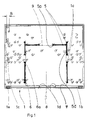
- the supply magazine made of plastic consists of a lower portion 1 with a bottom 1 a and with walls 1 arranged perpendicular thereto and extending around said bottom, as well as of a cover 2 covering the upper side of the lower portion 1.
- Cover 2 which is screwed to the lower portion 1 comprises a lid 3 which is pivotable about a pin 4 and associated with the unloading area of the supply magazine 1, 2.
- Lid 3 features a metal insert 7 which imparts to lid 3 the weight necessary for automatic closing.
- the free end of lid 3 is locked to the lower portion 1 by known means not illustrated.
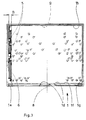
- Recesses 1 are arranged in the bottom 1 a of the lower portion 1, into which the plug-in bars 5 and 6 can be placed for defining the format, see Fig. 2.
- the plug-in bars 5, 6 feature projections 5a and 6a, respectively, which extend beyond the upper and the lower side of said bars, are arranged at their ends and are adapted for engagement with the recesses 1 c.
- the plug-in bars 5, 6 engage with their upper projections 5a , 6a recesses 2a in the cover 2.
- the lower recesses 1c and the upper recesses 2a are positioned opposite each other.
- one recess is circular and the other recess is designed as an oblong hole extending in the longitudinal direction of the plug-in bar.
- All of the recesses 2a in cover 2 are designed as oblong holes arranged in the longitudinal direction of the plug-in bars.
- the recesses 1 and 2a, respectively, in the bottom 1 a of the lower container portion 1 and in the cover 2 are associated with various sheet-film formats, the recesses 1 in the bottom 1 a being provided with numbers relating to the format so that when the plug-in bars 5, 6 are placed into the recesses 1 associated with a film format, the inner space is adapted to the desired film format.
- two long plug-in bars 6 and four short plug-in bars 5 are provided which serve for adapting the inner space to the film format desired. This adaptation takes place with respect to a center line 8 of the device so that a sheet film which is automatically removed can be transported by a sheet-film removal means in proper orientation to a sheet-film cassette positioned in the device.
- the front inner wall 1f of the lower portion 1 serves as a boundary for all sheet formats so that in connection with the alignment of the sheet film relative to the center line 8 of the device, constant access of a sheet-film removal means is possible, independently of the film format.
- the unloading area of the supply magazine 1, 2 is designed such that when cover 2 is screwed in position and lid 3 is open, a stack of film sheets can easily be loaded into the supply magazine 1, 2 in the direction of the arrow "A".
- the supply magazine 1, 2 is reloaded in a darkroom.
- plug-in bars 6 arranged therein are adequately long and thus bridge that area.
- Each of these longer plug-in bars 6 has only one projection 6a which extends beyond its upper side and engages a corresponding recess 2a in cover 2.
- the longer plug-in bars 6 always have to be inserted such that the individual projection 6a points upwardly and is adapted for engagement with recess 2a in the cover For this reason, and in order that the long plug-in bars 6 can be accommodated close to each other in a space-saving manner to be described, the bars have left/right marks related to the center line 8 of the device.
- the short plug-in bars 5 which are used in the area permanently covered by cover 2 do not require any left/right alignment as all of their projections 5a extend beyond the upper and lower side, respectively, and thus have a counter-support (recess 2a In cover 2) in any position.
- the plug-in bars 5 (and 6) are designed such that the sheet film 9 does not rest against the connecting bridge but always against projections 5a and 6a, respectively, which project upwardly and are continuously parallel with each other from the top to the bottom.
- the end-side projections 5a, 6a have a substantially oval cross-section extending transverse to the longitudinal extension of plug-in bars 5, 6, as can be seen from Fig. 4.
- the plug-in bars 5 In order to prevent the film sheets from striking against a projection 5a and 6a, respectively, when the supply magazine 1, 2 is loaded in the darkroom and the sheet film stack is not in a proper position, the plug-in bars 5 (and 6, respectively) have a ball-shaped elevation 5d arranged in the direction of insertion in front of the projection 5a and 6a, respectively. The stack of film sheets to be loaded is safely guided by these elevations 5d to the respective stack position without there being the danger of the stack getting jammed.
- the elevations 5d are arranged only on one side of the plug-in bars 5 (and 6, respectively) and do not extend beyond the size-defining plane formed by the projections 5a, 6a.
- the short plug-in bars 5 which can be selectively placed at the left or the right side are provided with two elevations 5d associated with the end-side projections 5a.
- the long plug-in bars 6 which have to be inserted in a predetermined left/right alignment are each provided with one elevation 5d only which is located in the direction of insertion in front of projection 6a.
- the plug-in bars 5 arranged parallel with the direction of insertion "A" have to be placed such that their ball-shaped elevations 5d face the center line 8 of the device.
- the plug-in bars 5 inserted parallel with the inner wall 1f need not be aligned in this way because they do not serve for guiding the sheet-film stack when the supply magazine is loaded.
- the plug-in bars 5 are provided with an eccentrically arranged connecting bridge so that these bars can be accommodated very close to each other in a staggered arrangement, as can also be seen from that Fig.
- the inner space of the lower portion 1 is designed such that when the largest possible sheet-film format (e.g. 35 x 43 cm) is used, three inner walls 1f, 1g, 1 serves as boundaries.
- the fourth side of the sheet-film format is defined by an inner row of one long and two short plug-in bars 5 and 6, respectively.
- the inner space of the lower portion 1 is enlarged by an amount "B" at the side defined by the plug-in bars 5, 6 so that there is enough space for the three size-defining plug-in bars 5, 6 and for the three plug-in bars 5 and 6, respectively, which are arranged parallel therewith and are not used.
- the enlarged area "B" required for that purpose is relatively small owing to the advantageous arrangement of plug-in bars 5 and 6 as described in Fig. 4.
- a rectangular film format e.g. 8" x 10
- the two long plug-in bars 6 and two short plug-in bars 5 arranged parallel with the inner wall 1f have to be inserted.
- the two short plug-in bars 5 not required remain in the lower portion 1 and are preferably placed in the enlarged area "B".
- the plug-in bars 5 not used can also be inserted into any suitable recesses 1 outside the desired film format.
- Fig. 8 shows an arrangement of the plug-in bars 5 and 6 for the same film format 8" x 10" that has been described above, however in a different orientation not in alignment with the center line 8 of the device.
- This embodiment is to show that the supply magazine 1, 2 can also be loaded with film sheets which are to be transported to sheet-film cassettes not in alignment with the center of the format, e.g. CRT cassettes.
- the displacement of the boundaries of the format (plug-in bars 5 and 6) relative to the center line 8 of the device exactly corresponds to the eccentric placement of the sheet film of a CRT cassette in the loading station of a loading device mentioned at the beginning. Even if the supply stack of film sheets is displaced like that, can the sheet film be unloaded and transferred by the same sheet-film removal means without any changes having to be made.
- plug positions can be used for various film formats such as 18 x 24 and 18 x 43.
- the plug-in bars 5 arranged parallel with the inner wall 1f are placed into the recesses 1 in the lower portion 1, which are marked "18".
- the long plug-in bars 6 are placed closer to the center line 8 of the device as can be seen from Fig. 7, while they are placed further apart in the case of the format 18 x 43 (not illustrated).
- This example of the handling of film formats having one identical side length is to show that when the recesses 1 c, 2a for the plug-in bars 5 and 6 are positioned cleverly, the inner space of the lower portion 1 can be easily adapted to the desired film format despite the great number of film formats.
- recesses 1d are provided into which nozzles of a sheet-film removal means (not illustrated) can enter, which are directed towards the front edge of the sheet film and serve for separating the individual film sheets.
- Each supply magazine 1 , 2 is provided at one outer end wall with printed data and a machine- readable code associated with the film format set.
- the projections of the plug-in bars 5 and 6 can also be circular 5b or rectangular 5c, as shown in Fig. 5 and 6.
- plug-in bars 5 and 6 with projections 5a and 5b and 5c, respectively, and 6a, and the ball-shaped elevations 5d is advantageous because they are injection-molded, the plug-in bars may also have different shapes.
- the plug-in bars facing the size-defining side can, for instance, have a surface (not illustrated) which connects the projections 5a and 5b, and 5c, respectively, and 6a, is substantially uninterrupted and straight or slightly concave, and also ensures easy loading of the supply magazine 1, 2.
- plugs can be used (not shown) which are placed into the recesses 1 and 2a, respectively, of the lower portion 1 and the cover 2, respectively.
- plugs may have a cross-section as shown, for instance, in Figs. 4 to 6.
Landscapes
- Physics & Mathematics (AREA)
- General Physics & Mathematics (AREA)
- Sheets, Magazines, And Separation Thereof (AREA)
- Stackable Containers (AREA)
- Apparatus For Radiation Diagnosis (AREA)
- Table Devices Or Equipment (AREA)
- Packages (AREA)
- Containers Having Bodies Formed In One Piece (AREA)
Claims (22)
Priority Applications (1)
| Application Number | Priority Date | Filing Date | Title |
|---|---|---|---|
| AT88904532T ATE82404T1 (de) | 1987-05-29 | 1988-05-24 | Behaelter fuer blattfilm. |
Applications Claiming Priority (3)
| Application Number | Priority Date | Filing Date | Title |
|---|---|---|---|
| DE3718130A DE3718130C2 (de) | 1987-05-29 | 1987-05-29 | Aufnahmebehälter für Blattfilm |
| DE3718130 | 1987-05-29 | ||
| PCT/EP1988/000463 WO1988009526A1 (en) | 1987-05-29 | 1988-05-24 | Container for receiving sheet film |
Publications (3)
| Publication Number | Publication Date |
|---|---|
| EP0359768A1 EP0359768A1 (de) | 1990-03-28 |
| EP0359768B1 true EP0359768B1 (de) | 1992-11-11 |
| EP0359768B2 EP0359768B2 (de) | 1996-03-06 |
Family
ID=6328697
Family Applications (1)
| Application Number | Title | Priority Date | Filing Date |
|---|---|---|---|
| EP88904532A Expired - Lifetime EP0359768B2 (de) | 1987-05-29 | 1988-05-24 | Behälter für blattfilm |
Country Status (5)
| Country | Link |
|---|---|
| US (1) | US5042662A (de) |
| EP (1) | EP0359768B2 (de) |
| AT (1) | ATE82404T1 (de) |
| DE (2) | DE3718130C2 (de) |
| WO (1) | WO1988009526A1 (de) |
Families Citing this family (6)
| Publication number | Priority date | Publication date | Assignee | Title |
|---|---|---|---|---|
| DE4130562A1 (de) * | 1991-09-13 | 1993-04-01 | Agfa Gevaert Ag | Magazin fuer blattfilme und entnahme von filmen |
| US5447234A (en) * | 1992-11-13 | 1995-09-05 | Eastman Kodak Company | Recyclable/reusable containers for packaging graphical sheet materials |
| US5685429A (en) * | 1992-11-13 | 1997-11-11 | Eastman Kodak Company | Adjustable chocking element |
| DE4427783C1 (de) * | 1994-08-05 | 1996-02-01 | Agfa Gevaert Ag | Behälter zur Aufnahme eines blattförmigen Mediums für Röntgenbilder |
| FR2744097B1 (fr) * | 1996-01-30 | 1998-03-27 | Kodak Pathe | Emballage pour produits plats de divers formats |
| GB2418663B (en) * | 2004-09-22 | 2006-11-01 | Loadhog Ltd | Palletised loads of containers |
Family Cites Families (22)
| Publication number | Priority date | Publication date | Assignee | Title |
|---|---|---|---|---|
| DE7205852U (de) * | 1972-05-18 | Kleiber G | Versand- oder Aufbewahrungstasche für Fotografien od. dgl | |
| DE632464C (de) * | 1935-03-21 | 1936-07-08 | Kodak Akt Ges | Papierhalter an photographischen Vergroesserungsgeraeten |
| US2320835A (en) * | 1941-05-19 | 1943-06-01 | Ditto Inc | Hectograph blanket conditioning container |
| US3155264A (en) * | 1962-02-15 | 1964-11-03 | Shook Alvin Lee | Cases for photographic film |
| US3384228A (en) * | 1966-10-10 | 1968-05-21 | Union Camp Corp | Bobbin package |
| US3521748A (en) * | 1968-06-27 | 1970-07-28 | Inland Container Corp | Adjustable depth carton |
| UST875025I4 (en) * | 1969-10-13 | 1970-06-30 | Heinz c | |
| DE1963926B1 (de) * | 1969-12-20 | 1971-08-26 | Bernhard Markwitz | Versandbehaelter fuer Mikroskop-Objekttraeger |
| GB1298412A (en) * | 1970-06-29 | 1972-12-06 | Gas Council | Protectives for photographic materials |
| US3710975A (en) * | 1971-09-20 | 1973-01-16 | Pantasote Co Of New York Inc | Trays for photographic slides |
| US3858720A (en) * | 1973-02-23 | 1975-01-07 | Media Systems Corp | Curriculum container assembly |
| US4060929A (en) * | 1976-02-13 | 1977-12-06 | Marvin Glass & Associates | Toy detective set |
| DE2917547C2 (de) * | 1979-04-30 | 1981-11-19 | Agfa-Gevaert Ag, 5090 Leverkusen | Röntgen-Filmkassette |
| DE3122583C2 (de) * | 1981-06-06 | 1985-05-15 | Agfa-Gevaert Ag, 5090 Leverkusen | Vorrichtung zum Be- und Entladen von Röntgenfilmkassetten |
| IT8234009V0 (it) * | 1982-03-26 | 1982-03-26 | Zanussi Componenti Plastica | Cassetta per formaggi. |
| US4407411A (en) * | 1982-06-24 | 1983-10-04 | Hartzell Manufacturing, Inc. | Storage box |
| DE3565012D1 (en) * | 1984-04-04 | 1988-10-20 | Fuji Photo Film Co Ltd | Cassette for stimulable phosphor sheet |
| DE3533954A1 (de) * | 1985-09-24 | 1987-03-26 | Agfa Gevaert Ag | Automatisch be- und entladbare roentgenfilmkassette und hierfuer geeignetes roentgenfilmkassettenbe- und -entladegeraet |
| US4783019A (en) * | 1986-02-14 | 1988-11-08 | Agfa-Gevaert Ag | Film supply magazine for film sheet packs provided with light-sealing sheathings |
| JPH0629952B2 (ja) * | 1986-06-27 | 1994-04-20 | 富士写真フイルム株式会社 | 感光性シ−トフイルム用包装体 |
| US4778056A (en) * | 1987-08-14 | 1988-10-18 | Eastman Kodak Company | Container adapter |
| GB8803587D0 (en) * | 1988-02-17 | 1988-03-16 | Visual Inspection Automation L | Storage receptacles for drill bits |
-
1987
- 1987-05-29 DE DE3718130A patent/DE3718130C2/de not_active Expired - Fee Related
-
1988
- 1988-05-24 AT AT88904532T patent/ATE82404T1/de not_active IP Right Cessation
- 1988-05-24 WO PCT/EP1988/000463 patent/WO1988009526A1/en not_active Ceased
- 1988-05-24 EP EP88904532A patent/EP0359768B2/de not_active Expired - Lifetime
- 1988-05-24 DE DE3875968T patent/DE3875968T2/de not_active Expired - Fee Related
-
1990
- 1990-11-27 US US07/617,940 patent/US5042662A/en not_active Expired - Lifetime
Also Published As
| Publication number | Publication date |
|---|---|
| US5042662A (en) | 1991-08-27 |
| DE3718130C2 (de) | 1995-01-19 |
| DE3875968D1 (de) | 1992-12-17 |
| ATE82404T1 (de) | 1992-11-15 |
| EP0359768B2 (de) | 1996-03-06 |
| EP0359768A1 (de) | 1990-03-28 |
| DE3875968T2 (de) | 1996-10-24 |
| WO1988009526A1 (en) | 1988-12-01 |
| DE3718130A1 (de) | 1988-12-15 |
Similar Documents
| Publication | Publication Date | Title |
|---|---|---|
| EP0526716B1 (de) | Palette zum Halten einer Kassette | |
| ES2216241T3 (es) | Precinto. | |
| EP0359768B1 (de) | Behälter für blattfilm | |
| KR100427468B1 (ko) | 카세트 수납 케이스 | |
| CA1132504A (en) | Magazine for magnetic tape cassettes | |
| JPS5817942B2 (ja) | X線フイルムの装填排出装置 | |
| EP1564013A3 (de) | Aufzeichnungsblattpaket und Blattzuführungskassette für einen Drucker | |
| EP0535978A2 (de) | Magnetbandkassettenbehälter | |
| US5143252A (en) | Portable package and system for storing and dispensing photographic film cartridges | |
| US5871696A (en) | Cassette for blood smear slides and cooperative slide ejection assembly | |
| US4009781A (en) | Slide tray and tape cassette container | |
| US5297787A (en) | Sheet cassette | |
| ATE216338T1 (de) | Stapelbarer transportbehälter | |
| US5338021A (en) | Paper feeding mechanism | |
| EP0864435B1 (de) | Überfüllschutzvorrichtung für ein Aufzeichnungsträgereingabefach | |
| EP0231008A3 (en) | Stackable plastic crate | |
| JPH02231332A (ja) | 像記録シートの供給 | |
| US5058878A (en) | Cassette structure | |
| US7165685B2 (en) | System, method, and apparatus for improved packaging of data tape cartridges | |
| EP0607519A1 (de) | Palette zum halten einer kassette | |
| WO1988006750A2 (en) | Automatic film-loading device for sheet film cassettes | |
| JPS628040Y2 (de) | ||
| JP3016893U (ja) | デイスケツトカセツト | |
| SU1295544A1 (ru) | Устройство дл поштучной подачи изделий,преимущественно кассет дл радиодеталей | |
| JP4364500B2 (ja) | カード収容カートリッジ |
Legal Events
| Date | Code | Title | Description |
|---|---|---|---|
| PUAI | Public reference made under article 153(3) epc to a published international application that has entered the european phase |
Free format text: ORIGINAL CODE: 0009012 |
|
| 17P | Request for examination filed |
Effective date: 19891121 |
|
| AK | Designated contracting states |
Kind code of ref document: A1 Designated state(s): AT CH DE FR GB IT LI NL SE |
|
| 17Q | First examination report despatched |
Effective date: 19920415 |
|
| GRAA | (expected) grant |
Free format text: ORIGINAL CODE: 0009210 |
|
| ITF | It: translation for a ep patent filed | ||
| AK | Designated contracting states |
Kind code of ref document: B1 Designated state(s): AT CH DE FR GB IT LI NL SE |
|
| REF | Corresponds to: |
Ref document number: 82404 Country of ref document: AT Date of ref document: 19921115 Kind code of ref document: T |
|
| REF | Corresponds to: |
Ref document number: 3875968 Country of ref document: DE Date of ref document: 19921217 |
|
| ET | Fr: translation filed | ||
| PLBI | Opposition filed |
Free format text: ORIGINAL CODE: 0009260 |
|
| 26 | Opposition filed |
Opponent name: AGFA-GEVAERT AG PATENTABTEILUNG LG Effective date: 19930809 |
|
| NLR1 | Nl: opposition has been filed with the epo |
Opponent name: AGFA-GEVAERT AG |
|
| EAL | Se: european patent in force in sweden |
Ref document number: 88904532.4 |
|
| PUAH | Patent maintained in amended form |
Free format text: ORIGINAL CODE: 0009272 |
|
| STAA | Information on the status of an ep patent application or granted ep patent |
Free format text: STATUS: PATENT MAINTAINED AS AMENDED |
|
| ITF | It: translation for a ep patent filed | ||
| 27A | Patent maintained in amended form |
Effective date: 19960306 |
|
| AK | Designated contracting states |
Kind code of ref document: B2 Designated state(s): AT CH DE FR GB IT LI NL SE |
|
| REG | Reference to a national code |
Ref country code: CH Ref legal event code: AEN Free format text: MAINTIEN DU BREVET DONT L'ETENDUE A ETE MODIFIEE |
|
| NLR2 | Nl: decision of opposition | ||
| NLR3 | Nl: receipt of modified translations in the netherlands language after an opposition procedure | ||
| ET3 | Fr: translation filed ** decision concerning opposition | ||
| PLAW | Interlocutory decision in opposition |
Free format text: ORIGINAL CODE: EPIDOS IDOP |
|
| PGFP | Annual fee paid to national office [announced via postgrant information from national office to epo] |
Ref country code: NL Payment date: 20000320 Year of fee payment: 13 |
|
| PGFP | Annual fee paid to national office [announced via postgrant information from national office to epo] |
Ref country code: AT Payment date: 20000404 Year of fee payment: 13 |
|
| PGFP | Annual fee paid to national office [announced via postgrant information from national office to epo] |
Ref country code: SE Payment date: 20000504 Year of fee payment: 13 |
|
| PGFP | Annual fee paid to national office [announced via postgrant information from national office to epo] |
Ref country code: CH Payment date: 20000621 Year of fee payment: 13 |
|
| PG25 | Lapsed in a contracting state [announced via postgrant information from national office to epo] |
Ref country code: AT Free format text: LAPSE BECAUSE OF NON-PAYMENT OF DUE FEES Effective date: 20010524 |
|
| PG25 | Lapsed in a contracting state [announced via postgrant information from national office to epo] |
Ref country code: SE Free format text: LAPSE BECAUSE OF NON-PAYMENT OF DUE FEES Effective date: 20010525 |
|
| PG25 | Lapsed in a contracting state [announced via postgrant information from national office to epo] |
Ref country code: LI Free format text: LAPSE BECAUSE OF NON-PAYMENT OF DUE FEES Effective date: 20010623 Ref country code: CH Free format text: LAPSE BECAUSE OF NON-PAYMENT OF DUE FEES Effective date: 20010623 |
|
| PG25 | Lapsed in a contracting state [announced via postgrant information from national office to epo] |
Ref country code: NL Free format text: LAPSE BECAUSE OF NON-PAYMENT OF DUE FEES Effective date: 20011201 |
|
| REG | Reference to a national code |
Ref country code: GB Ref legal event code: IF02 |
|
| REG | Reference to a national code |
Ref country code: CH Ref legal event code: PL |
|
| NLV4 | Nl: lapsed or anulled due to non-payment of the annual fee |
Effective date: 20011201 |
|
| PGFP | Annual fee paid to national office [announced via postgrant information from national office to epo] |
Ref country code: GB Payment date: 20020404 Year of fee payment: 15 |
|
| PGFP | Annual fee paid to national office [announced via postgrant information from national office to epo] |
Ref country code: FR Payment date: 20020503 Year of fee payment: 15 |
|
| PG25 | Lapsed in a contracting state [announced via postgrant information from national office to epo] |
Ref country code: GB Free format text: LAPSE BECAUSE OF NON-PAYMENT OF DUE FEES Effective date: 20030524 |
|
| PGFP | Annual fee paid to national office [announced via postgrant information from national office to epo] |
Ref country code: DE Payment date: 20030530 Year of fee payment: 16 |
|
| GBPC | Gb: european patent ceased through non-payment of renewal fee |
Effective date: 20030524 |
|
| PG25 | Lapsed in a contracting state [announced via postgrant information from national office to epo] |
Ref country code: FR Free format text: LAPSE BECAUSE OF NON-PAYMENT OF DUE FEES Effective date: 20040130 |
|
| REG | Reference to a national code |
Ref country code: FR Ref legal event code: ST |
|
| PG25 | Lapsed in a contracting state [announced via postgrant information from national office to epo] |
Ref country code: DE Free format text: LAPSE BECAUSE OF NON-PAYMENT OF DUE FEES Effective date: 20041201 |
|
| PG25 | Lapsed in a contracting state [announced via postgrant information from national office to epo] |
Ref country code: IT Free format text: LAPSE BECAUSE OF NON-PAYMENT OF DUE FEES;WARNING: LAPSES OF ITALIAN PATENTS WITH EFFECTIVE DATE BEFORE 2007 MAY HAVE OCCURRED AT ANY TIME BEFORE 2007. THE CORRECT EFFECTIVE DATE MAY BE DIFFERENT FROM THE ONE RECORDED. Effective date: 20050524 |