EP0359860A1 - Dispositif et procédé de mise en oeuvre d'au moins une lampe à décharge - Google Patents
Dispositif et procédé de mise en oeuvre d'au moins une lampe à décharge Download PDFInfo
- Publication number
- EP0359860A1 EP0359860A1 EP88115709A EP88115709A EP0359860A1 EP 0359860 A1 EP0359860 A1 EP 0359860A1 EP 88115709 A EP88115709 A EP 88115709A EP 88115709 A EP88115709 A EP 88115709A EP 0359860 A1 EP0359860 A1 EP 0359860A1
- Authority
- EP
- European Patent Office
- Prior art keywords
- frequency
- lamp
- gas discharge
- discharge lamp
- generator
- Prior art date
- Legal status (The legal status is an assumption and is not a legal conclusion. Google has not performed a legal analysis and makes no representation as to the accuracy of the status listed.)
- Withdrawn
Links
- 238000000034 method Methods 0.000 title claims abstract description 20
- 238000012806 monitoring device Methods 0.000 claims description 13
- 238000012544 monitoring process Methods 0.000 claims description 3
- 239000003990 capacitor Substances 0.000 description 35
- 238000004804 winding Methods 0.000 description 11
- 230000000295 complement effect Effects 0.000 description 6
- 229910052736 halogen Inorganic materials 0.000 description 3
- 150000002367 halogens Chemical class 0.000 description 3
- 206010000210 abortion Diseases 0.000 description 2
- 230000006978 adaptation Effects 0.000 description 2
- 230000007547 defect Effects 0.000 description 2
- 230000001419 dependent effect Effects 0.000 description 2
- 238000011161 development Methods 0.000 description 2
- 230000018109 developmental process Effects 0.000 description 2
- 238000010586 diagram Methods 0.000 description 2
- 230000000694 effects Effects 0.000 description 2
- 230000004913 activation Effects 0.000 description 1
- 230000000903 blocking effect Effects 0.000 description 1
- 238000007599 discharging Methods 0.000 description 1
- 230000002349 favourable effect Effects 0.000 description 1
- 238000010438 heat treatment Methods 0.000 description 1
- 230000007257 malfunction Effects 0.000 description 1
- 238000004519 manufacturing process Methods 0.000 description 1
- 230000001105 regulatory effect Effects 0.000 description 1
- 238000010079 rubber tapping Methods 0.000 description 1
- 238000004904 shortening Methods 0.000 description 1
- 238000003860 storage Methods 0.000 description 1
Images


Classifications
-
- H—ELECTRICITY
- H05—ELECTRIC TECHNIQUES NOT OTHERWISE PROVIDED FOR
- H05B—ELECTRIC HEATING; ELECTRIC LIGHT SOURCES NOT OTHERWISE PROVIDED FOR; CIRCUIT ARRANGEMENTS FOR ELECTRIC LIGHT SOURCES, IN GENERAL
- H05B41/00—Circuit arrangements or apparatus for igniting or operating discharge lamps
- H05B41/14—Circuit arrangements
- H05B41/36—Controlling
- H05B41/38—Controlling the intensity of light
- H05B41/382—Controlling the intensity of light during the transitional start-up phase
-
- H—ELECTRICITY
- H05—ELECTRIC TECHNIQUES NOT OTHERWISE PROVIDED FOR
- H05B—ELECTRIC HEATING; ELECTRIC LIGHT SOURCES NOT OTHERWISE PROVIDED FOR; CIRCUIT ARRANGEMENTS FOR ELECTRIC LIGHT SOURCES, IN GENERAL
- H05B41/00—Circuit arrangements or apparatus for igniting or operating discharge lamps
- H05B41/14—Circuit arrangements
- H05B41/26—Circuit arrangements in which the lamp is fed by power derived from DC by means of a converter, e.g. by high-voltage DC
- H05B41/28—Circuit arrangements in which the lamp is fed by power derived from DC by means of a converter, e.g. by high-voltage DC using static converters
- H05B41/295—Circuit arrangements in which the lamp is fed by power derived from DC by means of a converter, e.g. by high-voltage DC using static converters with semiconductor devices and specially adapted for lamps with preheating electrodes, e.g. for fluorescent lamps
- H05B41/298—Arrangements for protecting lamps or circuits against abnormal operating conditions
- H05B41/2981—Arrangements for protecting lamps or circuits against abnormal operating conditions for protecting the circuit against abnormal operating conditions
-
- Y—GENERAL TAGGING OF NEW TECHNOLOGICAL DEVELOPMENTS; GENERAL TAGGING OF CROSS-SECTIONAL TECHNOLOGIES SPANNING OVER SEVERAL SECTIONS OF THE IPC; TECHNICAL SUBJECTS COVERED BY FORMER USPC CROSS-REFERENCE ART COLLECTIONS [XRACs] AND DIGESTS
- Y02—TECHNOLOGIES OR APPLICATIONS FOR MITIGATION OR ADAPTATION AGAINST CLIMATE CHANGE
- Y02B—CLIMATE CHANGE MITIGATION TECHNOLOGIES RELATED TO BUILDINGS, e.g. HOUSING, HOUSE APPLIANCES OR RELATED END-USER APPLICATIONS
- Y02B20/00—Energy efficient lighting technologies, e.g. halogen lamps or gas discharge lamps
-
- Y—GENERAL TAGGING OF NEW TECHNOLOGICAL DEVELOPMENTS; GENERAL TAGGING OF CROSS-SECTIONAL TECHNOLOGIES SPANNING OVER SEVERAL SECTIONS OF THE IPC; TECHNICAL SUBJECTS COVERED BY FORMER USPC CROSS-REFERENCE ART COLLECTIONS [XRACs] AND DIGESTS
- Y10—TECHNICAL SUBJECTS COVERED BY FORMER USPC
- Y10S—TECHNICAL SUBJECTS COVERED BY FORMER USPC CROSS-REFERENCE ART COLLECTIONS [XRACs] AND DIGESTS
- Y10S315/00—Electric lamp and discharge devices: systems
- Y10S315/04—Dimming circuit for fluorescent lamps
Definitions
- the invention relates to a method for operating at least one gas discharge lamp according to the preamble of claim 1 and an apparatus for performing the method.
- a method for operating a low-voltage halogen lamp is described, for example, in Siemens Components 22, 1984, number 6 on pages 249 to 254. From this publication, a 100 kHz switching power supply is known as an externally controlled lamp generator for feeding the low-voltage halogen lamp. The brightness of the halogen lamp can be changed by changing the operating frequency of the switching power supply. With this known circuit arrangement, however, it is not possible to operate gas discharge lamps, in particular fluorescent lamps. Such gas discharge lamps have to be preheated for reliable ignition and then ignited with a briefly high voltage. Such a control is not possible with the known circuit arrangement.
- lamp generators which provide self-oscillating half-bridge circuits with bipolar transistors through feedback.
- Such self-oscillating lamp generators are described, for example, in DE-OS 33 01 108 or DE-OS 35 11 661.
- fluorescent lamps cannot be preheated precisely and glow discharges occur.
- a free-swinging lamp generator is inexpensive, but the spread of the electrical properties of the bipolar transistors (e.g. gain factor, storage time) is particularly problematic in mass production.
- the temperature-dependent saturation behavior of the current transformer used in free-swinging lamp generators creates a temperature drift that must be compensated with additional effort.
- dimming the fluorescent lamp is also only possible by changing the input voltage. This variation of the input voltage is difficult to implement due to the rectification of the mains and the required sine current consumption from the mains.
- the invention is based on the object of specifying a method for operating gas discharge lamps, in particular fluorescent lamps, which enables preheating which is gentle on the lamp, reliable ignition, high efficiency in regulated nominal operation and power control of the gas discharge lamp.
- the harmonic filter II consists of a generally known step-up converter, which has a charging choke 1, a free-wheeling diode 2, a switching transistor 3 which can be controlled by a control unit 4, and a charging capacitor 5.
- a control unit 4 z.
- the integrated circuit TDA 4814 from Siemens can be used.
- the harmonic filter II has two output terminals 6, 7, between which a rectified voltage is applied.
- the second output terminal 7 is at ground potential.
- the externally controlled lamp generator III is connected to these output terminals 6 and 7.
- the externally controlled lamp generator III has a control device 8, at the output terminals 11, 12 z. B.
- this transformer 17 has two secondary windings, to each of which an electrical switching element 18, 19 with its control path is connected.
- the gate connections G and source connections S of these transistors are connected to the secondary windings of the transformer 17 in the manner described above.
- the output terminal 6 of the harmonic filter II is also connected via a first capacitor 21 to a first terminal 60 of a gas discharge lamp 22, preferably a fluorescent lamp.
- An oscillating circuit choke 23 is connected between a second connection terminal 61 of the gas discharge lamp 22 and the connection point 20 of the half bridge. Parallel to the gas discharge lamp 22, a second capacitor 24 is arranged.
- the first connection terminal 60 of the gas discharge lamp 22 is also connected via a third capacitor 25 to the source terminal S of the SIPMOS® transistor forming the second electrical switching element 19.
- the externally controlled lamp generator III additionally has means for detecting at least the current through the gas discharge lamp 22.
- a quantity for the lamp current, the lamp voltage and the resonant circuit current is fed in via connecting lines 40, 41, 42, 43.
- the lamp current is measured with a residual current transformer.
- the power supply to the control device 8 is advantageously carried out for self-starting via a high-resistance resistor 26 which is connected between the connecting terminal 6 and the input terminal 9 of the control device 8.
- the constant power supply to the control device 8 after the self-start can take place in a known manner, not shown here for reasons of better clarity, by the power section of the externally controlled lamp generator III from an auxiliary winding on the resonant circuit reactor 23 or from a charge pump tapping at the connection point 20 of the half bridge by means of a capacitor.
- An input terminal 10 of the control device 8 is connected to the reference potential.
- a fourth capacitor 27 is connected between the input terminals 8 and 10 of the control device 8.
- the circuit arrangement shown in FIG. 2 differs from that shown in FIG. 1 only in that the externally controlled lamp generator III has a single-ended converter with a transformer 30 and a single electrical switching element 31.
- the reference symbols already known from FIG. 1 are used further in the circuit arrangement according to FIG. 2 for parts having the same effect.
- the control path of the electrical switching element 31 is now connected to the output terminals 11 and 12 of the control device 8.
- a primary winding 30a of the transformer 30 is connected to the output of the electrical switching element 31.
- a first secondary winding 30b of the transformer 30 is connected between the connection terminal 6 and a diode 32 connected with its anode to reference potential.
- a series resonant circuit consisting of an oscillating circuit choke 33 and a capacitor 34 is connected in parallel with a second secondary winding 30c of this transformer 30.
- the gas discharge lamp preferably a fluorescent lamp, 22 with its connecting terminals 60 and 61 is arranged parallel to this capacitor 34.
- the circuit arrangement according to FIG. 2 also has means for detecting at least the resonant circuit current, preferably also the lamp current and the lamp voltage. The measured values are passed to the input terminals 13, 14, 15 and 16 of the control device 8 via connecting lines 40, 41, 42 and 43.
- the lamp current is measured with a residual current transformer.
- the lamp generator is supplied with current as described in connection with FIG. 1.
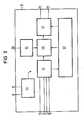
- This control device 8 has a frequency generator 50 which can be varied in frequency with a downstream driver stage 51 and a condition monitoring device 52 for monitoring at least the current of the gas discharge lamp 22.
- the status monitoring device 52 is connected to the already known connection terminals 13, 14, 15 and 16.
- the control unit 8 also contains a sequence control device 53 which is connected to the status monitoring device 52, the frequency generator 50 and the driver stage 51. It is also provided that a predetermined signal is fed to a setpoint input device 55 via a connection terminal 28.
- the setpoint specification device 55 uses this signal to generate a setpoint for the output frequency of the frequency generator 50, which can be set as a function of this setpoint.
- the control device 8 also has a power supply device 54 which is connected to the already known input terminals 9 and 10.
- This power supply device 54 includes a start-up circuit for starting the externally controlled lamp generator III already known in connection with FIGS. 1 and 2 and for the internal power supply of the control device 8.
- the connecting lines of the power supply devices 54 to the individual components of the control unit 8 are not shown in FIG. 3 for the sake of clarity.
- the start-up circuit included in the power supply device 54 has the effect that a capacitor connected externally to the control unit 8 is charged and, after an upper threshold voltage has been reached, a self-start with subsequent self-supply by the power section of the externally controlled lamp generator III can take place before a lower threshold voltage with a new self-start state is reached .
- a bipolar transistor or MOS transistor directly or one or more switching transistors can be controlled potential-free via a transformer.
- the status monitoring device 52 in cooperation with the sequence control device 53, can block the output of the driver stage 51 and / or change the frequency of the frequency generator 50 upwards in the event of a fault. If the fault persists, this state is maintained until a suitable reset signal cancels the said block or the operating frequency f B of the frequency generator 50 is reduced.
- the method according to the invention for operating a gas discharge lamp 22, in particular a fluorescent lamp is shown as follows on the basis of the course of the operating frequency f B shown in FIG. 4a for an ignitable gas discharge lamp 22:
- the operating frequency f B of the lamp generator becomes larger, preferably at least by the factor 1.5, chosen as the nominal frequency f N in nominal operation, ie at 100% load.
- the operating frequency f B is reduced until the gas discharge lamp 22 has a predetermined zu has reached. This predefined state is monitored and the lamp state, which z. B. results from the lamp current and / or the lamp voltage.
- the operating frequency f B is kept at least at its current value, namely until the gas discharge lamp 22 ignites.
- the operating frequency f B is reduced to the nominal frequency f N and the nominal operation c of the gas discharge lamp is initiated.
- the operating frequency f B for dimming and thus for adjusting the brightness of the gas discharge lamp can be varied.
- a safety operation of the externally controlled lamp generator is initiated in the event of a malfunction, e.g. a defect in the discharge path of the gas discharge lamp 22, a deviation from normal operation, etc..
- This safety operation can consist in increasing the operating frequency f B and / or the externally controlled lamp generator being blocked.
- the high-frequency AC voltage of the externally controlled lamp generator is fed into a resonance circuit connected to the gas discharge lamp 22, the resonance frequency f U of the resonance circuit when the gas discharge lamp is not ignited being greater than the nominal frequency f N , but the resonance frequency f Z when the gas discharge lamp is ignited is chosen to be smaller than the nominal frequency f N , and that the operating frequency f B in the preheating phase a is set to be greater than the resonance frequency f U when the gas discharge lamp is not ignited.
- FIG. 4b shows the voltage curve u L on the gas discharge lamp, as it results when the operating frequency f B is set using the method according to the invention.
- u LNen denotes the voltage applied to the gas discharge lamp 22 during nominal operation, that is to say at full load. It can be clearly seen in FIG. 4b that with the lowering of the operating frequency f B to Be at the beginning of the starting phase b, the lamp voltage u L rises and the ignition of the gas discharge lamp 22 starts.
- 4c shows the current profile i L of the gas discharge lamp belonging to FIGS. 4a and 4b and the current profile of the resonance circuit i Schu .
- FIG. 5 shows in detail an exemplary embodiment of a circuit arrangement for the control device 8 mentioned.
- the same reference numerals are used in this FIG 5 for the already known switching elements.
- the frequency generator 50 has a first voltage-controlled oscillator 100, the first input terminal 101 of which is connected to ground potential via a capacitor 103.
- a second input terminal 102 of this first voltage-controlled oscillator 100 is also connected to ground potential via a resistor 104.
- the input terminal 102 is also connected to a resistor 105, which in turn is connected to ground via a further capacitor 106.
- the connection point between resistor 105 and capacitor 106 is connected to an input terminal 107 of control device 8. This input terminal 107 is connected to a current sink 112.
- the output terminal 108 of the voltage-controlled oscillator 100 is connected to the clock input of a flip-flop 109.
- the inverting output Q this flip-flop 109 is connected to an input terminal 115 of an AND gate 110 of the driver stage 51.
- the non-inverting output Q of the flip-flop 109 is connected to an input terminal 118 of a further AND gate 111 of the driver stage 51.
- the input terminal 10 of the control device 8 is connected to further input terminals 116 and 119 of the AND gates 110 and 111 via a resistor 125.
- these input terminals 116 and 119 are connected to the anode of a thyristor 126.
- the cathode connection of this thyristor 126 is at ground potential.
- the AND gates 110 and 111 each have a further input 117 and 120, which are connected to the non-inverting output Q of an RS flip-flop 114.
- the S Input of this RS flip-flop 114 is connected to the output terminal 108 of the voltage-controlled oscillator 100.
- the R -Input of the RS flip-flop 114 is via an inverter 113 with the current sink 112 in connection.
- the control terminals of complementary emitter followers, consisting of the transistors 121 and 122 or 123 and 124 provided with free-wheeling diodes, are connected to the output terminals of the AND gates 110 and 111, respectively.
- the complementary emitter follower formed from the transistors 121 and 122 consists of an npn transistor 121 and a pnp transistor 122, the base connections of which are connected to the output terminal of the AND gate 110.
- the emitter connections of the transistors 121 and 122 are connected together to the output terminal 11, while the collector connection of the NPN transistor 121 is connected to the input terminal 10 and the collector connection of the PNP transistor 122 is connected to the input terminal 9, that is to say to ground.
- the second complementary emitter follower, consisting of transistors 123 and 124, is connected to AND gate 111 in a corresponding manner.
- the control device 8 also has a first comparator 127 and a second comparator 128.
- the inverting input of the comparator 127 is connected to the input terminal 13 and the non-inverting input of the comparator 128 to the input terminal 14.
- the non-inverting input of the comparator 127 and the inverting input of the comparator 128 are connected to an output terminal of the power supply 54, which provides the reference voltage U ref for the control device 8.
- the power supply device 54 has it Furthermore, another output, at which the voltage U V required to supply the control device 8 is present.
- the power supply device 54 is connected to the already known terminals 9 and 10 of the control device 8. Terminal 9 is grounded.
- the output terminal of the comparator 127 already described is connected to the R -Input of the RS flip-flop 114 connected.
- the second comparator 128 of the sequence control device 53 with the status monitoring device 52 is connected at its output via an inverter 129 to an input terminal 131 of a second voltage-controlled oscillator 130.
- the output frequency of this second voltage-controlled oscillator 130 can be determined via a capacitor 135 that can be connected to an input terminal 134.
- the output of this second voltage-controlled oscillator 130 is connected to a first delay stage 136, which in turn is in contact with a second delay stage 137.
- the second voltage-controlled oscillator 130 is also connected to the power supply device 54.
- Another output of the first delay stage 136 is connected to an input of an OR gate 140 and an input of a further AND gate 138.
- the output of the second delay stage 137 is connected to a further input of the AND gate 138.
- the signal present at the output of the second comparator 128 reaches an additional input of the AND gate 138 via an inverting element 139.
- the output of this AND gate 138 is in contact with the gate electrode of the thyristor 126.
- the signal present at the second differential amplifier 128 also reaches a further input of the OR gate 140 via a further connecting line, the inverting output of which is connected to the base connection of an npn transistor 141.
- the emitter connection of this NPN transistor 141 is at ground potential, while the collector connection is connected to the already known connection terminal 107.
- the anode of a diode 154 whose cathode connection is connected to the output of a differential amplifier 153, is also connected to the collector terminal of this transistor 141.
- the inverting input of this third differential amplifier 153 is connected to a connection terminal 159 of the control device 8, to which the current measured at the gas discharge lamp is fed via a resistor 157.
- Both a capacitor 156 and a resistor 155 are connected in parallel between the cathode connection of the diode 154 and the terminal 159.
- a resistor 151 is connected between a further terminal 158 and the non-inverting input of the differential amplifier 153.
- the non-inverting input of the differential amplifier 153 is in contact with the cathode connection of a further diode 150, the anode connection of which is connected to the output of the inverter 129.
- a setpoint can optionally be specified via a switching device 152, which is obtained from a reference voltage source with constant lamp power or with adjustable lamp power from a setpoint processing.
- This setpoint processing can, for. B. consist of an adaptation amplifier 169 with low-pass behavior, with which, for example, an analog control signal from a brightness sensor or a signal encoded by pulse width modulation can be adapted to the lamp current control via an optocoupler.
- the adaptation amplifier with low-pass behavior can, for. B. consist - as shown in FIG 5 - that the inverting input of a differential amplifier 169 is connected to a connection terminal 162 which is connected to ground potential via a resistor 166.
- the non-inverting input of this differential amplifier 169 is connected to an input terminal 163, which is also connected to ground via a resistor 167.
- the output of differential amplifier 169 is connected to the anode of a diode 170 and to a connection terminal 161.
- the cathode connection of the diode 170 is connected to the voltage U ref of the power supply device 54.
- the parallel connection of a capacitor 164 and a resistor 165 is arranged between the connecting terminal 161 and the connecting terminal 162.
- the input terminal 158 can optionally be connected to the terminal 160 at which the reference voltage U ref is present, or can be switched to input terminal 161.
- a photo element e.g. B. a photo transistor 168 connected with its load path.
- the circuit arrangement presented here can also be implemented in an integrated form.
- the mode of operation of this circuit arrangement is as follows:
- the resistor 27 is used to charge the capacitor 27 connected between the input terminals 9 and 10 of the control device 8 from the rectified mains voltage.
- a standby function of the power supply 54 prevents current consumption by the control device 8 and monitors the charging process with low self-consumption. As soon as an upper threshold voltage is reached, the power supply device 54 releases the current for the control device 8. The necessary energy is drawn from the capacitor 27 until either self-supply via the power section of the externally controlled lamp generator III is possible or until the capacitor voltage reaches a lower threshold voltage and the standby mode starts again.
- the frequency generator 59 begins with the operating frequency f B which is provided for the preheating phase of the fluorescent lamp and is determined by the capacitor 103 and the resistors 104 and 105.
- the resistors 104 and 105 act on the current mirror 112 for charging the capacitor 103.
- the capacitor 106 is discharged or short-circuited, the parallel connection of the resistors 105 and 104 acts.
- the condition monitoring device 52 recognizes in this operating phase that the lamp current fed in at the input terminal 14 is the same or almost the same Zero is and initiates the accident activation.
- the capacitor 106 is short-circuited, whereby the operating frequency f B is set according to the invention.
- the lamp current control is blocked and a first delay stage is activated activated. During this first delay period of e.g. B. 0.3 to 0.5 sec., The gas discharge lamp is preheated.
- condition monitoring device 52 recognizes normal operation by the now flowing lamp current, aborts the sequence control and releases the lamp current control.
- the ignition process is initiated after the end of the first delay stage 136 and the second delay stage 137 is activated.
- the short circuit of the capacitor 106 is released, whereby the capacitor 103 is slowly charged via the resistor 105 and the operating frequency f B drops.
- the lowest operating frequency is determined by the resistor 104, which is preferably lower than the resonance frequency f U of the unloaded lamp resonant circuit.
- the lowest operating frequency f B is not reached during the ignition phase, because the current limitation intervenes to protect the transistors in the vicinity of the resonance frequency.
- the current limitation acts when a predetermined threshold value is exceeded by immediately blocking the transistors (shortening the switch-on time) and also by gradually increasing the operating frequency f B by discharging the capacitor 106 via a current sink.
- the status monitoring device 52 detects normal operation, aborts the start-up control and releases the lamp current control. Operation with dimmed lamp power is thus advantageously possible immediately after the gas discharge lamp has been reliably ignited. Does not ignite the gas discharge lamp during the delay period of the second delay stage 137 of z. B. one to two seconds, the driver stage 51 is blocked and a restart prevented. This continues until the holding current of the thyristor 126 is undershot by a reset signal (not shown in detail) or a power interruption. It works in the same way as when starting Condition monitoring device in the event of a defect in the lamp during previous normal operation.
Landscapes
- Circuit Arrangements For Discharge Lamps (AREA)
Priority Applications (4)
| Application Number | Priority Date | Filing Date | Title |
|---|---|---|---|
| EP88115709A EP0359860A1 (fr) | 1988-09-23 | 1988-09-23 | Dispositif et procédé de mise en oeuvre d'au moins une lampe à décharge |
| JP1246217A JPH02109298A (ja) | 1988-09-23 | 1989-09-20 | ガス放電ランプの作動方法および装置 |
| US07/410,920 US5049790A (en) | 1988-09-23 | 1989-09-22 | Method and apparatus for operating at least one gas discharge lamp |
| FI894497A FI894497A7 (fi) | 1988-09-23 | 1989-09-22 | Foerfarande och anordning foer drift av minst en gasurladdningslampa. |
Applications Claiming Priority (1)
| Application Number | Priority Date | Filing Date | Title |
|---|---|---|---|
| EP88115709A EP0359860A1 (fr) | 1988-09-23 | 1988-09-23 | Dispositif et procédé de mise en oeuvre d'au moins une lampe à décharge |
Publications (1)
| Publication Number | Publication Date |
|---|---|
| EP0359860A1 true EP0359860A1 (fr) | 1990-03-28 |
Family
ID=8199352
Family Applications (1)
| Application Number | Title | Priority Date | Filing Date |
|---|---|---|---|
| EP88115709A Withdrawn EP0359860A1 (fr) | 1988-09-23 | 1988-09-23 | Dispositif et procédé de mise en oeuvre d'au moins une lampe à décharge |
Country Status (4)
| Country | Link |
|---|---|
| US (1) | US5049790A (fr) |
| EP (1) | EP0359860A1 (fr) |
| JP (1) | JPH02109298A (fr) |
| FI (1) | FI894497A7 (fr) |
Cited By (12)
| Publication number | Priority date | Publication date | Assignee | Title |
|---|---|---|---|---|
| EP0495571A3 (en) * | 1991-01-16 | 1992-09-02 | Intent Patents A.G. | Universal electronic ballast system |
| DE4222865A1 (de) * | 1992-07-11 | 1994-01-13 | Guenther Prang | Vorschaltvorrichtung für eine Leuchtstofflampe und Verfahren zum Starten und Betreiben einer Leuchtstofflampe |
| DE4233861A1 (de) * | 1992-10-08 | 1994-04-14 | Aqua Signal Ag | Einrichtung zur Ansteuerung von Hochspannungsentladungslampen sowie ein Verfahren hierfür |
| EP0622976A3 (fr) * | 1993-04-27 | 1995-02-15 | Metcal Inc | Circuit ballast contenant un circuit résonnant. |
| DE19506977A1 (de) * | 1994-03-04 | 1995-09-07 | Int Rectifier Corp | Gate-Treiberschaltung |
| EP0677982A1 (fr) * | 1994-04-15 | 1995-10-18 | Knobel Ag Lichttechnische Komponenten | Procédé pour commander un ballast de lampes à décharge |
| WO1996003017A1 (fr) * | 1994-07-19 | 1996-02-01 | Siemens Aktiengesellschaft | Procede permettant de faire fonctionner au moins une lampe a fluorescence au moyen d'un ballast electronique et ballast electronique utilise a cet effet |
| DE19529750A1 (de) * | 1995-08-12 | 1997-02-13 | Ceag Sicherheitstechnik Gmbh | Notleuchte mit konventionellem Vorschaltgerät |
| EP0766499A1 (fr) * | 1995-09-27 | 1997-04-02 | STMicroelectronics S.r.l. | ContrÔle du déroulement de différentes phases dans un circuit de démarrage |
| EP0779768A3 (fr) * | 1995-12-13 | 1997-10-29 | Patent Treuhand Ges Fuer Elektrische Gluehlampen Mbh | Procédé et circuit pour alimenter une lampe à décharge |
| EP0808086A1 (fr) * | 1996-05-13 | 1997-11-19 | General Electric Company | Ballast en demi-pont pour lampes à décharge, attaqué par un circuit intégré à haute tension |
| WO2000047021A1 (fr) * | 1999-02-03 | 2000-08-10 | Antonio Forghieri | Systeme d'alimentation et d'economie d'energie a commande electronique pour tubes fluorescents |
Families Citing this family (63)
| Publication number | Priority date | Publication date | Assignee | Title |
|---|---|---|---|---|
| US5111118A (en) * | 1988-07-15 | 1992-05-05 | North American Philips Corporation | Fluorescent lamp controllers |
| JP2587718B2 (ja) * | 1990-10-01 | 1997-03-05 | 株式会社小糸製作所 | 車輌用放電灯の点灯回路 |
| US5218272A (en) * | 1991-12-30 | 1993-06-08 | Appliance Control Technology, Inc. | Solid state electronic ballast system for fluorescent lamps |
| GB2264596B (en) * | 1992-02-18 | 1995-06-14 | Standards Inst Singapore | A DC-AC converter for igniting and supplying a gas discharge lamp |
| JPH06511350A (ja) * | 1992-07-17 | 1994-12-15 | オスラム・シルバニア・インコーポレイテッド | 電源回路 |
| JP2600004Y2 (ja) * | 1992-09-16 | 1999-09-27 | 株式会社小糸製作所 | 車輌用放電灯の点灯回路 |
| US5502635A (en) * | 1993-01-19 | 1996-03-26 | Andrzej A. Bobel | Parallel resonant integrated inverter ballast for gas discharge lamps |
| US5448137A (en) * | 1993-01-19 | 1995-09-05 | Andrzej A. Bobel | Electronic energy converter having two resonant circuits |
| US5363020A (en) * | 1993-02-05 | 1994-11-08 | Systems And Service International, Inc. | Electronic power controller |
| US5444333A (en) * | 1993-05-26 | 1995-08-22 | Lights Of America, Inc. | Electronic ballast circuit for a fluorescent light |
| DE4340604A1 (de) * | 1993-08-25 | 1995-03-02 | Tridonic Bauelemente Ges Mbh | Elektronisches Vorschaltgerät zum Versorgen einer Last, beispielsweise einer Lampe |
| DE4329821A1 (de) * | 1993-09-03 | 1995-03-09 | Tridonic Bauelemente Ges Mbh | Elektronisches Vorschaltgerät zum Versorgen einer Last, beispielsweise einer Lampe |
| US5434480A (en) * | 1993-10-12 | 1995-07-18 | Bobel; Andrzej A. | Electronic device for powering a gas discharge road from a low frequency source |
| JP2946388B2 (ja) * | 1993-11-30 | 1999-09-06 | 株式会社小糸製作所 | 車輌用放電灯の点灯回路 |
| US5424613A (en) * | 1993-12-22 | 1995-06-13 | At&T Corp. | Method of operating a gas-discharge lamp and protecting same from overload |
| US5424611A (en) * | 1993-12-22 | 1995-06-13 | At&T Corp. | Method for pre-heating a gas-discharge lamp |
| GB2298749B (en) * | 1994-03-04 | 1998-01-07 | Int Rectifier Corp | Electronic ballasts for gas discharge lamps |
| US5844378A (en) * | 1995-01-25 | 1998-12-01 | Micro Linear Corp | High side driver technique for miniature cold cathode fluorescent lamp system |
| US5652479A (en) * | 1995-01-25 | 1997-07-29 | Micro Linear Corporation | Lamp out detection for miniature cold cathode fluorescent lamp system |
| US5754012A (en) * | 1995-01-25 | 1998-05-19 | Micro Linear Corporation | Primary side lamp current sensing for minature cold cathode fluorescent lamp system |
| US5694007A (en) * | 1995-04-19 | 1997-12-02 | Systems And Services International, Inc. | Discharge lamp lighting system for avoiding high in-rush current |
| US5612595A (en) * | 1995-09-13 | 1997-03-18 | C-P-M Lighting, Inc. | Electronic dimming ballast current sensing scheme |
| US5680017A (en) * | 1996-05-03 | 1997-10-21 | Philips Electronics North America Corporation | Driving scheme for minimizing ignition flash |
| US5739645A (en) * | 1996-05-10 | 1998-04-14 | Philips Electronics North America Corporation | Electronic ballast with lamp flash protection circuit |
| US5801492A (en) * | 1996-05-30 | 1998-09-01 | Bobel; Andrzej | Electronic ballast for gas discharge lamp having primary and auxiliary resonant circuits |
| US5990634A (en) * | 1996-05-31 | 1999-11-23 | Logic Laboratories, Inc. | Dynamic range dimmer for gas discharge lamps |
| US5965989A (en) * | 1996-07-30 | 1999-10-12 | Micro Linear Corporation | Transformer primary side lamp current sense circuit |
| US5818669A (en) * | 1996-07-30 | 1998-10-06 | Micro Linear Corporation | Zener diode power dissipation limiting circuit |
| US5896015A (en) * | 1996-07-30 | 1999-04-20 | Micro Linear Corporation | Method and circuit for forming pulses centered about zero crossings of a sinusoid |
| US5825223A (en) * | 1996-07-30 | 1998-10-20 | Micro Linear Corporation | Technique for controlling the slope of a periodic waveform |
| DE19646861C1 (de) * | 1996-11-13 | 1998-04-16 | Bosch Gmbh Robert | Vorrichtung zum Betreiben einer Gasentladungslampe |
| EP0858165A1 (fr) * | 1997-02-11 | 1998-08-12 | STMicroelectronics S.r.l. | Circuit intégré pour réaliser la fonction d'une diode DIAC |
| US6211623B1 (en) | 1998-01-05 | 2001-04-03 | International Rectifier Corporation | Fully integrated ballast IC |
| US6331755B1 (en) | 1998-01-13 | 2001-12-18 | International Rectifier Corporation | Circuit for detecting near or below resonance operation of a fluorescent lamp driven by half-bridge circuit |
| JP2933077B1 (ja) * | 1998-02-26 | 1999-08-09 | サンケン電気株式会社 | 放電灯点灯装置 |
| US6133697A (en) * | 1998-05-11 | 2000-10-17 | Mitsubishi Denki Kabushiki Kaisha | Dimming apparatus for fluorescent lamps |
| US6495971B1 (en) | 1998-06-13 | 2002-12-17 | Hatch Transformers, Inc. | High intensity discharge lamp ballast |
| US6188183B1 (en) | 1998-06-13 | 2001-02-13 | Simon Richard Greenwood | High intensity discharge lamp ballast |
| US6232727B1 (en) * | 1998-10-07 | 2001-05-15 | Micro Linear Corporation | Controlling gas discharge lamp intensity with power regulation and end of life protection |
| US6344980B1 (en) | 1999-01-14 | 2002-02-05 | Fairchild Semiconductor Corporation | Universal pulse width modulating power converter |
| JP3520795B2 (ja) * | 1999-02-15 | 2004-04-19 | 松下電工株式会社 | 放電灯点灯装置 |
| US6137234A (en) * | 1999-10-18 | 2000-10-24 | U.S. Philips Corporation | Circuit arrangement |
| CN1304277A (zh) | 1999-10-25 | 2001-07-18 | 俞志龙 | 一种适合调光用荧光灯电子镇流器 |
| CN1282050C (zh) | 2000-06-19 | 2006-10-25 | 国际整流器有限公司 | 用于镇流控制集成电路中的电路 |
| US6376999B1 (en) * | 2000-09-15 | 2002-04-23 | Philips Electronics North America Corporation | Electronic ballast employing a startup transient voltage suppression circuit |
| RU2172079C1 (ru) * | 2000-11-01 | 2001-08-10 | Общество с ограниченной ответственностью "ДЕПЕНДЭЙБЛ ЭЛЕКТРОНИК КОНВЕРТЭ СИСТЕМС" | Устройство управления газоразрядным источником света (варианты) |
| US6979959B2 (en) | 2002-12-13 | 2005-12-27 | Microsemi Corporation | Apparatus and method for striking a fluorescent lamp |
| US7187139B2 (en) | 2003-09-09 | 2007-03-06 | Microsemi Corporation | Split phase inverters for CCFL backlight system |
| US7183727B2 (en) | 2003-09-23 | 2007-02-27 | Microsemi Corporation | Optical and temperature feedbacks to control display brightness |
| US6975076B2 (en) * | 2004-01-02 | 2005-12-13 | General Electric Company | Charge pump circuit to operate control circuit |
| US7468722B2 (en) | 2004-02-09 | 2008-12-23 | Microsemi Corporation | Method and apparatus to control display brightness with ambient light correction |
| WO2005099316A2 (fr) | 2004-04-01 | 2005-10-20 | Microsemi Corporation | Schema de synchronisation de circuit d'attaque compatible avec les structures en pont complet et en demi pont pour systeme de retroeclairage a commande directe |
| US7755595B2 (en) | 2004-06-07 | 2010-07-13 | Microsemi Corporation | Dual-slope brightness control for transflective displays |
| KR100876005B1 (ko) * | 2004-09-02 | 2008-12-26 | 액티브 이에스 라이팅 컨트롤즈, 아이엔씨. | 고강도 방전 라이팅의 개선된 제어 장치 및 제어 방법 |
| CN101073293B (zh) * | 2004-12-03 | 2010-08-18 | 松下电工株式会社 | 放电灯镇流器以及照明器件 |
| US7414371B1 (en) | 2005-11-21 | 2008-08-19 | Microsemi Corporation | Voltage regulation loop with variable gain control for inverter circuit |
| US7589480B2 (en) * | 2006-05-26 | 2009-09-15 | Greenwood Soar Ip Ltd. | High intensity discharge lamp ballast |
| US7569998B2 (en) | 2006-07-06 | 2009-08-04 | Microsemi Corporation | Striking and open lamp regulation for CCFL controller |
| US8188682B2 (en) * | 2006-07-07 | 2012-05-29 | Maxim Integrated Products, Inc. | High current fast rise and fall time LED driver |
| US7459867B1 (en) * | 2007-05-11 | 2008-12-02 | Osram Sylvania Inc. | Program start ballast |
| US7816872B2 (en) * | 2008-02-29 | 2010-10-19 | General Electric Company | Dimmable instant start ballast |
| US8093839B2 (en) * | 2008-11-20 | 2012-01-10 | Microsemi Corporation | Method and apparatus for driving CCFL at low burst duty cycle rates |
| CN102762019B (zh) * | 2011-04-28 | 2014-08-13 | 广东格林莱光电科技有限公司 | 一种hid电子镇流电路、电子镇流器及高压气体放电灯 |
Citations (4)
| Publication number | Priority date | Publication date | Assignee | Title |
|---|---|---|---|---|
| DE3432266A1 (de) * | 1983-09-06 | 1985-03-21 | F. Knobel Elektro-Apparatebau AG, Ennenda | Elektronisches vorschaltgeraet fuer fluoreszenzlampen sowie verfahren zu dessen betrieb |
| EP0059064B1 (fr) * | 1981-02-21 | 1985-10-02 | THORN EMI plc | Circuit de démarrage et d'exploitation de lampes |
| EP0178852A1 (fr) * | 1984-10-16 | 1986-04-23 | ADVANCE TRANSFORMER CO. (a Division of Philips Electronics North America Corporation) | Circuit ballast électronique prévu pour lampes fluorescentes |
| EP0127101B1 (fr) * | 1983-05-27 | 1987-03-04 | Siemens Aktiengesellschaft | Convertisseur à courant alternatif continu pour alimenter des lampes à décharge |
Family Cites Families (12)
| Publication number | Priority date | Publication date | Assignee | Title |
|---|---|---|---|---|
| US3999100A (en) * | 1975-05-19 | 1976-12-21 | Morton B. Leskin | Lamp power supply using a switching regulator and commutator |
| JPS5919639B2 (ja) * | 1979-09-28 | 1984-05-08 | 東芝ライテック株式会社 | 放電灯点灯装置 |
| US4338565A (en) * | 1980-07-11 | 1982-07-06 | Exploration Logging, Inc. | Method and apparatus for measuring the movement of a spiral wound wire rope |
| US4346332A (en) * | 1980-08-14 | 1982-08-24 | General Electric Company | Frequency shift inverter for variable power control |
| DE3301108A1 (de) * | 1983-01-14 | 1984-07-19 | Siemens AG, 1000 Berlin und 8000 München | Verfahren zum betreiben einer gasentladungslampe |
| JPS60163397A (ja) * | 1984-02-03 | 1985-08-26 | シャープ株式会社 | 螢光灯点灯装置 |
| US4870566A (en) * | 1984-08-27 | 1989-09-26 | International Business Machines Corp. | Scannerless message concentrator and communications multiplexer |
| DE3511661A1 (de) * | 1985-03-29 | 1986-10-02 | Siemens AG, 1000 Berlin und 8000 München | Vorschaltgeraet fuer gasentladungslampen |
| US4717863A (en) * | 1986-02-18 | 1988-01-05 | Zeiler Kenneth T | Frequency modulation ballast circuit |
| US4704563A (en) * | 1986-05-09 | 1987-11-03 | General Electric Company | Fluorescent lamp operating circuit |
| US4791338A (en) * | 1986-06-26 | 1988-12-13 | Thomas Industries, Inc. | Fluorescent lamp circuit with regulation responsive to voltage, current, and phase of load |
| US4958108A (en) * | 1989-02-14 | 1990-09-18 | Avtech Corporation | Universal fluorescent lamp ballast |
-
1988
- 1988-09-23 EP EP88115709A patent/EP0359860A1/fr not_active Withdrawn
-
1989
- 1989-09-20 JP JP1246217A patent/JPH02109298A/ja active Pending
- 1989-09-22 FI FI894497A patent/FI894497A7/fi not_active Application Discontinuation
- 1989-09-22 US US07/410,920 patent/US5049790A/en not_active Expired - Fee Related
Patent Citations (4)
| Publication number | Priority date | Publication date | Assignee | Title |
|---|---|---|---|---|
| EP0059064B1 (fr) * | 1981-02-21 | 1985-10-02 | THORN EMI plc | Circuit de démarrage et d'exploitation de lampes |
| EP0127101B1 (fr) * | 1983-05-27 | 1987-03-04 | Siemens Aktiengesellschaft | Convertisseur à courant alternatif continu pour alimenter des lampes à décharge |
| DE3432266A1 (de) * | 1983-09-06 | 1985-03-21 | F. Knobel Elektro-Apparatebau AG, Ennenda | Elektronisches vorschaltgeraet fuer fluoreszenzlampen sowie verfahren zu dessen betrieb |
| EP0178852A1 (fr) * | 1984-10-16 | 1986-04-23 | ADVANCE TRANSFORMER CO. (a Division of Philips Electronics North America Corporation) | Circuit ballast électronique prévu pour lampes fluorescentes |
Cited By (19)
| Publication number | Priority date | Publication date | Assignee | Title |
|---|---|---|---|---|
| EP0495571A3 (en) * | 1991-01-16 | 1992-09-02 | Intent Patents A.G. | Universal electronic ballast system |
| DE4222865A1 (de) * | 1992-07-11 | 1994-01-13 | Guenther Prang | Vorschaltvorrichtung für eine Leuchtstofflampe und Verfahren zum Starten und Betreiben einer Leuchtstofflampe |
| DE4233861A1 (de) * | 1992-10-08 | 1994-04-14 | Aqua Signal Ag | Einrichtung zur Ansteuerung von Hochspannungsentladungslampen sowie ein Verfahren hierfür |
| EP0622976A3 (fr) * | 1993-04-27 | 1995-02-15 | Metcal Inc | Circuit ballast contenant un circuit résonnant. |
| DE19506977A1 (de) * | 1994-03-04 | 1995-09-07 | Int Rectifier Corp | Gate-Treiberschaltung |
| DE19506977C2 (de) * | 1994-03-04 | 1999-12-02 | Int Rectifier Corp | Gate-Treiberschaltung |
| EP0677982A1 (fr) * | 1994-04-15 | 1995-10-18 | Knobel Ag Lichttechnische Komponenten | Procédé pour commander un ballast de lampes à décharge |
| US5563477A (en) * | 1994-04-15 | 1996-10-08 | Knobel Ag Lichttechnische Komponenten | Method for operating a ballast for discharge lamps |
| US5705894A (en) * | 1994-07-19 | 1998-01-06 | Siemens Aktiengesellschaft | Method for operating at least one fluorescent lamp with an electronic ballast, as well as ballast therefor |
| WO1996003017A1 (fr) * | 1994-07-19 | 1996-02-01 | Siemens Aktiengesellschaft | Procede permettant de faire fonctionner au moins une lampe a fluorescence au moyen d'un ballast electronique et ballast electronique utilise a cet effet |
| CN1076945C (zh) * | 1994-07-19 | 2001-12-26 | 西门子公司 | 借助于电子镇流器使至少一只荧光灯运行的方法以及相应的电子镇流器 |
| DE19529750A1 (de) * | 1995-08-12 | 1997-02-13 | Ceag Sicherheitstechnik Gmbh | Notleuchte mit konventionellem Vorschaltgerät |
| DE19529750B4 (de) * | 1995-08-12 | 2012-01-19 | Ceag Notlichtsysteme Gmbh | Notleuchte mit konventionellem Vorschaltgerät |
| EP0766499A1 (fr) * | 1995-09-27 | 1997-04-02 | STMicroelectronics S.r.l. | ContrÔle du déroulement de différentes phases dans un circuit de démarrage |
| US5825138A (en) * | 1995-09-27 | 1998-10-20 | Sgs-Thomson Microelectronics, S.R.L. | Timing of different phases in an ignition circuit |
| EP0779768A3 (fr) * | 1995-12-13 | 1997-10-29 | Patent Treuhand Ges Fuer Elektrische Gluehlampen Mbh | Procédé et circuit pour alimenter une lampe à décharge |
| EP0808086A1 (fr) * | 1996-05-13 | 1997-11-19 | General Electric Company | Ballast en demi-pont pour lampes à décharge, attaqué par un circuit intégré à haute tension |
| WO2000047021A1 (fr) * | 1999-02-03 | 2000-08-10 | Antonio Forghieri | Systeme d'alimentation et d'economie d'energie a commande electronique pour tubes fluorescents |
| US6541926B1 (en) | 1999-02-03 | 2003-04-01 | Antonio Forghieri | Electronically controlled, power saving, power supply system for fluorescent tubes |
Also Published As
| Publication number | Publication date |
|---|---|
| FI894497A7 (fi) | 1990-03-24 |
| JPH02109298A (ja) | 1990-04-20 |
| US5049790A (en) | 1991-09-17 |
| FI894497A0 (fi) | 1989-09-22 |
Similar Documents
| Publication | Publication Date | Title |
|---|---|---|
| EP0359860A1 (fr) | Dispositif et procédé de mise en oeuvre d'au moins une lampe à décharge | |
| EP0306086B1 (fr) | Dispositif de circuit pour le fonctionnement de lampe de décharge à gaz sous haute pression | |
| DE4002334C2 (de) | Schaltung zum Betreiben einer elektrischen Entladelampe in einem Kraftfahrzeug | |
| DE3132650C2 (de) | Schaltungsanordnung zum Zünden und zum Gleichstrombetrieb einer Hochdruck-Gasentladungslampe | |
| DE69710399T2 (de) | Resonanz-Leistungswandler und Verfahren zum Steuern desselben | |
| EP0062275B1 (fr) | Ballast pour le fonctionnement de lampes à décharge à basse pression | |
| DE69828862T2 (de) | Mittels eines triacs dimmbare kompakte leuchtstofflampe mit niedrigem leistungsfaktor | |
| DE4017415C2 (de) | Schaltungsanordnung zum Betrieb einer Hochdruck-Entladungslampe für einen Fahrzeugscheinwerfer | |
| DE2903224C2 (de) | Schaltungsanordnung zum Zünden und Speisen einer mit einer vorheizbaren Elektrode versehenen Metalldampfentladungslampe | |
| DE19805733A1 (de) | Integrierte Treiberschaltung | |
| DE60205830T2 (de) | Vorschaltgerät mit effizienter Elektroden-Vorheizung und Lampenfehlerschutz | |
| DE3811194A1 (de) | Festkoerper-betriebsschaltung fuer eine gleichstrom-entladungslampe | |
| DE19900153A1 (de) | Integrierte Gate-Treiberschaltung | |
| EP0779768A2 (fr) | Procédé et circuit pour alimenter une lampe à décharge | |
| CH657003A5 (de) | Vorschaltanordnung zum betreiben von mindestens einer niederdruckentladungslampe. | |
| DE3881025T2 (de) | Schaltung fuer eine hochleistungslampe mit starker entladung. | |
| DE69327426T2 (de) | Überwachungsgerät für eine Leuchtstoffröhre | |
| EP0062276B1 (fr) | Ballast pour le fonctionnement de lampes à décharge à basse pression | |
| EP0655880B1 (fr) | Circuit basse tension pour l'alimentation d'une lampe à décharge basse pression | |
| DE69911493T2 (de) | Beleuchtungssystem einer Entladungslampe mit Überstromschutz für die Schalter eines Wechselrichters | |
| DE19909530A1 (de) | Schaltungsanordnung zum Betrieb mindestens einer Hochdruckentladungslampe und Betriebsverfahren | |
| DE4005776C2 (de) | Schaltungsanordnung zum Starten und zum Betrieb einer Gasentladungslampe | |
| DE3626209A1 (de) | Vorschaltgeraet fuer wenigstens eine entladungslampe | |
| EP0809923B1 (fr) | Circuit destine au fonctionnement d'une lampe a decharge | |
| DE69318919T2 (de) | Startschaltung für eine Leuchtstofflampe |
Legal Events
| Date | Code | Title | Description |
|---|---|---|---|
| PUAI | Public reference made under article 153(3) epc to a published international application that has entered the european phase |
Free format text: ORIGINAL CODE: 0009012 |
|
| AK | Designated contracting states |
Kind code of ref document: A1 Designated state(s): AT BE CH DE ES FR GB GR IT LI LU NL SE |
|
| RBV | Designated contracting states (corrected) |
Designated state(s): DE FR GB IT NL |
|
| 17P | Request for examination filed |
Effective date: 19900919 |
|
| 17Q | First examination report despatched |
Effective date: 19921201 |
|
| STAA | Information on the status of an ep patent application or granted ep patent |
Free format text: STATUS: THE APPLICATION IS DEEMED TO BE WITHDRAWN |
|
| 18D | Application deemed to be withdrawn |
Effective date: 19930414 |