EP0359971A2 - Procédé de fabrication de récipients creux en matière plastique - Google Patents
Procédé de fabrication de récipients creux en matière plastique Download PDFInfo
- Publication number
- EP0359971A2 EP0359971A2 EP89114649A EP89114649A EP0359971A2 EP 0359971 A2 EP0359971 A2 EP 0359971A2 EP 89114649 A EP89114649 A EP 89114649A EP 89114649 A EP89114649 A EP 89114649A EP 0359971 A2 EP0359971 A2 EP 0359971A2
- Authority
- EP
- European Patent Office
- Prior art keywords
- container
- hollow body
- edge zone
- welding
- containers
- Prior art date
- Legal status (The legal status is an assumption and is not a legal conclusion. Google has not performed a legal analysis and makes no representation as to the accuracy of the status listed.)
- Granted
Links
Images

Classifications
-
- B—PERFORMING OPERATIONS; TRANSPORTING
- B29—WORKING OF PLASTICS; WORKING OF SUBSTANCES IN A PLASTIC STATE IN GENERAL
- B29C—SHAPING OR JOINING OF PLASTICS; SHAPING OF MATERIAL IN A PLASTIC STATE, NOT OTHERWISE PROVIDED FOR; AFTER-TREATMENT OF THE SHAPED PRODUCTS, e.g. REPAIRING
- B29C51/00—Shaping by thermoforming, i.e. shaping sheets or sheet like preforms after heating, e.g. shaping sheets in matched moulds or by deep-drawing; Apparatus therefor
- B29C51/26—Component parts, details or accessories; Auxiliary operations
- B29C51/266—Auxiliary operations after the thermoforming operation
- B29C51/267—Two sheets being thermoformed in separate mould parts and joined together while still in the mould
-
- A—HUMAN NECESSITIES
- A61—MEDICAL OR VETERINARY SCIENCE; HYGIENE
- A61J—CONTAINERS SPECIALLY ADAPTED FOR MEDICAL OR PHARMACEUTICAL PURPOSES; DEVICES OR METHODS SPECIALLY ADAPTED FOR BRINGING PHARMACEUTICAL PRODUCTS INTO PARTICULAR PHYSICAL OR ADMINISTERING FORMS; DEVICES FOR ADMINISTERING FOOD OR MEDICINES ORALLY; BABY COMFORTERS; DEVICES FOR RECEIVING SPITTLE
- A61J1/00—Containers specially adapted for medical or pharmaceutical purposes
- A61J1/05—Containers specially adapted for medical or pharmaceutical purposes for collecting, storing or administering blood, plasma or medical fluids ; Infusion or perfusion containers
- A61J1/06—Ampoules or carpules
- A61J1/067—Flexible ampoules, the contents of which are expelled by squeezing
-
- B—PERFORMING OPERATIONS; TRANSPORTING
- B29—WORKING OF PLASTICS; WORKING OF SUBSTANCES IN A PLASTIC STATE IN GENERAL
- B29C—SHAPING OR JOINING OF PLASTICS; SHAPING OF MATERIAL IN A PLASTIC STATE, NOT OTHERWISE PROVIDED FOR; AFTER-TREATMENT OF THE SHAPED PRODUCTS, e.g. REPAIRING
- B29C49/00—Blow-moulding, i.e. blowing a preform or parison to a desired shape within a mould; Apparatus therefor
- B29C49/02—Combined blow-moulding and manufacture of the preform or the parison
- B29C49/06905—Using combined techniques for making the preform
- B29C49/0691—Using combined techniques for making the preform using sheet like material, e.g. sheet blow-moulding from joined sheets
Definitions
- the invention relates to a method for producing hollow containers made of plastic, in which one half of the container or containers is formed from a hose or two regions thereof and these halves are welded to one another, at least along part of the weld seam from the outside of the weld seam lying sections of the two areas creates a waste edge zone.
- the tube is compressed as much as possible in the region of the edge zone for the purpose of cooling, the two layers lying here one above the other being welded together.
- To the required clamping forces of the tool in To reduce the shape of the container or the container and the pressing of the edge zone, it has already been proposed to form ribs which are spaced next to one another when the edge zone is pressed together by using the surfaces of the tool which come into contact with the edge zone with corresponding Channels.
- the invention has for its object to further improve this known method. This object is achieved by a method having the features of claim 1.
- the formation of at least one hollow body from the edge zone leads to a further reduction in the closing forces for the molding tool.
- the formation of at least one hollow body from the edge of the waste zone allows a significant reduction in the cycle time, which is due to the improved dissipation of heat from the edge zone.
- Another significant advantage is that, thanks to the hollow body or the hollow body, the edge zone is given a much higher stability and can therefore hold the container or containers securely, even if they have not yet been completely cooled and / or have been filled beforehand. The high stability of the edge zone therefore ensures that the container or containers can be removed from the mold without any problems, as a result of which the entire production process is given increased security.
- the shaping of the hollow body or the hollow body is advantageously carried out with the aid of a negative pressure in the depressions provided for the formation of each hollow body of the tool is effective and thereby causes the starting material to also lie against the wall of the associated recesses in the region of the edge zone.
- the molding is preferably carried out by blowing.
- the shape and size of the hollow body or the hollow body can be adapted to the requirements. It is therefore generally advantageous to shape hollow bodies of different shapes and / or sizes.
- At least one hollow body can also be formed from the region between two adjacent neck and / or head parts.
- the shaping and welding of each hollow body is expediently carried out simultaneously with the shaping or welding of the container or containers.
- each container produced can be filled and closed in a second welding process.
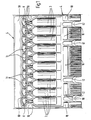
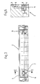
- a plastic tube is inserted between the two mutually movable halves of a molding tool, which consists of a left molding shell, a correspondingly shaped right molding shell, a left head cheek 2 adjoining the upper end of the left molding shell 1, and a right head cheek correspondingly designed for this purpose.
- a molding tool which consists of a left molding shell, a correspondingly shaped right molding shell, a left head cheek 2 adjoining the upper end of the left molding shell 1, and a right head cheek correspondingly designed for this purpose.
- the wall of the plastic tube lies against the recesses 5 provided for forming the ampoule bodies in the molded shells, since sterile air is introduced into each ampoule body by means of a blowing mandrel.
- the two halves forming them are welded together.
- the two molded shells and the two head cheeks are provided with depressions 6 of different shape and size in the area forming the waste edge zones 4.
- a depression 7 is also provided in the section lying between the neck part and its adjacent ampoules 3.
- Hollow bodies 10 are also formed with the aid of the depressions 6 and 7. This shaping and the subsequent welding of their two halves takes place simultaneously with the shaping of the ampoules 3 and the welding of their two halves.
- the hollow bodies 10 form a frame surrounding the ampoule block, which has a high stability thanks to the hollow bodies 10.
- the ampoules 3 are filled before they leave the molding tool and then closed with the aid of the head jaws, which can be displaced independently of the molding shells, while at the same time forming a toggle 11 which facilitates opening.
- the molded part formed from the ampoule block and the waste edge zone 4 surrounding it is removed from the tool, and thanks to the high stability of the waste edge zone 4 the removal is then also possible safely and without problems, if the ampoules 3 are not yet completely cooled and / or filled.
Landscapes
- Health & Medical Sciences (AREA)
- Mechanical Engineering (AREA)
- Engineering & Computer Science (AREA)
- Public Health (AREA)
- Animal Behavior & Ethology (AREA)
- General Health & Medical Sciences (AREA)
- Life Sciences & Earth Sciences (AREA)
- Veterinary Medicine (AREA)
- Pharmacology & Pharmacy (AREA)
- Manufacturing & Machinery (AREA)
- Hematology (AREA)
- Lining Or Joining Of Plastics Or The Like (AREA)
- Blow-Moulding Or Thermoforming Of Plastics Or The Like (AREA)
- Moulds For Moulding Plastics Or The Like (AREA)
Applications Claiming Priority (2)
| Application Number | Priority Date | Filing Date | Title |
|---|---|---|---|
| DE3831957A DE3831957C1 (fr) | 1988-09-21 | 1988-09-21 | |
| DE3831957 | 1988-09-21 |
Publications (3)
| Publication Number | Publication Date |
|---|---|
| EP0359971A2 true EP0359971A2 (fr) | 1990-03-28 |
| EP0359971A3 EP0359971A3 (en) | 1990-07-04 |
| EP0359971B1 EP0359971B1 (fr) | 1992-02-26 |
Family
ID=6363346
Family Applications (1)
| Application Number | Title | Priority Date | Filing Date |
|---|---|---|---|
| EP89114649A Expired - Lifetime EP0359971B1 (fr) | 1988-09-21 | 1989-08-08 | Procédé de fabrication de récipients creux en matière plastique |
Country Status (6)
| Country | Link |
|---|---|
| US (1) | US6426035B1 (fr) |
| EP (1) | EP0359971B1 (fr) |
| JP (1) | JPH0649326B2 (fr) |
| CA (1) | CA1330480C (fr) |
| DE (1) | DE3831957C1 (fr) |
| ES (1) | ES2030566T3 (fr) |
Cited By (3)
| Publication number | Priority date | Publication date | Assignee | Title |
|---|---|---|---|---|
| EP0539169A1 (fr) * | 1991-10-22 | 1993-04-28 | WEILER ENGINEERING Inc | Article avec forme permettant de déterminer sa position; procédé et appareil pour la production et le traitement de cet article |
| WO2009106219A1 (fr) | 2008-02-28 | 2009-09-03 | Bernd Hansen | Dispositif de séparation |
| US10821650B2 (en) | 2007-08-28 | 2020-11-03 | Bernd Hansen | Separating device |
Families Citing this family (15)
| Publication number | Priority date | Publication date | Assignee | Title |
|---|---|---|---|---|
| KR100567922B1 (ko) * | 1998-05-07 | 2006-07-06 | 정남승 | 절취되는 미세노즐이 마개와 일체로 형성토록 되는 주사약액용기의 제조방법및 금형 |
| KR100852634B1 (ko) * | 2002-07-08 | 2008-08-18 | 주식회사 중외 | 플라스틱 앰플의 제조장치 및 그 장치를 이용한 플라스틱앰플의 제조방법 |
| USD518891S1 (en) | 2002-11-20 | 2006-04-11 | Discount Rx, Inc. | Disposable vial |
| DE10328198A1 (de) | 2003-06-24 | 2005-01-20 | Bernd Hansen | Prägevorrichtung |
| USD556321S1 (en) * | 2005-11-22 | 2007-11-27 | Starnes Charles D | Medical vials |
| DE102006009766A1 (de) * | 2006-03-01 | 2007-09-06 | Bernd Hansen | Behälter sowie Vorrichtung zum Herstellen desselben |
| US7866514B1 (en) | 2006-03-01 | 2011-01-11 | Bernd Hansen | Container and device for production of such container |
| US7980405B2 (en) * | 2007-12-28 | 2011-07-19 | Hei Jun An | Individually detachable container pack |
| DE102010003350A1 (de) | 2010-03-26 | 2011-09-29 | Krones Ag | Verfahren zum Herstellen von Kunststoffbehältern |
| US20120186754A1 (en) * | 2011-01-20 | 2012-07-26 | Klem Christopher S | Sectional door panel and method of thermoforming |
| DE102011115256A1 (de) | 2011-09-27 | 2013-03-28 | Bernd Hansen | Verfahren zum Einbringen mindestens einer Struktur in ein Kunststoffbehältererzeugnis |
| US9346571B2 (en) | 2013-10-31 | 2016-05-24 | Pall Corporation | Multi-chamber freezing bag |
| DE102018000885A1 (de) | 2018-02-03 | 2019-08-08 | Kocher-Plastik Maschinenbau Gmbh | Vorrichtung |
| CN112959604B (zh) * | 2021-02-02 | 2022-09-30 | 西安双健包装有限公司 | 一种塑料杯成型机及其成型工艺 |
| DE102022003000A1 (de) | 2022-08-17 | 2024-02-22 | Kocher-Plastik Maschinenbau Gmbh | Vorrichtung |
Family Cites Families (19)
| Publication number | Priority date | Publication date | Assignee | Title |
|---|---|---|---|---|
| GB151397A (en) * | 1916-07-05 | 1920-09-30 | Fred Thomas Roberts | Improvements in and relating to a method of and apparatus for making hollow rubber articles |
| US1654647A (en) * | 1921-07-23 | 1928-01-03 | Penn Rubber Products Corp | Method of making hollow articles |
| US2991500A (en) * | 1954-06-14 | 1961-07-11 | Hagen Norbert | Method and apparatus for making plastic containers |
| NL196192A (fr) * | 1954-06-14 | |||
| NL111278C (fr) * | 1960-10-13 | |||
| DE1454947B1 (de) * | 1963-07-08 | 1971-03-11 | Battenfeld Geb | Verfahren und vorrichtung zum blasen von mit öffnung versehenen hohlkörpern |
| US3339232A (en) * | 1963-07-08 | 1967-09-05 | Battenfeld Werner | Apparatus for the production of hollow bodies in a blowing process |
| DE1272807B (de) * | 1963-10-30 | 1968-07-11 | Gerhard Hansen | Vorrichtung zum Herstellen, Fuellen und Verschliessen eines Behaelters aus thermoplastischem Kunststoff |
| US3325860A (en) * | 1963-10-30 | 1967-06-20 | Hansen Gerhard | Moulding and sealing machines |
| US3583036A (en) * | 1969-04-07 | 1971-06-08 | Koehring Co | Double web differential forming apparatus |
| US3597793A (en) * | 1969-05-28 | 1971-08-10 | Automatic Liquid Packaging | Bottles and the method and apparatus for forming them |
| GB1358957A (en) * | 1972-04-26 | 1974-07-03 | Lamp S Prospero Spa Lavorazion | Container for articles such as suppositories |
| GB1465564A (en) * | 1974-04-24 | 1977-02-23 | Du Pont | Laminated article |
| US3935358A (en) * | 1973-03-29 | 1976-01-27 | E. I. Du Pont De Nemours & Co. | Process for preparing a hollow, rib-reinforced laminated structure |
| GB1487440A (en) * | 1975-05-21 | 1977-09-28 | Ashford P | Production of hollow articles |
| DE2636262B2 (de) * | 1976-08-12 | 1978-11-30 | Agefko Kohlensaeure-Industrie Gmbh, 4000 Duesseldorf | Vorrichtung zum Blasen eines Hohlkörpers |
| US4423000A (en) * | 1980-10-17 | 1983-12-27 | Syoichi Teraoka | Method for molding hollow plastic articles |
| US4502616A (en) * | 1982-01-04 | 1985-03-05 | Health Care Concepts, Inc. | Single use vial |
| IT8253314V0 (it) * | 1983-11-04 | 1982-05-21 | Farmigea Spa | Minicontenitori monodose o plurido se di prodotti farmaceutici |
-
1988
- 1988-09-21 DE DE3831957A patent/DE3831957C1/de not_active Expired
-
1989
- 1989-08-08 ES ES198989114649T patent/ES2030566T3/es not_active Expired - Lifetime
- 1989-08-08 EP EP89114649A patent/EP0359971B1/fr not_active Expired - Lifetime
- 1989-09-18 CA CA000611775A patent/CA1330480C/fr not_active Expired - Lifetime
- 1989-09-20 JP JP1246241A patent/JPH0649326B2/ja not_active Expired - Fee Related
-
1991
- 1991-01-09 US US07/637,971 patent/US6426035B1/en not_active Expired - Lifetime
Cited By (6)
| Publication number | Priority date | Publication date | Assignee | Title |
|---|---|---|---|---|
| EP0539169A1 (fr) * | 1991-10-22 | 1993-04-28 | WEILER ENGINEERING Inc | Article avec forme permettant de déterminer sa position; procédé et appareil pour la production et le traitement de cet article |
| US5503885A (en) * | 1991-10-22 | 1996-04-02 | Weiler Engineering, Inc. | Article with position-defining structure and method and apparatus for making and processing same |
| US10821650B2 (en) | 2007-08-28 | 2020-11-03 | Bernd Hansen | Separating device |
| US11318657B2 (en) | 2007-08-28 | 2022-05-03 | Bernd Hansen | Method using separating system for containers |
| WO2009106219A1 (fr) | 2008-02-28 | 2009-09-03 | Bernd Hansen | Dispositif de séparation |
| DE102008011772A1 (de) | 2008-02-28 | 2009-09-03 | Bernd Hansen | Trennvorrichtung |
Also Published As
| Publication number | Publication date |
|---|---|
| JPH02113928A (ja) | 1990-04-26 |
| JPH0649326B2 (ja) | 1994-06-29 |
| DE3831957C1 (fr) | 1989-12-28 |
| ES2030566T3 (es) | 1992-11-01 |
| EP0359971B1 (fr) | 1992-02-26 |
| US6426035B1 (en) | 2002-07-30 |
| CA1330480C (fr) | 1994-07-05 |
| EP0359971A3 (en) | 1990-07-04 |
Similar Documents
| Publication | Publication Date | Title |
|---|---|---|
| EP0359971B1 (fr) | Procédé de fabrication de récipients creux en matière plastique | |
| DE2613689C2 (de) | Verfahren und Vorrichtung zum Herstellen eines Behälters aus thermoplastischem Kunststoff | |
| DE3439285C2 (de) | Verfahren zum Herstellen eines Hohlkörpers aus thermoplastischem Kunststoff und Vorrichtung zum Durchführen des Verfahrens | |
| DE2939761C2 (fr) | ||
| DE2307727B2 (de) | Verfahren und Vorrichtung zum Formen eines Hohlkörpers | |
| DE2703454C2 (de) | Verfahren zum Herstellen einer Flasche durch Blasformen | |
| DE4417979A1 (de) | Verfahren zum Herstellen mehrteiliger Spritzguß-Formteile und Werkzeug zur Durchführung des Verfahrens | |
| DE3429141C2 (de) | Verfahren zur Herstellung eines Hohlkörpers | |
| DE10030246C5 (de) | Werkzeug zum Mehrkomponentenspritzgießen von Kunststoff-Zahnbürstenkörpern für Zahnbürsten | |
| EP1053857B1 (fr) | Machine à souffler pour soufflage avec bavures réduites | |
| DE2400850A1 (de) | Verfahren und vorrichtung zum herstellen, fuellen und verschliessen von hohlkoerpern | |
| DE2709572A1 (de) | Vorrichtung zur kontinuierlichen herstellung orientierter hohlkoerper aus thermoplastischem material | |
| DE4236262A1 (de) | Spritzgußvorrichtung | |
| EP0626248B1 (fr) | Moule creux pour la fabrication de corps creuse avec poignées | |
| DE19809990C2 (de) | Verfahren und Vorrichtung zur Herstellung von Kunststoff-Hohlkörpern | |
| DE102005009276B4 (de) | Blasformsystem und Verfahren zur Herstellung von Hohlkörpern | |
| EP0087828A1 (fr) | Procédé pour la production de récipients en matière plastique | |
| DE2457758C3 (de) | Vorrichtung zum Herstellen, Füllen und Verschließen von Hohlkörpern aus thermoplastischem Material | |
| EP4392337B1 (fr) | Récipient en plastique moulé par étirage-soufflage et son procédé de production | |
| EP0714751A1 (fr) | Dispositif pour transporter une paraison d'une filière annulaire au moule de soufflage d'une machine de moulage par soufflage | |
| EP0734837A1 (fr) | Dispositif pour transporter une paraison d'une filière annulaire au moule de soufflage d'une machine de moulage par soufflage | |
| EP0887173A1 (fr) | Procédé et dispositif pour le moulage par soufflage de corps creux cintrés en matière thermoplastique | |
| DE2456723C2 (de) | Vorrichtung zum Herstellen eines einen Griff aufweisenden Behälters aus thermoplastischem Kunststoff | |
| EP4446087A1 (fr) | Moule d'injection, procédé de nettoyage pour un moule d'injection et procédé de moulage par injection | |
| DE2418638C3 (de) | Verfahren und Vorrichtung zum Her stellen von einseitig geschlossenen Hohlkörpern aus thermoplastischem Kunststoff |
Legal Events
| Date | Code | Title | Description |
|---|---|---|---|
| PUAI | Public reference made under article 153(3) epc to a published international application that has entered the european phase |
Free format text: ORIGINAL CODE: 0009012 |
|
| AK | Designated contracting states |
Kind code of ref document: A2 Designated state(s): ES FR GB IT SE |
|
| PUAL | Search report despatched |
Free format text: ORIGINAL CODE: 0009013 |
|
| AK | Designated contracting states |
Kind code of ref document: A3 Designated state(s): ES FR GB IT SE |
|
| 17P | Request for examination filed |
Effective date: 19900609 |
|
| 17Q | First examination report despatched |
Effective date: 19910507 |
|
| GRAA | (expected) grant |
Free format text: ORIGINAL CODE: 0009210 |
|
| AK | Designated contracting states |
Kind code of ref document: B1 Designated state(s): ES FR GB IT SE |
|
| ET | Fr: translation filed | ||
| ITF | It: translation for a ep patent filed | ||
| GBT | Gb: translation of ep patent filed (gb section 77(6)(a)/1977) | ||
| REG | Reference to a national code |
Ref country code: ES Ref legal event code: FG2A Ref document number: 2030566 Country of ref document: ES Kind code of ref document: T3 |
|
| PLBE | No opposition filed within time limit |
Free format text: ORIGINAL CODE: 0009261 |
|
| STAA | Information on the status of an ep patent application or granted ep patent |
Free format text: STATUS: NO OPPOSITION FILED WITHIN TIME LIMIT |
|
| 26N | No opposition filed | ||
| EAL | Se: european patent in force in sweden |
Ref document number: 89114649.0 |
|
| REG | Reference to a national code |
Ref country code: GB Ref legal event code: IF02 |
|
| PGFP | Annual fee paid to national office [announced via postgrant information from national office to epo] |
Ref country code: ES Payment date: 20080714 Year of fee payment: 20 |
|
| PGFP | Annual fee paid to national office [announced via postgrant information from national office to epo] |
Ref country code: FR Payment date: 20080805 Year of fee payment: 20 Ref country code: IT Payment date: 20080826 Year of fee payment: 20 |
|
| PGFP | Annual fee paid to national office [announced via postgrant information from national office to epo] |
Ref country code: GB Payment date: 20080702 Year of fee payment: 20 |
|
| PGFP | Annual fee paid to national office [announced via postgrant information from national office to epo] |
Ref country code: SE Payment date: 20080807 Year of fee payment: 20 |
|
| EUG | Se: european patent has lapsed | ||
| REG | Reference to a national code |
Ref country code: ES Ref legal event code: FD2A Effective date: 20090810 |
|
| PG25 | Lapsed in a contracting state [announced via postgrant information from national office to epo] |
Ref country code: GB Free format text: LAPSE BECAUSE OF EXPIRATION OF PROTECTION Effective date: 20090807 |
|
| PG25 | Lapsed in a contracting state [announced via postgrant information from national office to epo] |
Ref country code: ES Free format text: LAPSE BECAUSE OF EXPIRATION OF PROTECTION Effective date: 20090810 |